Bulletin PD-20723 rev. B 07/01
409CNQ... SERIES
SCHOTTKY RECTIFIER 400 Amp
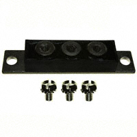
TO-244AB
Major Ratings and Characteristics Characteristics
IF(AV) Rectangular waveform VRRM range IFSM @ tp = 5 µs sine VF TJ @ 200Apk, TJ=125°C range
Description/Features
The 409CNQ center tap Schottky rectifier module series has been optimized for low reverse leakage at high temperature. The proprietary barrier technology allows for reliable operation up to 175 °C junction temperature. Typical applications are in high current switching power supplies, plating power supplies, UPS systems, converters, free-wheeling diodes, welding, and reverse battery protection. 175 °C TJ operation Center tap module High purity, high temperature epoxy encapsulation for enhanced mechanical strength and moisture resistance Low forward voltage drop High frequency operation Guard ring for enhanced ruggedness and long term reliability
409CNQ... Units
400 135 to 150 20000 0.72 A V A V
(per leg)
- 55 to 175
°C
80.01 [3.150] 40.26 [1.585] 39.75 [1.565] COMMON CATHODE
Ø
10.41 [.410] 9.65 [.380]
20.32 [.800] 17.78 [.700]
LUG TERMINAL ANODE 1
LUG TERMINAL ANODE 2
2X Ø
7.49 [.295] 6.99 [.275]
34.925 [1.375] REF. 63.50 [2.500] 60.96 [2.400]
Ø
4.95 [.195] 4.70 [.185]
1/4-20 SLOTTED HEX
BASE COMMON CATHODE
23.55 [.927] 20.42 [.804]
15.75 [.620] 14.99 [.590] 3.35 [.132] 3.02 [.119]
92.71 [3.650] 90.17 [3.550] NOTES: 1. DIMENSIONS ARE SHOWN IN MILLIMETERS [INCHES]. 2. CONTROLLING DIMENSION: MILLIMETER
Modified JEDEC Outline TO-244AB Dimensions in millimeters and (inches)
www.irf.com
1
�409CNQ... Series
Bulletin PD-20723 rev. B 07/01
Voltage Ratings
Part number
VR Max. DC Reverse Voltage (V) VRWM Max. Working Peak Reverse Voltage (V)
409CNQ135
135
409CNQ150
150
Absolute Maximum Ratings
Parameters
IF(AV) Max. Average Forward Current (Per leg) * See Fig. 5 (Per device ) IFSM Max. Peak One Cycle Non-Repetitive Surge Current (Per Leg) * See Fig. 7 EAS Non-Repetitive Avalanche Energy (Per Leg) IAR Repetitive Avalanche Current (Per Leg)
409CNQ Units Conditions
200 400 20000 2300 15 1 A mJ A Following any rated load condition and with 10ms Sine or 6ms Rect. pulse rated VRRM applied 5µs Sine or 3µs Rect. pulse TJ = 25 °C, IAS = 1 Amps, L = 30 mH Current decaying linearly to zero in 1 µsec Frequency limited by TJ max. VA = 1.5 x VR typical A 50% duty cycle @ TC = 125 °C, rectangular wave form
Electrical Specifications
Parameters
VFM Max. Forward Voltage Drop (Per Leg) * See Fig. 1 (1)
409CNQ Units
1.03 1.21 0.72 0.83 6 85 6000 5.0 10000 V V V V mA mA pF nH V/ µs @ 200A @ 400A @ 200A @ 400A TJ = 25 °C TJ = 125 °C
Conditions
TJ = 25 °C TJ = 125 °C VR = rated VR
IRM CT LS
Max. Reverse Leakage Current (Per Leg) * See Fig. 2 Typical Series Inductance (1) (Per Leg) Max. Junction Capacitance (Per Leg)
VR = 5VDC, (test signal range 100Khz to 1Mhz) 25°C From top of terminal hole to mounting plane
dv/dt Max. Voltage Rate of Change (Rated VR)
Thermal-Mechanical Specifications
Parameters
TJ Tstg Max. Junction Temperature Range Max. Storage Temperature Range
(1) Pulse Width < 300µs, Duty Cycle
很抱歉,暂时无法提供与“409CNQ135”相匹配的价格&库存,您可以联系我们找货
免费人工找货