Bulletin I2107 rev. F 03/03
SAFEIR Series 40TPS..
PHASE CONTROL SCR VT
< 1.45V @ 40A
ITSM = 500A VRRM = 800 - 1200V
Description/ Features
The 40TPS... SAFEIR series of silicon controlled rectifiers are specifically designed for medium power switching and phase control applications. The glass passivation technology used has reliable operation up to 125°C junction temperature. Low Igt parts available. Typical applications are in input rectification (soft start) and these products are designed to be used with International Rectifier input diodes, switches and output rectifiers which are available in identical package outlines.
Major Ratings and Characteristics Characteristics
IT(AV) Sinusoidal waveform IRMS VRRM/ VDRM Range ITSM VT dv/dt di/dt TJ @ 40 A, TJ = 25°C 55 800 - 1200 500 1.45 1000 100 - 40 to 125 A V A V V/µs A/µs °C
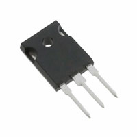
Package Outline Units
A
40TPS..
35
TO-247AC
www.irf.com
1
�40TPS.. SAFEIR Series
Bulletin I2107 rev. F 03/03
Voltage Ratings
VRRM/ VDRM, max. repetitive Part Number
40TPS08 40TPS12
VRSM , maximum non repetitive peak reverse voltage V
900 1300
IRRM/ IDRM 125°C mA
10
peak and off-state voltage V
800 1200
Absolute Maximum Ratings
Parameters
IT(AV) Max. Average On-state Current IT(RMS) Max. Continuous RMS On-state Current As AC switch ITSM I2t Max. Peak One Cycle Non-Repetitive Surge Current Max. I 2t for Fusing 500 600 1250 1760 I √t
2
40TPS..
35 55
Units
A
Conditions
@ TC = 79° C, 180° conduction half sine wave
A
10ms Sine pulse, rated VRRM applied 10ms Sine pulse, no voltage reapplied
Initial TJ = TJ max.
A2s
10ms Sine pulse, rated VRRM applied 10ms Sine pulse, no voltage reapplied
Max. I √t for Fusing
2
12500 1.02
A √s V
2
t = 0.1 to 10ms, no voltage reapplied TJ = 125°C
VT(TO)1 Low Level Value of Threshold Voltage VT(TO)2 High Level Value of Threshold Voltage rt1 rt2 VTM di/dt IH IL IRRM/ IDRM dv/dt Low Level Value of On-state Slope Resistance High Level Value of On-state Slope Resistance Max. Peak On-state Voltage Max. Rate of Rise of Turned-on Current Max. Holding Current Max. Latching Current Max. Reverse and Direct Leakage Current Max. Rate of Rise of Off-state Voltage 40TPS08 40TPS12
1.23
9.74
mΩ
7.50
1.85 100 150 300 0.5 10 500 1000
V A/µs mA
@ 110A, TJ = 25°C TJ = 25°C
mA
TJ = 25°C TJ = 125°C
VR = rated VRRM/ VDRM
V/µs
TJ = TJ max., linear to 80% VDRM , Rg-k = open
2
www.irf.com
�40TPS.. SAFEIR Series
Bulletin I2107 rev. F 03/03
Triggering
Parameters
PGM Max. peak Gate Power PG(AV) Max. average Gate Power IGM Max. peak Gate Current
40TPS..
10 2.5 2.5 10 4.0 2.5 1.7
Units
W
Conditions
A V TJ = - 40°C TJ = 25°C TJ = 125°C mA TJ = - 40°C TJ = 25°C TJ = 125°C TJ = 25°C, for 40TPS08A V mA TJ = 125°C, V DRM = rated value Anode supply = 6V resistive load
- V GM Max. peak negative Gate Voltage VGT Max. required DC Gate Voltage to trigger
IGT
Max. required DC Gate Current to trigger
270 150 80 40
V GD IGD
Max. DC Gate Voltage not to trigger Max. DC Gate Current not to trigger
0.25 6
Thermal-Mechanical Specifications
Parameters
TJ Tstg Max. Junction Temperature Range Max. Storage Temperature Range
40TPS..
- 40 to 125 - 40 to 125 0.6
Units
°C
Conditions
RthJC Max. Thermal Resistance Junction to Case RthJA Max. Thermal Resistance Junction to Ambient RthCS Max. Thermal Resistance Case to Heatsink wt T Approximate Weight Mounting Torque Min. Max. Case Style
°C/W
DC operation
40
0.2
Mounting surface, smooth and greased
6 (0.21) 6 (5) 12 (10)
g (oz.) Kg-cm (lbf-in)
TO-247AC
www.irf.com
3
�40TPS.. SAFEIR Series
Bulletin I2107 rev. F 03/03
Maximum Allowable Case Temperature (°C)
Maximum Allowable Case T emperature (°C)
130 120 110
40T .. S PS eries R thJC (DC) = 0.6 °C/ W
130 120 110
40T .. S PS eries RthJC (DC) = 0.6 °C/ W
Conduction Angle
Conduction Period
100 90 80 70
30°
100 90 80 70 0 10 20 30 40 50 60 Average On-state Current (A) 30° 60°
60° 90° 120° 180°
90° 120° 180° DC
0
10
20
30
40
Average On-state Current (A)
Fig. 1 - Current Rating Characteristics
Maximum Avera g e On-state Power Loss (W)
Fig. 2 - Current Rating Characteristics
Maximum Averag e On-state Power Loss (W) 80 70 60 50 DC 180° 120° 90° 60° 30°
60 50 40 30 20 10 0 0 5 10 15 20 25 30 35 40 Avera ge On-sta te Current (A) 180° 120° 90° 60° 30°
RMS Limit
40 RMSLimit 30 20 10 0 40T .. S PS eries TJ = 125°C 0 10 20 30 40 50 60
Conduction Angle
Conduction Period
40T .. S PS eries TJ= 125°C
Avera ge On-sta te Current (A)
Fig. 3 - On-state Power Loss Characteristics
550 500 450 400 350 300 250
Fig. 4 - On-state Power Loss Characteristics
600 550 500 450 400 350 300 40T .. S PS eries
Peak Half S Wave On-state Current (A) ine
40T .. S PS eries 1 10 100
Peak Half S Wa ve On-state Current (A) ine
At Any R ted Load Condition And With a Rated V RRM Ap plied F ollowing Surge. Initia l TJ= 125°C @60 Hz 0.0083 s @50 Hz 0.0100 s
Ma ximum Non Rep etitive S urge Current Versus Pulse T rain Duration. Control Of Conduction May Not Be Maintained. Initial TJ = 125°C No Voltage R eap p lied Rated V eap p lied RRM R
250 0.01
0.1 Pulse T in Duration (s) ra
1
Number Of Equal Amplitude Half Cycle Current Puls (N) es
Fig. 5 - Maximum Non-Repetitive Surge Current
Fig. 6 - Maximum Non-Repetitive Surge Current
4
www.irf.com
�40TPS.. SAFEIR Series
Bulletin I2107 rev. F 03/03
100 Instanta neous On-s te Current (A) ta
10
TJ= 25°C TJ= 125°C
40T .. S PS eries 1 0.5
1
1.5
2
Instantaneous On-state Voltag e (V)
Fig. 7 - On-state Voltage Drop Characteristics
100 Instantaneous Gate Voltage (V)
10
Rec tangular gate pulse a)Rec ommended load line for rated di/ dt: 20 V, 30 ohms tr = 0.5 µs, tp >= 6 µs b)R ommended load line for ec = 6 µs
(1) PGM = 100 W, tp = 500 µs (2) PGM = 50 W, tp = 1 ms (3) PGM = 20 W, tp = 25 ms (4) PGM = 10 W, tp = 5 ms
(a)
(b)
T = -40 °C J T = 25 °C J T = 125 °C J
1 VGD IGD 0.1 0.001 0.01
(4) (3)
(2) (1)
40T .. PS 0.1 1
Frequenc y Limited by PG(AV) 10 100 1000
Instantaneous Gate Current (A)
Fig. 8 - GateCharacteristics
T ransient T hermal Impeda nc e Z thJC (°C/W) 1
0.1
D = 0.50 D = 0.33 D = 0.25 D = 0.17 D = 0.08
S teady S tate Value (DC Opera tion)
S ingle Pulse 40T .. S PS eries 0.01 0.0001
0.001
0.01 S quare Wave Pulse Duration (s)
0.1
1
Fig. 9 - Thermal Impedance ZthJC Characteristics
www.irf.com
5
�40TPS.. SAFEIR Series
Bulletin I2107 rev. F 03/03
Outline Table
15 .90 (0 .626 ) 15 .30 (0 .602 ) 5. 70 (0 .22 5) 5.30 ( 0.208) 20 .30 (0 .800 ) 19 .70 (0 .775 ) 5.50 ( 0.217) 4. 50 (0 .17 7) 1 2 3 ( 2 PLCS.) 3. 65 ( 0 .14 4) 3. 55 ( 0 .13 9)
DIA.
5. 30 ( 0 .20 9) 4.70 ( 0.185) 2.5 ( 0.098)
1.5 ( 0.059)
14. 80 ( 0.583)
14 .20 (0 .559 )
4. 30 ( 0 .17 0) 3. 70 ( 0 .14 5)
1. 40 ( 0 .05 6)
2. 20 (0 .08 7) M AX. 0.80 ( 0.032) 0. 40 ( 0 .21 3)
2. 40 (0 .09 5) M AX.
1. 00 ( 0 .03 9) 10. 94 ( 0.430) 10 .86 ( 0 .427 )
Dimensions in millimeters and inches
Marking Information
EXAMPLE: THIS IS A 40TPS12 WITH ASSEMBLY LOT CODE 5657 ASSEMBLED ON WW 35, 2000 IN THE ASSEMBLY LINE "H"
INTERNATIONAL RECTIFIER LOGO ASSEMBLY LOT CODE
PART NUMBER 40TPS12
035H 56 57
DATE CODE YEAR 0 = 2000 WEEK 35 LINE H
6
www.irf.com
�40TPS.. SAFEIR Series
Bulletin I2107 rev. F 03/03
Ordering Information Table
Device Code
40
1
T
2
P
3
S
4
12
5 6
2 (A)
1 2 3 4 5 6
-
Current Rating Circuit Configuration: T = Thyristor Package: T = TO-247 Type of Silicon: S = Standard Recovery Rectifier Voltage code: Code x 100 = VRRM None = Standard Igt selection A = Low Igt selection 40mA max. only for 40TPS08A 08 = 800V 12 = 1200V
1 (K) (G) 3
Data and specifications subject to change without notice. This product has been designed and qualified for Industrial Level. Qualification Standards can be found on IR's Web site.
IR WORLD HEADQUARTERS: 2 33 Kansas St., El Segundo, California 90245, USA Tel: (310) 252-7105 TAC Fax: (310) 252-7309 Visit us at www.irf.com for sales contact information. 03/03
www.irf.com
7
�
很抱歉,暂时无法提供与“40TPS08A”相匹配的价格&库存,您可以联系我们找货
免费人工找货