IRPLDIM4E
Miniature Dimmable 26W Ballast Using IRS2530D DIM8TM Control IC
Table of Contents
Page 1. Overview ..........................................................................................2 2. Features ...........................................................................................2 3. Electrical Characteristics ..................................................................3 4. Fault Protection Characteristics .......................................................3 5. IRS2530D DIM8TM Ballast Control IC...............................................4 6. Circuit Description ............................................................................4 7. Circuit Schematics ...........................................................................5 8. Bill of Materials.................................................................................6 9. Functional Description......................................................................7 10. Fault Conditions ...........................................................................10 11. PCB Layout and Component Placement......................................14 12. Inductor Specifications .................................................................17
www.irf.com
RD0801
-1-
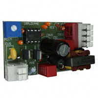
�1. Overview
The IRPLDIM4E Reference Design is a miniature dimmable electronic ballast for driving 26W compact fluorescent lamps from a 220VAC line. The circuit provides all of the necessary functions for preheat, ignition, and dimming control of the lamp and also includes the EMI filter and AC rectification stage. The ballast size is 1.42in x 2.44in (36mm x 62mm). The circuit is designed around the IRS2530D(S)PbF DIM8TM Ballast Control IC. The IRS2530D includes adjustable preheat time, frequency sweeping for filament preheating and lamp ignition, a dimming reference and feedback input, a high soft-start frequency to avoid lamp flash, lamp and ballast fault protection for open filament condition, failure to strike, and no lamp fault conditions, automatic restart during lamp exchange, and, low AC line protection. The IRS2530D is simple to use, has only 8 pins, and drastically reduces component count for a complete dimming solution.
2. Features
Closed-loop dimming control Programmable preheat time Frequency sweep for filament preheat and lamp ignition Open filaments and no-lamp protection Failure to strike and deactivated-lamp protection Low AC line protection Lamp exchange auto restart
www.irf.com
RD0801
-2-
�3. Electrical Characteristics
Parameter Lamp Type Input Power Input Current Lamp Running Voltage Lamp Running Current Start Frequency Run Frequency Preheat Time Input AC Voltage Range Ballast turn-off voltage † Units [W] [mArms] [Vpp] [mArms] [kHz] [kHz] [s] [VACrms] [VACrms]
TABLE 3.1: Ballast Parameters.
Dimming Level 100% 10% 100% 10% 100% 10% 100% 10% 100% 10%
Value 26W CFL 25 9 180 78 320† 480 271 26 115 42 68 1 200 - 250 85
The lamp running voltage at 100% dimming level is not perfectly sinusoidal and has some distortion.
4. Fault Protection Characteristics
Fault Brown-out Upper filament broken Lower filament broken Lamp removed Failure to ignite No lamp End of life Protection Non-ZVS Crest Factor Over Current Crest Factor Over Current Crest Factor Over Current VVCOFLT+ VLOSDCrest Factor Over Current Ballast Increase frequency Deactivates Deactivates Deactivates Deactivates Does not start Deactivates Restart Operation Line voltage increase Lamp exchange Lamp exchange Lamp inserted Lamp exchange Lamp inserted Lamp exchange
TABLE 4.1: Fault Protections Characteristics.
www.irf.com
RD0801
-3-
�5. IRS2530D DIM8TM Ballast Control IC
The IRS2530D is an application specific solution for dimming CFL and TL lamps in CFL or matchbox (small size ballasts) applications. It integrates all of the necessary functions for preheat, ignition and dimming control of the lamp, plus lamp fault protection, low AC-line protection, lamp exchange auto-restart, and a 600V half-bridge driver into a standard SO8 or DIP8 package. The IRS2530D includes adaptive zero-voltage switching, non-zero voltage switching (ZVS) protection, as well as an integrated 600V bootstrap MOSFET. The heart of this IC is a voltage-controlled oscillator (VCO) with a dimming reference/feedback input. One of the biggest advantages of the IRS2530D is that it uses the VS pin (the mid-point of the halfbridge) for over-current protection and to detect non-ZVS conditions. The IRS2530D uses the RDSon of the low-side half-bridge MOSFET for current sensing each cycle when the low-side MOSFET is on. An internal 600V MOSFET connects the VS pin to the VSsensing circuitry and allows for the VS pin to be accurately measured during the time when pin LO is high, while withstanding the high DC bus voltage during the other portion of the switching cycle when the high-side MOSFET is turned on. This eliminates the need for an external, precision current sensing resistor that is typically used to detect overcurrent. Please refer to the IRS2530D datasheet for further information including electrical parameters, a state diagram and a complete functional description. As a result of the IRS2530D features, the IRPLDIM4E Reference Design is a complete dimming ballast solution that includes lamp fault protection, low AC line protection, lamp exchange auto-restart, and reduces component count and ballast size.
6. Circuit Description
The schematic for IRPLDIM4E is shown in Figure 7.1. The bill of materials with the component values is shown in Table 8.1. The ballast incorporates a fuse, input rectifier, EMI filter, bus capacitor, half-bridge, dimming control and output stage. The output stage is a series-L, parallel-RC resonant circuit consisting of an inductor (LRES), capacitor (CRES), and lamp. The AC line input voltage is rectified to provide a bus voltage of approximately 300VDC. The start-up resistors, RVCC1 and RVCC2, are sized such that they supply the micro-power current during under-voltage lockout (UVLO) mode and determine the AC line voltage where the ballast turns-on. When VCC exceeds the startup threshold (VCCUV+), the IRS2530D begins to oscillate and the charge pump circuit (CVS, DCP1 and DCP2) supplies the current to VCC while maintaining the internal VCC zener clamp at 15.6V. The IRS2530D controls the frequency of the half-bridge for satisfying the lamp operating modes. These include lamp preheat, lamp ignition, dimming, low AC line protection and lamp/ballast fault protection.
www.irf.com
RD0801
-4-
�L 220V AC Line Input
LF BR1
F1
RVCC1
RVCC2
IC1 VCC CF CBUS CVCC COM VB
HO
MHS
2
CDIM DIM
7
VS CBS
LRES:A
CDC
3
CVCO VCO
6
LO RLO
CVS CRES
LRES:B
CFL LAMP 4 5
CFB CPH RVCO RFB MLS DCP2 RLMP2 RLMP1
CH1
RMAX
7. Circuit Schematic
Potentiometer Dimming PDIM Input
RMIN
CH2 DCP1
LRES:C
RCS
www.irf.com
RD0801
1
8
RHO
Figure 7.1: IRPLDIM4E Circuit Schematic
N
-5-
IRS2530D
�8. Bill of Materials
Item # 1 2 3 4 5 6 7 8 9 10 11 12 13 14 15 16 17 18 19 20 21 22 23 24 25 26 27 28 29 30 31 32 Total Qty 1 1 1 2 1 2 2 1 1 1 1 1 1 1 1 2 2 1 1 1 1 1 1 1 2 1 1 1 1 1 1 1 38 WAGO WAGO IR 235-202 235-204 IRPLDIM4E Manufacturer Digikey Diodes, Inc. Digikey Vishay Digikey Epcos Wima Digikey Panasonic Digikey Panasonic Digikey Panasonic Digikey Yageo Digikey Panasonic Digikey Panasonic Digikey Yageo Digikey Panasonic Wima TAW IR Vogt Digikey/Vishay Digikey Panasonic Digikey Panasonic Digikey Panasonic Digikey Panasonic Digikey Panasonic Digikey Panasonic Digikey Panasonic Digikey Yageo Digikey Panasonic Digikey Bourns Digikey Diodes, Inc. Digikey Diodes, Inc. Part Number RH06DICT-ND RHO6-T PPC.47BCT-ND
NFR25H0004707JR500
Description Bridge Rectifier, 600V, 0.5A MiniDip Resistor, 0.47R, 1/2W RF Chokes 1mH 200mA Capacitor, 47nF, 400V Capacitor, 10 F, 350VDC, 105C Capacitor, 0.1 F, 50V, 1206 Capacitor, 0.18 F, 25V, 1206 Capacitor, 2.2nF, 50V, 1206 Capacitor, 0.68 F, 25V, 1206 Capacitor, 1 F, 16V, 1206 Capacitor, 10nF, 50V, 1206 Capacitor, 1nF, 1KV, Ceramic disk Polypropylene Capacitor, 4.7nF/1.6KV, 10%, RM=15mm Dimming Ballast Control IC Ballast Resonant Inductor EF20, 2.3mH Transistor, MOSFET, 400V Resistor, 360K, 1206 Resistor, 7.5 Ohm, 5%, 1 W, Axial Resistor, 220K, 1206 Resistor, 470K, 1206 Resistor, 430 Ohm, 1%, 1206 Resistor, 200K, 1%, 1206 Resistor, 1K, 1206 Resistor, 1.5K, 1206 Resistor, 10 Ohm, 1206 Pot, 10K, Single turn Diode, 1N4148 SMT DL35 Zener Diode, 18V, 500mV, SMT Wire Jumper Connector, 2 terminal Connector, 4 terminal PCB, Single Layer BR1 F1 LF
Reference
M8301-ND 5800-102-RC MKS2 Series P5931-ND EEU-EB2V100 PCC104BCT-ND ECJ-3VB1H104K PCC1886CT-ND ECJ-3VB1E184K 311-1171-1-ND CC1206KRX7R9BB222 PCC1892CT-ND ECJ-3YBIE684K PCC1882CT-ND ECJ-3YB1C105K 311-1174-1-ND CC1206KRX7R9BB103 P9542-ND ECK-A3A102KBP MKP-10 RM15MM MKP 472K1K6 IRS2530D IR IL 070 503 11 02 IRFU320 P360KECT-ND ERJ-8GEYJ364V PPC7.5W-1CT-ND 5073NW7R500J12AFX P220KECT-ND ERJ-8GEYJ224V P470KECT-ND ERY-8GEYJ474V RHM430FCT-ND MCR18EZHF4300 P200KFCT-ND ERJ-8ENF2003V P1.0KALCT-ND ERJ-P08J102V 311-1.5KERCT-ND RC1206JR-071K5L P10ECT-ND ERJ-8GEYJ100V 3386P-103LF-ND 3386P-1-103LF LL4148DICT-ND ZMM5248BDICT-ND ZMM2548B-7
CF, CDC CBUS CBS, CFB CH1, CH2 CVCO CPH CVCC CDIM CVS CRES IC1 LRES MHS, MLS RVCC1, RVCC2 RCS RLMP1 RLMP2 RMIN RMAX RFB RVCO RHO, RLO PDIM DCP2 DCP1 J1 X1 X2
TABLE 8.1: IRPLDIM4E Bill of Materials. Lamp type: Spiral CFL 26W, Line Input Voltage: 200 - 250 VAC. Note: Different lamp types may require components with different values, voltage ratings and/or current ratings.
www.irf.com
RD0801
-6-
�9. Functional Description
When power is turned on, the IRS2530D first starts in Under Voltage Lockout (UVLO) mode. The UVLO mode is designed to maintain an ultra-low (5.5) during the on-time of LO, the IRS2530D will enter Fault Mode, where the half-bridge is off. Performing crest factor measurement provides a relative current measurement that cancels temperature and/or tolerance variations of the RDSon of the low-side half-bridge MOSFET. Figure 10.3 shows the voltage across the lamp and the VS voltage when the lower filament of the lamp is removed. Figure 10.4 shows these voltages when the upper filament of the lamp is removed. In both cases, the IRS2530D will enter the Fault Mode and shut down after detecting that the crest factor exceeds 5 during the on-time of LO. Figure 10.5 shows the VS pin, inductor current, and voltage across lamp when the inductor saturates and the ballast shuts down.
www.irf.com
RD0801
- 11 -
�Figure 10.3: Lower filament removed: CH2 is the VS voltage, CH4 is the voltage across the lamp
Figure 10.4: Upper filament removed: CH2 is the VS voltage, CH4 is the voltage across the lamp
www.irf.com
RD0801
- 12 -
�Figure 10.5: Inductor saturation: CH1 is the LO voltage, CH2 is the VS voltage, CH3 is the current through the resonant inductor, and CH4 is the voltage across the lamp
Figure 10.6 shows the VS voltage and the voltage across the lamp when the IC undergoes reset with a lamp exchange. When the lamp is removed, crest factor protection is triggered, and the IC enters the Fault mode and shuts down. Since the lamp is removed, LO pins is pulled above VLOSD+, and the IC goes to UVLO mode. When the lamp is re-inserted, the IC goes back to the Preheat / Ignition mode, and the halfbridge starts to oscillate again.
Figure 10.6: Lamp exchange: CH1 is the LO voltage, CH2 is the VS voltage, and CH4 is the voltage across the lamp
www.irf.com
RD0801
- 13 -
�11. PCB Layout and Component Placement
www.irf.com
RD0801
- 14 -
�www.irf.com
RD0801
- 15 -
�www.irf.com
RD0801
- 16 -
�12. Inductor Specifications
Vogt # IL 070 503 11 02 BI Technologies # HM00-07544
INDUCTOR SPECIFICATION
CORE SIZE GAP LENGTH
E20/10/ 6 (EF20) 1.0 mm
CORE MATERIAL Philips3C85 , Siemens N27 or equivalent NOMINAL INDUCTANCE TEST TEMPERATURE 2.3 100 mH C
WINDING START PIN FINISH PIN TURNS WIRE DIAMETER ( mm) MAIN CATHODE CATHODE 1 2 3 6 5 4 240* 5.5 5.5 10/ 38 Multistranded 26 awg insulated 26 awg insulated
PHYSICAL LAYOUT
( Vertical6- Pin Bobbin )
0.4" 6
Pin View
1 2 3 0.4"
5 4
TEST
TEST TEMPERATURE
100
MIN 2.1
C mH
MAX 2.4
MAIN WINDING INDUCTANCE *
Adjust turns for specified Inductance
mH
www.irf.com
RD0801
- 17 -
�