物料型号:
- 型号为IRS21091(S)PbF,其中“S”表示SOIC封装,“PbF”表示铅框架PDIP封装。
器件简介:
- IRS21091是一款高电压、高速的功率MOSFET和IGBT驱动器,具有依赖的高侧和低侧参考输出通道。专有的HVIC和锁存免疫CMOS技术实现了坚固的单片结构。逻辑输入兼容标准CMOS或LSTTL输出,低至3.3V逻辑。输出驱动器具有高脉冲电流缓冲级,旨在最小化驱动交叉导通。
引脚分配:
- 1号引脚:Vcc(供电电压)
- 2号引脚:IN(逻辑输入,与HO同相)
- 3号引脚:DT/SD(可编程死区时间引脚,连接到Vcc时禁用输入/输出逻辑)
- 4号引脚:COM(低侧返回)
- 5号引脚:LO(低侧栅驱动输出)
- 6号引脚:Vs(高侧浮动供电返回)
- 7号引脚:HO(高侧栅驱动输出)
- 8号引脚:VB(高侧浮动供电)
参数特性:
- 浮动通道设计用于自举操作。
- 完全操作至+600V。
- 容忍负瞬态电压,dV/dt免疫。
- 栅驱动电压范围从10V至20V。
- 两个通道均具有欠压锁定。
- 3.3V、5V和15V输入逻辑兼容。
- 交叉导电预防逻辑。
- 匹配的传播延迟,用于两个通道。
- 高侧输出与IN输入同相。
- 逻辑和电源地±5V偏移。
- 内部500ns死区时间,并且可以通过一个外部RDT电阻编程至5µs。
- 较低di/dt栅驱动,以获得更好的噪声免疫。
功能详解:
- IRS21091的浮动通道可用于驱动N沟道功率MOSFET或IGBT,适用于高侧配置,可操作高达600V。
应用信息:
- 该驱动器适用于需要高侧驱动的应用,如开关电源、电机控制等。
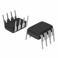
封装信息:
- 提供8引脚SOIC和8引脚PDIP封装。
- 8引脚PDIP封装的尺寸为0.3英寸间距,8引脚SOIC封装的尺寸为0.155英寸间距。
- 两种封装均符合环保要求,无铅。