Cover headline
Cover headline
MKJ5 Series Connectors
Miniature Circular Catalog
�Amazing things happen
when great things connect
ITT Cannon is a leading global manufacturer of connector products serving international customers in the aerospace and
defense, medical, energy, transportation and industrial end markets. Whether delivering critical specs to aircraft pilots,
streaming data through communications satellites or enabling ultrasound technology that gives an expectant mother the
first glimpse of her unborn child, Cannon connects the world’s most important information with the people who need it.
No one is more qualified to help meet mission-critical requirements and equip military personnel than ITT Cannon. With 100
years of interconnect excellence and seven decades of global presence in the Defense Industry, we are a committed partner
among today’s military equipment manufacturers. We continue to lead the market in interconnect solutions that support
combat preparation and to meet the military’s needs for adaptability, mobility and survivability. And we do so with one goal
in mind: to get our soldiers back home safely.
About ITT
ITT is a diversified leading manufacturer of highly
engineered critical components and customized
technology solutions for the energy, transportation and
industrial markets. Building on its heritage of innovation,
ITT partners with its customers to deliver enduring
solutions to the key industries that underpin our modern
way of life. This work is made possible by the talent and
innovation of committed ITT employees in more than 35
countries who create trusted products and brands such as
Goulds Pumps, KONI shock absorbers, Cannon connectors
and Enidine energy absorption devices. Founded in 1920,
ITT is headquartered in White Plains, N.Y. For more
information, visit itt.com
A Century of Connections
In 2015, Cannon marked its 100th Anniversary of
Innovation. Cannon products were used in the first
“talking” movies and helped transmit the first
messages back to earth when we landed on the
moon. Today we proudly continue our legacy of
innovating to connect the world and inspire the
successes of the next century – because amazing
things happen when great things connect.
Visit ittcannon.com to learn more.
Dimensions shown in inches (mm)
Specifications and dimensions subject to change
2
www.ittcannon.com
�Our connector portfolio remains one of the most extensive in the industry, providing
customers with a reliable and cost-effective range of interconnect solutions.
Visit ittcannon.com to learn more.
Medical Equipment
Marine Vessels
Rail
Soldier-Worn Systems
Unmanned Systems
Heavy Equipment
Commercial Aircraft
Oil & Gas
Dimensions shown in inches (mm)
Specifications and dimensions subject to change
www.ittcannon.com
3
�Table of Contents
MKJ Miniature Circular Connectors . . . . . . . . . . . . . . . . . . . . . . . . . . . . . . . . . . . . . . . 5
Coupling Styles . . . . . . . . . . . . . . . . . . . . . . . . . . . . . . . . . . . . . . . . . . . . . . . . . 6
Markets & Applications. . . . . . . . . . . . . . . . . . . . . . . . . . . . . . . . . . . . . . . . . . . . . 7
We Connect Aerospace & Defense Industry with Mission Critical Data & Signal Transmission . . . . . . . . 8
Product Overview - MKJ5 Triple Start. . . . . . . . . . . . . . . . . . . . . . . . . . . . . . . . . . . . . 9
MKJ5 Contact Arrangements & Layouts. . . . . . . . . . . . . . . . . . . . . . . . . . . . . . . . . . 10-11
MKJ5 Plug (Banded & Accessory Thread). . . . . . . . . . . . . . . . . . . . . . . . . . . . . . . . . 12-14
MKJ5 Receptacle In-Line, Box Mount/Square Flange, Jam Nut Rear Panel Mount . . . . . . . . . . . . 15-16
MKJ5 Receptacle In-Line (Banded & Accessory Thread) . . . . . . . . . . . . . . . . . . . . . . . . . . . 17
MKJ5 Receptacle Box Mount/Square Flange (Banded & Accessory Thread). . . . . . . . . . . . . . . . . 18
MKJ5 Receptacle Jam Nut Rear Panel Mount (Banded & Accessory Thread). . . . . . . . . . . . . . . . . 19
MKJ5 Receptacle Box Mount/Square Flange, Jam Nut Rear Panel Mount
(Potted, PCB & Solder Cup). . . . . . . . . . . . . . . . . . . . . . . . . . . . . . . . . . . . . . . . . 20-21
MKJ5 Receptacle Box Mount/Square Flange (Potted, PCB & Solder Cup) . . . . . . . . . . . . . . . . . . 22
. . . . . . . . . . . . . . . . . . 23
MKJ5 Weight Charts . . . . . . . . . . . . . . . . . . . . . . . . . . . . . . . . . . . . . . . . . . . . . 24
MKJ Accessories
. . . . . . . . . . . . . . . . . . . . . . . . . . . . . . . . . . . . . . . . . . . .. 25-26
. . . . . . . . . . . . . . . . . . . . . . . . . . . . . . . . . . . . . . . . . . . . . . . .
. . . . . . . . . . . . . . . . . . . . . . . . . . . . . . . . . . . . . . . . 27
28
Product Safety Information . . . . . . . . . . . . . . . . . . . . . . . . . . . . . . . . . . . . . . . . . 29
Meet Some of our Most Innovative Connectors . . . . . . . . . . . . . . . . . . . . . . . . . . . . . . . 30
Dimensions shown in inches (mm)
Specifications and dimensions subject to change
4
www.ittcannon.com
�MKJ Series Connectors
71% weight and 52% size reduction in an industry-leading
quick disconnect*
ITT Cannon continues its tradition of innovation with the MKJ line of miniature circular connectors. Bringing together a unique
combination of design, functionality and flexibility, Cannon’s MKJ Series offers proven, reliable and cost-effective interconnect
solutions that enable critical communication, navigation and high speed data transmission—at half the size and weight of traditional
ones. Choose from UNC thread, double start, triple start, bayonet and breakaway coupling methods in a cost-efficient, lightweight
and highly engineered design.
MKJ0
UNC Thread
MKJ1
Double Start
MKJ3
Bayonet
MKJ4
Breakaway
MKJ5
Triple Start
Key Features
• 71% weight and 52% size reduction without the
loss of reliability*
• Available in rear-release crimp, PC tail or solder cup
contacts
• Shells and jam nuts available in aluminum alloy or
corrosion resistant stainless steel
• Up to 2,000 mating cycles
• Environmentally sealed using fluorosilicone material
for the front interfacial seal and rear wire sealing
grommet
• RoHS Compliant
*When compared to the 38999 layouts with size 22 contacts
Dimensions shown in inches (mm)
Specifications and dimensions subject to change
www.ittcannon.com
5
�A Wide Range of Coupling Styles
The wide range of coupling options available for the MKJ Series allows compatible
connectors to meet your demands even in the harshest environments.
Coupling
MKJ0
UNC Thread
MKJ 1
Double Start
Markets &
Segments
Hardware
MKJ 4
Breakaway
MKJ 5
Triple Start
Defense, Aerospace, Medical, Industrial, Commercial
Aluminum/
Stainless Steel
Aluminum/
Stainless Steel
EMI Shielding
Effectiveness
Mating Cycles
MKJ 3
Bayonet
Aluminum/
Stainless Steel
Aluminum/
Stainless Steel
Aluminum/
Stainless Steel
40dB Attenuation, 100MHz to 1000MHz
2000
250 Aluminum
2000 Stainless Steel
2000
RoHS Compliant
2000
500
Available
Shells - Aluminum Alloy or Stainless Steel
Insulators - Thermoplastic
Seals - Fluorosilicone
Contacts - Copper Alloy with gold over nickel plating
Materials
Product Performance
MKJ Series Performance
Contact Size
#23
#20HD
#16
#12
Spacing
.076"
.106"
.170"
.230"
Contact Type
Current Rating
Wire Accommodation
DWV Voltage (VAC)
Rear Crimp, Solder Cup, PCB Mount
5 Amps
7.5 Amps
13 Amps
23 Amps
#22 - #28 AWG
#20 - #24 AWG
#16 - #20 AWG
#12 - #14 AWG
750 VAC
1000 VAC
1800 VAC
1800 VAC
Insulation Resistance
5000 Megaohms RMS Sea
Operating Temperature
-65°C to +175°C
Contact Resistance
8 Milliohms Maximum
Shock/Vibration
300g / 37g
Clocking Position
Master Key and 2 Secondary Keys. 6 Clocking Positions
Housing Materials
Aluminum and Stainless Steel
Receptacle Mounting
Jam Nut, Square Flange, In-Line
Dimensions
in inches
(mm)
*When compared to the 38999
layouts shown
with size
22 contacts
Specifications and dimensions subject to change
6
www.ittcannon.com
�Markets & Applications
Cannon MKJ Miniature Circular Connectors are designed for soldier-worn
systems, military equipment, industrial and medical applications…and so
much more.
Key Applications
Highlights
• Sensors
• Versatile and proven for use in military, industrial
and medical applications where safety and reliability
are critical
• Satellites
• Instrumentation
• A number connectors in the MKJ Series offer a 2,000
mating cycle, making them the perfect solution for
ruggedized computers and hand-held communications
equipment
• Missile systems
• Avionic systems
• Soldier technology
• Multiple coupling mechanisms enable connectivity for
navigation and telemetry applications
• UAVs / unmanned systems
• Navigation & telemetry equipment
• Plugs and receptacles are environmentally sealed for
use in the harshest environments
• Medical test & diagnostic equipment
• Ruggedized computers
• Commercial & military aircraft electronics
• Teflon nickel, black zinc nickel and olive drab
cadmium plating maintain robust reliability for
500 hours of salt spray
• Industrial equipment
• RoHS Compliant plating and part numbers available
• Hand-held communication equipment
Dimensions shown in inches (mm)
Specifications and dimensions subject to change
www.ittcannon.com
7
�We Connect the Aerospace &
Defense Industry with Mission
Critical Data & Signal Transmission
At half the size and weight of traditional harsh environment connectors, Cannon’s MKJ5 Triple Start miniature circular interconnect
offers superior vibration resistance and EMI prevention, without the loss of reliability or performance. MKJ5 Triple Start meets
mission critical requirements for extended cycles in robust shock and vibration environments and is fully intermateable with other
miniature equivalents. As part of Cannon’s proven and versatile MKJ product line, MKJ5 Triple Start shares many of the attributes
that make it one of the most lightweight and reliable sets of miniature circular connectors on the market.
Why ITT Cannon
With more than 100 years of interconnect excellence and seven decades of global presence in the
defense industry, no one is more qualified to support mission critical electronic, communication
and control applications than ITT Cannon. We are a committed partner among today’s military
equipment manufacturers and continue to lead the market in connector reliability and performance,
even in the harshest environments.
Dimensions shown in inches (mm)
Specifications and dimensions subject to change
8
www.ittcannon.com
�Product Overview
MKJ5 Triple Start
Part of the MKJ family of miniature circular connectors, ITT
Cannon’s innovative MKJ5 features threaded coupling with
high density size 23 machined contacts for crimp and PCB. Its
unique triple-start threaded coupling mechanism allows MKJ5
to quickly connect and disconnect, up to 500 cycles, while
maintaining performance under sustained shock and vibration
conditions. The MKJ5 also offers flexibility in configuration
options for connectivity, multiple keying positions, and rear
accessory threads or integral band platforms. It meets
customer requirements for extended cycles in robust shock
and vibration environments through its high-reliability internal
ratchet mechanism system and is one of the most lightweight
and reliable miniature circular connectors on the market.
Smaller, lighter packaging and high
reliability under vibration make
Cannon’s MKJ5 miniature circular
connectors well-suited for a variety
of electronic, communication and
control applications for military and
commercial aircraft, rotor craft, launch
vehicles, unmanned vehicles, ground
vehicles and heavy equipment.
Specifications
Contact Type
Rear Crimp, Solder Cup, PCB Mount
Contact Spacing
Size 23 (0.076" spacing),
Size 20HD (0.106" spacing),
Size 16 (0.170" spacing),
Size 12 (0.230" spacing)
Wire Accommodation
Contact Rating
DWV Voltage (VAC)
Size 23 #22 - #28 AWG,
Size 20HD #20 - #24 AWG,
Size 16 #16 - #20 AWG,
Size 12 #12 - #14 AWG
Size 23 5 Amps,
Size 20HD 7.5 Amps,
Size 16 13 Amps,
Size 12 23 Amps
Size 23 750 VAC,
Size 20HD 1000 VAC,
Size 16 1800 VAC,
Size 12 1800 VAC
Insulation Resistance
5,000 Megaohms RMS Sea
Operating Temperature
-65°C to +175°C
Contact Resistance
8 Milliohms Maximum
Shock/Vibration
300g / 37g
EMI Shielding Effectiveness
40dB Attenuation, 100MHz to 1000MHz
Coupling
Rotating Triple Start Coupling Nut
Receptacle Mounting
Jam Nut, Flange, In-Line
Durability
500 Mating Cycles
Layouts
See Available Layout on Pages 10-11
Shells - Aluminum Alloy or Stainless Steel
Insulators - Thermoplastic
Materials
Contacts - Copper alloy with gold over
nickel plating
Canted Spring - Stainless Steel
*When compared to the 38999 layouts with size 22 contacts
Dimensions shown in inches (mm)
Specifications and dimensions subject to change
www.ittcannon.com
Seals - Fluorosilicone
9
�MKJ5 Contact Arrangements & Layouts
Contact Arrangements
Layout
Contacts
Size 23
8-4
4
8-6
6
8-7
7
9-10
10
10-13
13
11-19
19
12-26
26
15-37
37
18-55
55
19-85
85
8-4 Layout
12-26 Layout
8-6 Layout
8-7 Layout
15-37 Layout
9-10 Layout
10-13 Layout
18-55 Layout
11-19 Layout
19-85 Layout
Contact Arrangements
Contacts
Layout
Size 20HD
8-23
3
9-25
5
10-28
8
11-210
10
15-220
20
18-235
8-23 Layout
9-25 Layout
11-210 Layout
15-220 Layout
10-28 Layout
18-235 Layout
35
Note: Pin insert front side shown for reference only. Socket insert is a mirror image.
Dimensions shown in inches (mm)
Specifications and dimensions subject to change
10
www.ittcannon.com
�MKJ5 Contact Arrangements & Layouts
Contact Arrangements
Contacts
Layout
Size 16
8-1
1
10-2
2
11-4
4
8-1 Layout
12-5
5
15-7
7
18-12
12
10-2 Layout
11-4 Layout
12-5 Layout
15-7 Layout
18-12 Layout
Contact Arrangements
Contacts
Layout
Size 12
9-1
1
12-2
2
9-1 Layout
15-2
2
15-3
3
18-5
5
112-2 Layout
15-2 Layout
15-3 Layout
Note: Pin insert front side shown for reference only. Socket insert is a mirror image.
Dimensions shown in inches (mm)
Specifications and dimensions subject to change
www.ittcannon.com
11
18-5 Layout
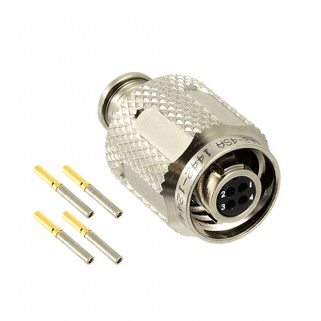
�MKJ5 Plug
Banded & Accessory Thread
MKJ5 Plug (Shown with Banding/Overmolding Attachment)
MKJ5 Plug with Pin Insert (Banding Version)
Dimensions shown in inches (mm)
Specifications and dimensions subject to change
12
www.ittcannon.com
�How to Order — MKJ5 Plug
Banded & Accessory Thread
Product
MKJ5
MKJ5 (Triple Start)
Class:
A-
Environmental Plug with Banding/Overmolding Attachment
B-
Environmental Plug with Threaded Accessory Attachment
Shell Style:
6-
Straight Plug
Material/Plating:
C-
Aluminum/Anodize, Black
F-
Aluminum/Electroless Nickel (RoHS)
K-
Stainless Steel/Passivated (RoHS)
T-
Aluminum/Teflon Nickel (RoHS)
W-
Aluminum/Olive Drab Cadmium
Y-
Stainless Steel/Electroless Nickel, Black (RoHS)
Z-
Aluminum/Zinc Nickel, Black (RoHS)
N-
Stainless Steel/Electroless Nickel (RoHS)
Shell Size/Contact
Arrangement:
A
6
11-19
See Available Layouts on Pages 10–11
Contact Style:
Shell Clocking
P-
Pin, Crimp, Removable
S-
Socket, Crimp, Removable
E-
Pin, Solder Cup, Potted, Non-removable
F-
Socket, Solder Cup, Potted, Non-removable
A-
Normal
B, C, D, E, F
Modification Codes:
- F0
Alternatives
Less Contacts (“F0” not stamped on the connector, but must be included on the P.O.)
- F256
Stainless Steel Hood (Socket contact only)
- 518
Potted connectors with water immersion testing (10-4 Helium leak tested)
Consult factory for other modification codes
MKJ5A6 Environmental Plug with
Banding/Overmolding Attachment
MKJ5B6 Environmental Plug with
Threaded Accessory Attachment
Dimensions shown in inches (mm)
Specifications and dimensions subject to change
www.ittcannon.com
F
13
P
A
**
�MKJ5 Plug
Banded & Accessory Thread
Cable Plug Dimensions
Shell Size
ØA
ØB
C Thread
D Thread Accessory
UNEF-2A
8
0.691
0.317
.5000-.1P-.3L-TS-2B
.3750-32
9
0.787
0.397
.5625-.1P-.3L-TS-2B
.4375-28
10
0.826
0.473
.6250-.1P-.3L-TS-2B
.5000-28
11
0.916
0.519
.6875-.1P-.3L-TS-2B
.5625-24
12
0.982
0.585
.7500-.1P-.3L-TS-2B
.6250-24
15
1.097
0.687
.9375-.1P-.3L-TS-2B
.7500-20
18
1.290
0.884
1.1250-.1P-.3L-TS-2B
.9375-20
19
1.311
0.884
1.1875-.1P-.3L-TS-2B
.9375-20
FRONT VIEW
For all Shell Sizes and Clockings, the Master Keyway remains stationary at top dead center, with minor keys rotating
to achieve alternate clocking positions.
Cable Plug Barrel Clocking Dimensions
MKJ5 PLUG BARREL CLOCKING
Position
K1°
K2°
A (Normal)
150°
210°
B
75°
210°
C
95°
230°
D
140°
275°
E
75°
275°
F
95°
210°
Dimensions shown in inches (mm)
Specifications and dimensions subject to change
14
www.ittcannon.com
�MKJ5 Receptacle
In-Line, Box Mount (Square Flange), Jam Nut Rear Panel Mount
Banded & Accessory Thread
MKJ5 In-Line Receptacle (Shown with Banding/Overmolding Attachment)
MKJ5 In-Line Receptacle with Socket Insert
(Banding Version)
MKJ5 Box Mount Receptacle – Square Flange (Shown with Banding/Overmolding Attachment)
MKJ5 Box Mount Receptacle (Square Flange)
with Socket Insert (Banding Version)
MKJ5 Jam Nut Receptacle – Rear Panel Mount (Shown with Banding/Overmolding Attachment)
MKJ5 Jam Nut Receptacle with Socket Insert
(Banding Version)
Dimensions shown in inches (mm)
Specifications and dimensions subject to change
www.ittcannon.com
15
�How to Order — MKJ5 Receptacle
In-Line, Box Mount (Square Flange), Jam Nut Rear Panel Mount
Banded & Accessory Thread
Product
Class:
Shell Style:
Material/Plating:
Shell Clocking:
Environmental Receptacle with Banding/
Overmolding Attachment
B-
Environmental Receptacle with Threaded Accessory Attachment
1-
In-Line Receptacle
2-
Box Mount Receptacle (Square Flange)
7-
Jam Nut Receptacle-Rear Panel Mount
C-
Aluminum/Anodize, Black
F-
Aluminum/Electroless Nickel (RoHS)
K-
Stainless Steel/Passivated (RoHS)
T-
Aluminum/Teflon Nickel (RoHS)
W-
Aluminum/Olive Drab Cadmium
Y-
Stainless Steel/Electroless Nickel, Black (RoHS)
Z-
Aluminum/Zinc Nickel, Black (RoHS)
N-
Stainless Steel/Electroless Nickel (RoHS)
7
F
11-19
P
A
**
See Available Layouts on Pages 10–11
P-
Pin, Crimp, Removable
S-
Socket, Crimp, Removable
E-
Pin, Solder Cup, Potted, Non-removable
F-
Socket, Solder Cup, Potted, Non-removable
A-
Normal
B, C, D, E, F
Modification Codes:
A
A-
Shell Size/Contact
Arrangement:
Contact Style:
MKJ5
MKJ5 (Triple Start)
- F0
Alternatives
Less Contacts (“F0” not stamped on the connector, but must be included on the P.O.)
- F256
Stainless Steel Hood (Socket contact only)
- 518
Potted connectors with water immersion testing (10-4 Helium leak tested)
Consult factory for other modification codes
MKJ5A1 Environmental Receptacle
In-Line with Banding/Overmolding
Attachment
MKJ5A2 Environmental Box Mount
(Square Flange) Receptacle with
Banding/Overmolding Attachment
MKJ5A7 Environmental Jam Nut
Receptacle with Banding/
Overmolding Attachment
Dimensions shown in inches (mm)
Specifications and dimensions subject to change
16
www.ittcannon.com
�MKJ5 Receptacle
In-Line
Banded and Accessory Thread
Cable Receptacle In-Line Dimensions
Shell Size
ØA
B Flat
C Thread
ØD
F Thread Accessory
UNEF-2A
8
0.540
0.510
.5000-.1P-.3L-TS-2A
0.317
.3750-32
9
0.605
0.575
.5625-.1P-.3L-TS-2A
0.397
.4375-32
10
0.668
0.638
.6250-.1P-.3L-TS-2A
0.473
.5000-28
11
0.730
0.700
.6875-.1P-.3L-TS-2A
0.519
.5625-24
12
0.793
0.763
.7500-.1P-.3L-TS-2A
0.585
.6250-24
15
0.980
0.950
.9375-.1P-.3L-TS-2A
0.687
.7500-20
18
1.165
1.135
1.1250-.1P-.3L-TS-2A
0.884
.9375-20
19
1.235
1.205
1.1875-.1P-.3L-TS-2A
0.884
.9375-20
FRONT VIEW
For all Shell Sizes and Clockings, the Master Keyway remains stationary at top dead center, with minor keys rotating
to achieve alternate clocking positions.
Cable Receptacle In-Line Shell Clocking Dimensions
MKJ5 SHELL CLOCKING
Position
K1°
K2°
A (Normal)
150°
210°
B
75°
210°
C
95°
230°
D
140°
275°
E
75°
275°
F
95°
210°
Dimensions shown in inches (mm)
Specifications and dimensions subject to change
www.ittcannon.com
17
�MKJ5 Receptacle
Box Mount (Square Flange)
Banded and Accessory Thread
Receptacle Box Mount Dimensions
Shell
Size
ØA
B
C,
Basic
Typ
D Thread
ØE
ØF
+.003
G Thread,
Accessory
(UNEF-2A)
H,
Basic
ØJ
8
1.150 0.850 0.660
.5000-.1P-.3L-TS-2A
0.317
0.094
.3750-32
0.660
0.520
9
1.230 0.913 0.723
.5625-.1P-.3L-TS-2A
0.397
0.094
.4375-28
0.723
0.584
10
1.330 0.975 0.785
.6250-.1P-.3L-TS-2A
0.473
0.094
.5000-28
0.785
0.653
11
1.410 1.039 0.848
.6875-.1P-.3L-TS-2A
0.519
0.094
.5625-24
0.848
0.718
12
1.500 1.099 0.909
.7500-.1P-.3L-TS-2A
0.585
0.094
.6250-24
0.909
0.775
15
1.750 1.288 1.058
.9375-.1P-.3L-TS-2A
0.687
0.128
.7500-20
1.058
0.961
18
2.000 1.475 1.255 1.1250-.1P-.3L-TS-2A 0.884
0.128
.9375-20
1.255
1.140
19
2.094 1.537 1.327 1.1875-.1P-.3L-TS-2A 0.884
0.128
.9375-20
1.327
1.230
ØK
0.094
0.128
FRONT VIEW
For all Shell Sizes and Clockings, the Master Keyway remains stationary at top dead center, with minor keys
rotating to achieve alternate clocking positions.
Receptacle Box Mount Shell Clocking Dimensions
MKJ5 SHELL CLOCKING
Panel Cutout Dimensions
Position
K1°
K2°
A (Normal)
150°
210°
B
75°
210°
C
95°
230°
D
140°
275°
E
75°
275°
F
95°
210°
Dimensions shown in inches (mm)
Specifications and dimensions subject to change
18
www.ittcannon.com
�MKJ5 Receptacle
Jam Nut – Rear Panel Mount
Banded and Accessory Thread
Cable Receptacle Jam Nut Dimensions
E
THREAD
(UN-2A)
ØF
G THREAD
ACCESSORY
(UNEF-2A)
H
Flat
ØJ
.5000-.1P-.3L-TS-2A
.5625-32
0.317
.3750-32
0.543
0.572
.5625-.1P-.3L-TS-2A
.6875-28
0.397
.4375-28
0.669
0.698
0.661
.6250-.1P-.3L-TS-2A
.6875-28
0.473
.5000-28
0.669
0.698
0.721
.6875-.1P-.3L-TS-2A
.7500-28
0.519
.5625-24
0.729
0.760
1.035
0.784
.7500-.1P-.3L-TS-2A
.8125-28
0.585
.6250-24
0.792
0.822
1.173
0.970
.9375-.1P-.3L-TS-2A
1.0000-28
0.687
.7500-20
0.978
1.010
1.389
1.359
1.147
1.1250-.1P-.3L-TS-2A
1.1875-28
0.884
.9375-20
1.155
1.198
1.450
1.420
1.221
1.1875-.1P-.3L-TS-2A
1.2500-28
0.884
.9375-20
1.223
1.385
Shell
Size
DIA.
ØA
ØB
FLATS
C
Flat
D Thread
8
0.760
0.730
0.535
9
0.880
0.850
0.661
10
0.880
0.850
11
0.955
0.925
12
1.060
15
1.203
18
19
FRONT VIEW
For all Shell Sizes and Clockings, the Master Keyway remains stationary at top dead center, with minor keys
rotating to achieve alternate clocking positions.
Cable Receptacle Jam Nut Shell Clocking Dimensions
MKJ5 SHELL CLOCKING
Position
K1°
K2°
A (Normal)
150°
210°
B
75°
210°
C
95°
230°
D
140°
275°
E
75°
275°
F
95°
210°
Dimensions shown in inches (mm)
Specifications and dimensions subject to change
www.ittcannon.com
Panel Cutout Dimensions
19
�MKJ5 Receptacle
Box Mount (Square Flange), Jam Nut Rear Panel Mount
Potted, PCB & Solder Cup
MKJ5 Box Mount Receptacle – Square Flange – PCB Mount
MKJ5 Box Mount Receptacle (Square Flange)
with PCB Mount Socket Insert
MKJ5 Jam Nut Receptacle – Rear Panel Mount – PCB Mount
MKJ5 Jam Nut Receptacle
with PCB Mount Socket Insert
Dimensions shown in inches (mm)
Specifications and dimensions subject to change
20
www.ittcannon.com
�How to Order — MKJ5 Receptacle
Box Mount (Square Flange), Jam Nut Rear Panel Mount
Potted, PCB & Solder Cup
Product
MKJ5
MKJ5 (Triple Start)
Class:
C-
Potted Receptacle-PC/Flex/Solder
Shell Style:
2-
Box Mount Receptacle (Square Flange)
7-
Jam Nut Receptacle-Rear Panel Mount
C-
Aluminum/Anodize, Black
F-
Aluminum/Electroless Nickel (RoHS)
K-
Stainless Steel/Passivated (RoHS)
T-
Aluminum/Teflon Nickel (RoHS)
W-
Aluminum/Olive Drab Cadmium
Y-
Stainless Steel/Electroless Nickel, Black (RoHS)
Z-
Aluminum/Zinc Nickel, Black (RoHS)
N-
Stainless Steel/Electroless Nickel (RoHS)
Material/Plating:
Shell Size/Contact
Arrangement:
C
2
See Available Layouts on Pages 10–11
Contact Style:
Shell Clocking:
B-
Pin, PC Tail, .109 Extension, Potted, Non-removable
D-
Socket, PC Tail, .109 Extension, Potted, Non-removable
E-
Pin, Solder Cup, Potted, Non-removable
F-
Socket, Solder Cup, Potted, Non-removable
A-
Normal
B, C, D, E, F
Modification Codes:
- F256
- 518
Alternatives
Stainless Steel Hood (Socket contact only)
Potted connectors with water immersion testing (10-4 Helium leak tested)
Consult factory for other modification codes
MKJ5C2 Potted Receptacle Box
Mount (Square Flange) with
PCB Mount
MKJ5C7 Potted Receptacle
Jam Nut with PCB Mount
Dimensions shown in inches (mm)
Specifications and dimensions subject to change
www.ittcannon.com
21
F
11-19
B
A
**
�MKJ5 Receptacle
Box Mount (Square Flange)
Potted, PCB & Solder Cup
Receptacle Box Mount Dimensions
Shell
Size
ØA
B
C,
Basic
Typ
H,
Basic
ØJ
.SIZE 23
.018/.022
0.660
0.520
0.723
0.584
SIZE 20HD
.024/.028
0.785
0.653
0.848
0.718
SIZE 16
.060/.064
0.909
0.775
1.058
0.961
SIZE 12
.092/.096
1.255
1.140
1.327
1.230
D Thread
ØE
ØF
ØG
8
1.150 0.850 0.660
.5000-.1P-.3L-TS-2A
0.330
0.094
9
1.230 0.913 0.723
.5625-.1P-.3L-TS-2A
0.432
0.094
10
1.330 0.975 0.785
.6250-.1P-.3L-TS-2A
0.493
0.094
11
1.410 1.039 0.848
.6875-.1P-.3L-TS-2A
0.551
0.094
12
1.500 1.099 0.909
.7500-.1P-.3L-TS-2A
0.620
0.094
15
1.750 1.288 1.058
.9375-.1P-.3L-TS-2A
0.703
0.128
18
2.000 1.475 1.255 1.1250-.1P-.3L-TS-2A 0.863
0.128
19
2.094 1.537 1.327 1.1875-.1P-.3L-TS-2A 0.912
0.128
ØK
0.094
0.128
PCB VERSION
PCB VERSION
SOLDER CUP VERSION
FRONT VIEW
CUP VERSION
For all Shell Sizes and Clockings, the Master Keyway remains SOLDER
stationary
at top dead center, with minor keys
rotating to achieve alternate clocking positions.
Receptacle Box Mount Shell Clocking Dimensions
MKJ5 SHELL CLOCKING
Panel Cutout Dimensions
Position
K1°
K2°
A (Normal)
150°
210°
B
75°
210°
C
95°
230°
D
140°
275°
E
75°
275°
F
95°
210°
Dimensions shown in inches (mm)
Specifications and dimensions subject to change
22
www.ittcannon.com
�MKJ5 Receptacle
Jam Nut Rear Panel Mount
Potted, PCB & Solder Cup
Receptacle Jam Nut Rear Mount Dimensions
E
THREAD
(UN-2A)
ØF
ØG
.5000-.1P-.3L-TS-2A
.5625-32
0.330
.5625-.1P-.3L-TS-2A
.6875-28
0.432
.SIZE 23
.018/.022
0.661
.6250-.1P-.3L-TS-2A
.6875-28
0.493
0.721
.6875-.1P-.3L-TS-2A
.7500-28
0.551
1.035
0.784
.7500-.1P-.3L-TS-2A
.8125-28
0.620
1.173
0.970
.9375-.1P-.3L-TS-2A
1.0000-28
0.703
1.389
1.359
1.147
1.1250-.1P-.3L-TS-2A
1.1875-28
0.863
1.450
1.420
1.221
1.1875-.1P-.3L-TS-2A
1.2500-28
0.912
Shell
Size
ØA
B
FLATS
C
Flat
D Thread
8
0.760
0.730
0.535
9
0.880
0.850
0.661
10
0.880
0.850
11
0.955
0.925
12
1.060
15
1.203
18
19
H
Flat
ØJ
0.543
0.572
0.669
0.698
SIZE 20HD
.024/.028
0.669
0.698
0.729
0.760
SIZE 16
.060/.064
0.792
0.822
0.978
1.010
SIZE 12
.092/.096
1.155
1.198
1.223
1.385
PCB VERSION
PCB VERSION
SOLDER CUP VERSION
FRONT VIEW
SOLDER CUP VERSION
For all Shell Sizes and Clockings, the Master Keyway remains stationary at top dead center, with minor keys
rotating to achieve alternate clocking positions.
Panel Cutout Dimensions
Receptacle Jam Nut Shell Clocking Dimensions
MKJ5 SHELL CLOCKING
Position
K1°
K2°
A (Normal)
150°
210°
B
75°
210°
C
95°
230°
D
140°
275°
E
75°
275°
F
95°
210°
Dimensions shown in inches (mm)
Specifications and dimensions subject to change
www.ittcannon.com
23
�MKJ5 Weight Charts
MKJ5 Connector
Weight in Grams
Pin
Layout
Plug
Jam Nut
Jam Nut
Receptacle Receptacle
Crimp
PCB
MKJ5 Connector
Weight in Grams
Square
Flange
Receptacle
Crimp
Square
Flange
Receptacle
PCB
Socket
Layout
Plug
Jam Nut
Jam Nut
Receptacle Receptacle
Crimp
PCB
Square
Flange
Receptacle
Crimp
Square
Flange
Receptacle
PCB
8-1P
8.4
6.9
7.0
6.7
5.7
8-1S
8.8
7.2
7.0
6.2
6.4
8-23P
8.3
6.7
6.6
6.7
5.5
8-23S
8.8
7.2
7.2
7.4
6.1
8-4P
8.1
6.8
6.7
6.8
5.6
8-4S
8.7
7.1
7.4
7.6
6.3
8-6P
8.2
6.9
7.0
6.9
5.7
8-6S
8.7
7.1
7.5
6.1
6.4
8-7P
8.2
7.0
6.9
7.0
5.8
8-7S
8.8
7.2
7.0
7.2
5.9
9-1P
10.7
9.2
9.2
7.0
7.9
9-1S
11.7
9.8
9.8
7.6
8.5
9-25P
10.8
9.3
9.2
7.1
8.0
9-25S
11.4
9.5
9.6
7.5
8.2
9-10P
11.1
9.2
9.2
7.0
7.9
9-10S
11.3
9.4
9.4
7.2
8.1
10-2P
12.9
9.8
9.9
8.7
9.2
10-2S
13.0
9.8
9.9
9.6
10.0
10-28P
13.2
9.9
10.1
9.2
9.9
10-28S
15.8
10.3
10.4
10.0
10.5
10-13P
12.4
9.6
9.7
8.2
8.6
10-13S
12.7
10.2
9.8
8.9
9.4
11-4P
15.1
11.0
12.0
10.2
11.2
11-4S
15.4
13.0
13.4
11.2
12.2
11-210P
15.0
11.5
12.2
9.7
10.7
11-210S
15.3
12.8
13.7
11.1
12.0
11-19P
15.3
11.2
12.0
9.4
10.4
11-19S
15.7
12.0
13.0
10.2
11.2
12-2P
17.1
13.7
15.2
11.6
12.0
12-2S
18.1
14.8
16.8
13.3
13.5
12-5P
17.4
13.7
16.1
12.1
13.0
12-5S
17.7
15.2
17.6
13.1
14.0
12-26P
17.3
13.2
13.2
10.4
11.2
12-26S
17.4
13.5
14.4
10.3
11.2
15-2P
20.5
20.2
21.8
16.9
19.5
15-2S
22.1
21.8
23.3
18.6
21.0
15-3P
21.6
21.3
22.9
17.9
20.6
15-3S
22.3
22.9
24.4
19.7
22.1
15-7P
22.0
21.6
23.1
18.5
20.9
15-7S
22.9
24.0
25.5
21.1
23.5
15-220P
20.9
21.1
23.9
18.4
21.8
15-220S
23.5
23.5
26.0
21.4
23.7
15-37P
20.2
20.2
20.4
17.0
19.6
15-37S
21.4
22.4
23.9
19.2
21.6
18-12P
30.8
32.4
32.6
27.8
31.5
18-12S
32.4
34.1
32.6
29.6
32.5
18-5P
32.2
33.8
33.2
29.4
32.9
18-5S
33.2
34.9
33.4
30.4
33.3
18-235P
30.3
31.1
29.3
28.8
30.8
18-235S
32.1
33.6
32.8
28.1
31.7
18-55P
27.5
28.0
28.0
25.3
27.0
18-55S
30.2
30.4
29.0
26.0
28.5
19-85P
31.0
29.8
29.5
28.4
30.9
19-85S
32.1
32.6
35.7
28.8
35.6
Dimensions shown in inches (mm)
Specifications and dimensions subject to change
24
www.ittcannon.com
�MKJ Accessories
Format Sheet-Tooling and Contacts MKJ
Crimp Contacts
Pin Contacts (Size 23)
Socket contacts (Size 23)
030-9649-000
031-9750-000
Contact Area Plating:
50 Micro inches Gold over Nickel
Accommodates Sizes #22-28 AWG Wire
Crimp Tool
Contact Crimp Tool
Locator
995-0002-293
995-0002-297
Contact Insertion/Extraction Tools
Insertion Tool
995-0002-295
Extraction Tool
995-0002-294
Banding Tools
Hand banding Tool
1/8” bands (100 pk)
995-0002-298
995-0002-299
Banding Tools
PART NUMBER
USE ON JAMNUT
SIZE / PN
317-2187-000
MKJ1 (6) MKJ0 (7)
317-2187-001
MKJ1 (7) MKJ0 (9)
317-2187-002
MKJ1 (9)
317-2187-003
MKJ1 (13)
317-2187-006
MKJ0 (6)
317-2187-007
MKJ0 (12)
Dimensions shown in inches (mm)
Specifications and dimensions subject to change
www.ittcannon.com
25
�MKJ Accessories
Backshells
MKJB
S- 7 - 6 - W
Shell Material: 6061-T6 Aluminum
Clamp
Straight
90°
Backshell Designator Table
Backshell
Designator
1
2
Shell
Style
MKJ0,
MKJ1,
MKJ3,
MKJ4
MKJ0,
MKJ1,
MKJ3,
MKJ4
Shell
Size
(05)
Straight
(06)
Straight
3
4
MKJ5
MKJ0,
MKJ1,
MKJ3,
MKJ4
(08)
Straight
(07)
Straight
5
MKJ5
MKJ0,
MKJ1,
MKJ3,
MKJ4
(09)
Straight
(08)
Straight
6
MKJ5
MKJ0,
MKJ1,
MKJ3,
MKJ4
(10)
Straight
(09)
Straight
7
MKJ5
MKJ0,
MKJ1,
MKJ3,
MKJ4
(11)
Straight
(10)
Straight
8
MKJ5
MKJ0,
MKJ1,
MKJ3,
MKJ4
MKJ5
(12)
Straight
(12)
Straight
(13)
Straight
Heat Shrink Boot
Material: Fluid resistant elastomer
MKJ Heat Shrink Boot P/N's - Straight
Shell Size
ITT P/N
5, 6, 7
980-2010-017
8, 9
980-2010-018
10, 11, 12, 13
980-2010-019
Adhesive: Polyamide hot melt
MKJ Heat Shrink Boot P/N's - 90°
Shell Size
ITT P/N
5, 6, 7
980-2010-020
8, 9
980-2010-021
10, 11, 12, 13 980-2010-022
Metal Dust Caps
MKJ Aluminum Dustcap Designator- Talking Dog
MKJD
Shell Style
0, 1, 3, 4, 5
Shell Size
5, 6, 7, 8, 9,
11, 12 , 13
Shell Material: Alluminum Alloy
1- 7 - P - F
Plating
W= OD Cad
F = Nickel
Z = Black Zinc Nickel
Gender
P= Plug
R= Receptacle
No Size 11 or 12 dustcaps are available on MKJ1
No size 11 or 13 dustcaps are available on MKJ0, MKJ3, & MKJ4
No size 5, 6, 7, or 13 dustcaps are available on MKJ5
Dimensions shown in inches (mm)
Specifications and dimensions subject to change
26
www.ittcannon.com
�Cables to Outfit Your MKJ Connector
Value-Added MKJ Series Cabling Solutions from ITT Cannon
Let ITT Cannon complete your MKJ
solution with our custom cable
products. A complement to the
reduction in size of the connectors is
the reduction in weight and thickness
in cabling. Choose from several
available options to help customize
your application. Improving on our
high reliability connectors, we offer
overmolds that are suitable for
military requirements in harsh
environments.
Dimensions shown in inches (mm)
Specifications and dimensions subject to change
www.ittcannon.com
27
�About ITT Cannon
ITT Inc. is a diversified leading manufacturer of highly
engineered critical components and customized technology
solutions for industrial end-markets in energy infrastructure,
electronics, aerospace and transportation. Building on its
heritage of innovation, ITT partners with its customers to deliver
enduring solutions to the key industries that underpin our
modern way of life. Founded in 1920, ITT is headquartered in
White Plains, N.Y., with employees in more than 35 countries
and sales from a total of 125 countries.
strength and our advanced manufacturing facilities allows
ITT to offer products at market driven prices. Our capabilities,
especially in robotics, computerized precision tooling, Kaizen
Project Management, Six Sigma tools and testing, give ITT
the most optimized global manufacturing footprint in the
interconnect industry.
The Custom Difference
As the industry leader in harsh environment interconnect
applications, ITT’s world class engineering teams will work
directly with our customers to design and develop cost effective
solutions for their applications. In many cases we may modify
one of our standard designs to ensure a highly reliable solution
where timing is critical. When custom connectors are required,
we collaborate with clients and partners with a goal to design
the most reliable, cost-effective solution possible. As professional
consultants, our Engineering teams will provide a thorough
systems and mechanical analysis of any proposed solution.
These analyses provide our customers with sophisticated
electrical signal and mechanical characterizations to determine
the best solution for their application.
Our connector portfolio remains the most extensive in the
industry, offering a reliable and cost effective range of
interconnect solutions. Continuous investment in technology
and research & development have enabled ITT to provide new,
innovative products and solutions to markets including:
• Commercial Aviation
• Defense
• Oil & Gas
•Industrial
• Medical
• Space Exploration
When you specify a Cannon connector, you can rely on
products that are designed, developed, and manufactured
to the highest quality and reliability standards. This tradition of
excellence is based on ITT’s corporate culture of operating its
businesses under the principles of Six Sigma. At ITT, Six Sigma
is not just a quality philosophy but a complete corporate
culture that drives the entire business. Our Value Based
Management and Value Based Product Development
systems are two cornerstones that allow for the
development of both leadership and product engineering
principles, ensuring our industry leading products are developed
to the accepted market driven lead times. These principles have
allowed ITT to become the market leader in all of our business
portfolios.
RoHS Compliance Information
ITT has implemented a strict parts control plan for all ITT
electronics plants worldwide that allows the Cannon product
portfolio to meet the requirements of the European Union
Directive 2002/95/EC better known as the Reduction of
Hazardous Substances initiative. As appropriate, specific
Cannon products may be ordered with an R prefix number
which insures our customers will receive RoHS compliant
parts for their commercial electronics applications and
equipment. Since most RoHS hazardous substances center
around specific metal plating and lead solder coatings, ITT’s
products for RoHS compliance are available in the following
plating finishes: electroless nickel, stainless steel, anodize
over aluminum and gold plating. It should be noted that gold
plating would be recommended as the replacement for
tin-lead solder when ordering board mount connectors.
Six Sigma Manufacturing
ITT Cannon operates manufacturing facilities in the United
States, Germany, Italy, Mexico, China and Japan, allowing
ITT to offer global capabilities to our customers. Our fullyintegrated, world class facilities use the latest manufacturing
technologies including automated and robotic maching centers,
Super Market manufacturing cells, Kanban pull systems,
and automated, electrical, mechanical and optical test and
inspection equipment. The combination of our manufacturing
Dimensions shown in inches (mm)
Specifications and dimensions subject to change
28
www.ittcannon.com
�Product Safety
no solder blobs, loose strands, conducting lubricants, swarf, or
any other undesired conducting particles. Circuit resistance and
continuity check should be made to make certain that there are no
high resistance joints or spurious conducting paths. Always use the
correct application tools as specified in the Data Sheet/Catalog. Do
not permit untrained personnel to wire, assemble or tamper with
connectors. For operation voltage please see appropriate national
regulations.
1. Material Content and Physical Form
Electrical connectors do not usually contain hazardous materials.
They contain conducting and non-conducting materials and can
be divided into two groups.
a) Printed circuit types and low cost audio types which employ
all plastic insulators and casings.
b) Rugged, Fire Barrier and High Reliability types with metal
casings and either natural rubber, synthetic rubber, plastic or
glass insulating materials. Contact materials vary with type of
connector and also application and are usually manufactured
from either: Copper, copper alloys, nickel, alumel, chromel or
steel. In special applications, other alloys may be specified.
Important General Information
(i) Air and creepage paths/Operating voltage. The admissible
operating voltages depend on the individual applications and the
valid national and other applicable safety regulations. For this
reason the air and creepage path data are only reference values.
Observe reduction of air and creepage paths due to PC board
and/or harnessing.
(ii) Temperature
All information given are temperature limits. The operation
temperature depends on the individual application.
(iii) Other important information
ITT Cannon continuously endeavors to improve their products.
Therefore, Cannon products may deviate from the description,
technical data and shape as shown in this catalog and data
sheets.
2. Fire Characteristics And Electric Shock Hazard
There is no fire hazard when the connector is correctly wired and
used within the specified parameters. Incorrect wiring or assembly
of the connector or careless use of metal tools or conductive fluids,
or transit damage to any of the component parts may cause electric
shock or burns. Live circuits must not be broken by separating
mated connectors as this may cause arcing, ionization and burning.
Heat dissipation is greater at maximum resistance in a circuit.
Hot spots may occur when resistance is raised locally by damage,
e.g. cracked or deformed contacts, broken strands of wire. Local
overheating may also result from the use of the incorrect application
tools or from poor quality soldering or slack screw terminals.
Overheating may occur if the ratings in the product Data Sheet/
Catalog are exceeded and can cause breakdown of insulation and
hence electric shock. If heating is allowed to continue it intensifies
by further increasing the local resistance through loss of temper of
spring contacts, formation of oxide film on contacts and wires and
leakage currents through carbonization of insulation and tracking
paths. Fire can then result in the presence of combustible materials
and this may release noxious fumes. Overheating may not be visually
apparent. Burns may result from touching overheated components.
ITT Cannon, is a division of ITT Inc. who manufactures the
highest quality products available in the marketplace; however
these products are intended to be used in accordance with
the specifications in this publication. Any use or application
that deviates from the stated operating specifications is not
recommended and may be unsafe. No information and data
contained in this publication shall be construed to create any liability
on the part of ITT Cannon. Any new issue of this publication shall
automatically invalidate and supersede any and all previous issues.
3. Handling
Care must be taken to avoid damage to any component parts of
electrical connectors during installation and use. Although there are
normally no sharp edges, care must be taken when handling certain
components to avoid injury to fingers. Electrical connectors may
be damaged in transit to the customers, and damage may result in
creation of hazards. Products should therefore be examined prior to
installation/use and rejected if found to be damaged.
4. Disposal
Incineration of certain materials may release noxious or even toxic
fumes.
5. Application
Connectors with exposed contacts should not be selected for use
on the current supply side of an electrical circuit, because an electric
shock could result from touching exposed contacts on an unmated
connector. Voltages in excess of 30 V ac or 42.5 V dc are potentially
hazardous and care should be taken to ensure that such voltages
cannot be transmitted in any way to exposed metal parts of the
connector body. The connector and wiring should be checked,
before making live, to have no damage to metal parts or insulators,
Dimensions shown in inches (mm)
Specifications and dimensions subject to change
www.ittcannon.com
29
�Meet Some of Our Most
Innovative Connectors
D-Subminiature Connectors
Originally designed for aircraft radio
systems, Cannon‘s D-Subminiature
Connector became the first multi-purpose
interconnect solution of its kind, ideal for
multiple markets and applications. From
rocket launches and satellite systems, to
rugged military transports and commercial
avionics, the D-Subminiature’s versatility
has made this Cannon invention the most
widely used connector in the world.
Rack & Panel Connectors
Pioneered by Cannon during the 1930s,
our Rack & Panel Connectors offer an
unmatched variety of shell configurations
and insert arrangements, as well as
materials, plating and contact options.
Today, we are recognized as an industry
leader, offering an unparalleled range of
off-the-shelf and custom Rack & Panel
products to align with customer needs.
Microminiature Connectors
Developed first by Cannon in the 1960s,
Microminiature Connectors offer high
performance and reliability with exceptional
versatility. Available in rectangular, circular
and strip-style configurations, our highly
engineered Microminiature connector
products meet critical customer demands
in multiple applications across the
Aerospace & Defense industry
Dimensions shown in inches (mm)
Specifications and dimensions subject to change
30
www.ittcannon.com
�Notes:
Dimensions shown in inches (mm)
Specifications and dimensions subject to change
www.ittcannon.com
31
�Connect with your ITT Cannon
representative today or visit us at
www.ittcannon.com
Connect with the experts.
Whether communicating with our soldiers in the field or
with first responders saving lives, ITT Cannon connects vital
information with those who need it.
CHINA—Shenzhen City
GERMANY—Weinstadt
HONG KONG
ITALY—Lainate
+86.755.2726.7888
+49.7151.699.0
+852.2732.2720
+39.02938721
JAPAN—Kanagawa
KOREA—Seoul
TAIWAN—Taipei
UK—Basingstoke
+81.462.57.2010
+82.2.7027111
+886.2.25452020
USA—Watertown, CT
+1.860.274.9681
+44.1256.311200
USA—Irvine, CA
+1.800.854.3028
The “ITT Engineered Blocks“ symbol, “Engineered for life," “ITT” and “Cannon“ are registered trademarks of ITT Inc. Specification
and other data are based on information available at the time of printing, and are subject to change without notice.
©2019 ITT Inc.
ITT Cannon MKJ5 Catalog | 072019
�


 工商网监
湘ICP备2023018690号
工商网监
湘ICP备2023018690号
