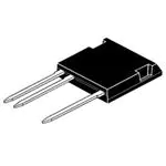
CS 20-22moF1
VDRM = VRRM = 2200 V
IT(AV)
= 18 A
= 200 A
ITSM
High Voltage
Phase Control Thyristor
in High Voltage
ISOPLUS i4-PAC™
Part number
CS 20-22moF1
5
1
2
5
1
2
Features / Advantages:
Applications:
Package: i4-Pac
• high voltage thyristor
- for line frequency
- chip technology for long term stability
• ISOPLUS i4-PAC™
high voltage package
- isolated back surface
- enlarged creepage towards heatsink
- enlarged creepage between high
voltage pins
- application friendly pinout
- high reliability
- industry standard outline
• controlled rectifiers
- power supplies
- drives
• AC switches
• capacitor discharge control
- flash tubes
- X-ray and laser generators
• Isolation Voltage: 3000 V~
• Industry convenient outline
• RoHS compliant
• Epoxy meets UL 94V-0
• Soldering pins for PCB mounting
• Backside: DCB ceramic
• Reduced weight
• Advanced power cycling
Disclaimer Notice
Information furnished is believed to be accurate and reliable. However, users should independently
evaluate the suitability of and test each product selected for their own applications. Littelfuse products are not designed for,
and may not be used in, all applications. Read complete Disclaimer Notice Disclaimer Notice at www.littelfuse.com/disclaimer-electronics.
IXYS reserves the right to change limits, test conditions and dimensions.
© 2022 IXYS All rights reserved
20220623b
1-3
�CS 20-22moF1
Thyristor
Ratings
Symbol
Definitions
Conditions
min.
VDRM, RRM
max. repetitive blocking voltage
IT(AV)
IT(AV)
average forward current
sine 180°
square; d = 1/3
TC =
TC =
ITSM
max. surge on-state current
sine 180°; t = 10 ms; VR = 0 V
TVJ =
(di/dt)cr
critical rate of rise of current
TVJ = TVJM
f = 50 Hz; tp = 200 µs
repetitive, IT = 40 A
VD = 2/3 VDRM
IG = 0.45 A
diG /dt = 0.45 A/µs
non repetitive, IT = 20 A
typ.
max.
Unit
2200
V
90°C
90°C
18
16
A
A
25°C
200
A
100
A/µs
250
A/µs
2500
V/µs
1.5
V
V
(dv/dt)cr
critical rate of rise of voltage
TVJ = TVJM; VD = 2/3 VDRM
RGK = ∞; method 1 (linear voltage rise)
VT
forward voltage
IT = 20 A
TVJ = 25°C
TVJ = 125°C
VGT
IGT
gate trigger voltage
gate trigger current
VD = 6 V
TVJ = 25°C
2.3
250
V
mA
VGD
IGD
gate non-trigger voltage
gate non-trigger current
VD = 2/3 VDRM
TVJ = 125°C
0.2
5
V
mA
IL
latching current
tp = 10 µs; VD = 6 V
IG = 0.45 A; diG /dt = 0.45 A/µs
TVJ = 25°C
500
mA
IH
holding current
VD = 6 V; RGK = ∞
TVJ = 25°C
150
mA
tgd
gate controlled delay time
VD = ½ VDRM
IG = 0.45 A; diG /dt = 0.45 A/µs
TVJ = 25°C
2
IR
ID
reverse current
drain current
VR = VRRM; VD = VDRM
TVJ = 25°C
TVJ = 125°C
2
RthJC
thermal resistance juntion to case
DC current
RthCH
thermal resistance case to heatsink DC current
IXYS reserves the right to change limits, test conditions and dimensions.
© 2022 IXYS All rights reserved
1.3
1.3
0.15
µs
50
µA
mA
0.92
K/W
K/W
20220623b
2-3
�CS 20-22moF1
Package
I4-Pac
Ratings
Symbol
Definitions
Conditions
IRMS
RMS current
per terminal
TVJ
virtual junction temperature
Top
Tstg
min.
max.
Unit
70
A
-40
150
°C
operation temperature
-40
125
°C
storage temperature
-40
150
°C
Weight
typ.
5.5
FC
mounting force with clip
dSpp/App
dSpb/Apb
creepage distance on surface | striking distance through air
VISOL
isolation voltage
20
t = 1 second
t = 1 minute
terminal to terminal
terminal to backside
50/60 Hz, RMS, IISOL < 1 mA
g
120
N
7.2
5.1
mm
mm
3000
V
2500
V
Product Marking
UL
Logo
IXYS
®
ISOPLUS®
Part Number
Date Code
XXXXXXXXX
yywwZ
1234
Location
Lot#
Dimensions in mm (1 mm = 0.0394")
A2
E1
D
D3
D1
R
Q
E
D2
A
L
L1
b4
c
1 2
3x b
5
A1
3x b2
e1
e
Dim.
A
A1
A2
b
b2
b4
c
D
D1
D2
D3
E
E1
e
e1
L
L1
Q
R
W
Millimeter
min
max
4.83
5.21
2.59
3.00
1.17
2.16
1.14
1.40
1.47
1.73
2.54
2.79
0.51
0.74
20.80
21.34
14.99
15.75
1.65
2.03
20.30
20.70
19.56
20.29
16.76
17.53
3.81 BSC
11.43 BSC
19.81
21.34
2.11
2.59
5.33
6.20
4.57
2.54
0.10
-
Inches
min
max
0.190
0.205
0.102
0.118
0.046
0.085
0.045
0.055
0.058
0.068
0.100
0.110
0.020
0.029
0.819
0.840
0.590
0.620
0.065
0.080
0.799
0.815
0.770
0.799
0.660
0.690
0.150 BSC
0.450 BSC
0.780
0.840
0.083
0.102
0.210
0.244
0.100
0.180
0.004
-
Die konvexe Form des Substrates ist typ. < 0.05 mm über
der Kunststoffoberfläche der Bauteilunterseite
W
IXYS reserves the right to change limits, test conditions and dimensions.
© 2022 IXYS All rights reserved
The convexbow of substrate is typ. < 0.05 mm over plastic
surface level ofdevice bottom side
20220623b
3-3
�
很抱歉,暂时无法提供与“CS20-22MOF1”相匹配的价格&库存,您可以联系我们找货
免费人工找货- 国内价格 香港价格
- 250+263.83436250+32.84490
- 国内价格 香港价格
- 1+258.395391+32.16780
- 4+255.185514+31.76820
- 15+252.0648015+31.37970
- 40+249.8357140+31.10220
- 100+246.09085100+30.63600
- 国内价格 香港价格
- 1+262.764401+32.71170
- 4+259.376194+32.28990
- 15+256.2554715+31.90140
- 40+253.9372340+31.61280
- 100+250.19237100+31.14660
