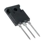
IXKR 40N60C
CoolMOS™ 1) Power MOSFET
in ISOPLUS247TM Package
N-Channel Enhancement Mode
Low RDSon, High VDSS MOSFET
Package with Electrically Isolated Base
D
VDSS
ID25
RDS(on)
600 V
38 A
70 mΩ
Ω
ISOPLUS 247TM
E153432
G
G
D
Preliminary data
S
S
G = Gate
D = Drain
Isolated base
S = Source
Features
MOSFET
Symbol
Conditions
VDSS
TVJ = 25°C to 150°C
Maximum Ratings
VGS
ID25
ID90
TC = 25°C
TC = 90°C
dv/dt
VDS < VDSS; IF ≤ 50A;⎮diF/dt⎮≤ 100A/µs
TVJ = 150°C
EAS
EAR
ID = 10 A; L = 36 mH; TC = 25°C
ID = 20 A; L = 5 µH; TC = 25°C
Symbol
Conditions
600
V
±20
V
38
25
A
A
6
V/ns
1.8
1
J
mJ
Characteristic Values
(TVJ = 25°C, unless otherwise specified)
min.
typ. max.
RDSon
VGS = 10 V; ID = ID90
VGSth
VDS = 20 V; ID = 3 mA;
IDSS
VDS = VDSS; VGS = 0 V; TVJ = 25°C
TVJ = 125°C
70 mΩ
2.1
3.9
60
V
25 µA
µA
• ISOPLUS247™ package with DCB Base
- Electrical isolation towards the heatsink
- Low coupling capacitance to the heatsink for
reduced EMI
- High power dissipation
- High temperature cycling capability
of chip on DCB
- JEDEC TO-247AD compatible
- Easy clip assembly
• fast CoolMOS™ 1) power MOSFET 3rd
generation
- High blocking capability
- Low on resistance
- Avalanche rated for unclamped
inductive switching (UIS)
- Low thermal resistance
due to reduced chip thickness
• Enhanced total power density
Applications
•
•
•
•
•
Switched mode power supplies (SMPS)
Uninterruptible power supplies (UPS)
Power factor correction (PFC)
Welding
Inductive heating
1)
CoolMOS™ is a trademark of
Infineon Technologies AG.
IGSS
VGS = ±20 V; VDS = 0 V
100 nA
Qg
Qgs
Qgd
VGS= 10 V; VDS = 350 V; ID = 50 A
250
25
120
nC
nC
nC
td(on)
tr
td(off)
tf
VGS= 10 V; VDS = 380 V;
ID = 50 A; RG = 1.8 Ω
20
30
110
10
ns
ns
ns
ns
VF
(reverse conduction) IF = 20 A; VGS = 0 V
RthJC
IXYS reserves the right to change limits, test conditions and dimensions.
© 2008 IXYS All rights reserved
0.9
1.1
V
0.45 K/W
20080523a
1-2
�IXKR 40N60C
ISOPLUS247TM OUTLINE
Component
Symbol
Conditions
VISOL
IISOL ≤ 1 mA; 50/60 Hz
TVJ
Tstg
TL
1.6 mm from case for 10 s
FC
mounting force with clip
Symbol
Conditions
Cp
coupling capacity between shorted
pins and mounting tab in the case
RthCH
with heatsink compound
Weight
Maximum Ratings
2500
V~
-40...+150
-40...+125
°C
°C
300
°C
20 ... 120
N
Characteristic Values
min.
typ. max.
30
pF
0.25
K/W
6
g
The convex bow of substrate is typ. < 0.04 mm over plastic surface level
of device bottom side
This drawing will meet all dimensions requirement of JEDEC outline
TO-247 AD except screw hole and except Lmax.
20080523a
© 2008 IXYS All rights reserved
2-2
�Disclaimer Notice - Information furnished is believed to be accurate and reliable. However, users should independently
evaluate the suitability of and test each product selected for their own applications. Littelfuse products are not designed for,
and may not be used in, all applications.Read complete Disclaimer Notice at www.littelfuse.com/disclaimer-electronics.
�
很抱歉,暂时无法提供与“IXKR40N60C”相匹配的价格&库存,您可以联系我们找货
免费人工找货