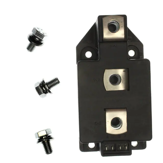
MCC 250 MCD 250
Thyristor Modules Thyristor/Diode Modules
ITRMS = 2x450 A ITAVM = 2x287 A VRRM = 800-1800 V
3 2 7 6 1 5 4
VRSM VDSM V 900 1300 1500 1700 1900
VRRM VDRM V 800 1200 1400 1600 1800
Type Version 1 MCC MCC MCC MCC MCC 250-08io1 250-12io1 250-14io1 250-16io1 250-18io1 Version 1 MCD MCD MCD MCD MCD 250-08io1 250-12io1 250-14io1 250-16io1 250-18io1
Symbol ITRMS, IFRMS ITAVM, IFAVM ITSM, IFSM
Conditions TVJ = TVJM TC = 85°C; 180° sine TVJ = 45°C VR = 0 TVJ = TVJM VR = 0 t = 10 ms (50 Hz), sine t = 8.3 ms (60 Hz), sine t = 10 ms (50 Hz), sine t = 8.3 ms (60 Hz), sine t = 10 ms (50 Hz), sine t = 8.3 ms (60 Hz), sine t = 10 ms (50 Hz), sine t = 8.3 ms (60 Hz), sine
Maximum Ratings 450 287 9000 9600 7800 8500 405 000 380 000 304 000 300 000 100 A A A A A A A2s A2s A2s A2s A/µs MCC
3
671
542
3
1
5 42
∫i2dt
MCD
TVJ = 45°C VR = 0 TVJ = TVJM VR = 0
Features • International standard package • Direct copper bonded Al2O3 -ceramic base plate • Planar passivated chips • Isolation voltage 3600 V~ • UL registered, E 72873 • Keyed gate/cathode twin pins Applications • Motor control • Power converter • Heat and temperature control for industrial furnaces and chemical processes • Lighting control • Contactless switches Advantages • Space and weight savings • Simple mounting • Improved temperature and power cycling • Reduced protection circuits
(di/dt)cr
TVJ = TVJM; repetitive, IT = 860 A f = 50 Hz; tP = 200 µs VD = 2/3 VDRM IG = 1 A; diG/dt = 1 A/µs non repetitive, IT = 290 A
800 1000 120 60 20 10 -40...+140 140 -40...+125
A/µs V/µs W W W V °C °C °C V~ V~
(dv/dt)cr PGM PGAV VRGM TVJ TVJM Tstg VISOL Md Weight
TVJ = TVJM; VDR = 2/3 VDRM RGK = ∞; method 1 (linear voltage rise) TVJ = TVJM; IT = ITAVM; tP = 30 µs tP = 500 µs
50/60 Hz, RMS; IISOL ≤ 1 mA;
t = 1 min t=1s
3000 3600
Mounting torque (M5) Terminal connection torque (M8) Typical including screws
2.5-5/22-44 Nm/lb.in. 12-15/106-132 Nm/lb.in. 320 g
Data according to IEC 60747 and refer to a single thyristor/diode unless otherwise stated. IXYS reserves the right to change limits, test conditions and dimensions
IXYS reserves the right to change limits, test conditions and dimensions
© 2004 IXYS All rights reserved
1-4
419
�MCC 250 MCD 250
Symbol IRRM IDRM VT, VF VT0 rT VGT IGT VGD IGD IL IH tgd tq QS IRM RthJC RthJK dS dA a Conditions TVJ = TVJM; VR = VRRM; VD = VDRM IT /IF = 600 A; TVJ = 25°C For power-loss calculations only (TVJ = 140°C) VD = 6 V; VD = 6 V; TVJ = TVJM; TVJ TVJ TVJ TVJ = = = = 25°C -40°C 25°C -40°C Characteristic Values 70 40 1.36 0.85 0.82 2 3 150 200 0.25 10 200 150 2 typ. 200 760 275 0.129 0.0645 0.169 0.0845 12.7 9.6 50 mA mA V V mΩ V V mA mA V mA mA mA µs µs µC A K/W K/W K/W K/W mm mm m/s2 Fig. 1 Gate trigger characteristics
VD = 2/3 VDRM
TVJ = 25°C; tP = 30 µs; VD = 6 V IG = 0.45 A; diG/dt = 0.45 A/µs TVJ = 25°C; VD = 6 V; RGK = ∞ TVJ = 25°C; VD = ½ VDRM IG = 1 A; diG /dt = 1 A/µs TVJ = TVJM; IT = 300 A, tP = 200 µs; -di/dt = 10 A/µs VR = 100 V; dv/dt = 50 V/µs; VD = 2/3 VDRM TVJ = 125°C; IT /IF = 400 A, -di/dt = 50 A/µs per per per per thyristor/diode; DC current module thyristor/diode; DC current module
other values see Fig. 8/9
Creepage distance on surface Strike distance through air Maximum allowable acceleration
Optional accessories for modules Keyed gate/cathode twin plugs with wire length = 350 mm, gate = yellow, cathode = red Type ZY 180L (L = Left for pin pair 4/5) UL 758, style 1385, Type ZY 180R (R = right for pin pair 6/7) CSA class 5851, guide 460-1-1
Dimensions in mm (1 mm = 0.0394") MCC MCD
Fig. 2 Gate trigger delay time
Threaded spacer for higher Anode/ Cathode construction: Type ZY 250, material brass
20 12
14
IXYS reserves the right to change limits, test conditions and dimensions
2-4
© 2004 IXYS All rights reserved
419
�MCC 250 MCD 250
Fig. 3 Surge overload current ITSM, IFSM: Crest value, t: duration
Fig. 4 ∫i2dt versus time (1-10 ms)
Fig. 4a Maximum forward current at case temperature Fig. 5 Power dissipation versus onstate current and ambient temperature (per thyristor or diode)
Fig. 6 Three phase rectifier bridge: Power dissipation versus direct output current and ambient temperature
IXYS reserves the right to change limits, test conditions and dimensions
© 2004 IXYS All rights reserved
3-4
419
�MCC 250 MCD 250
Fig. 7 Three phase AC-controller: Power dissipation versus RMS output current and ambient temperature
0.15 K/W 30° DC
Fig. 8 Transient thermal impedance junction to case (per thyristor or diode) RthJC for various conduction angles d:
ZthJC
0.10
d DC 180°C 120°C 60°C 30°C
RthJC (K/W) 0.129 0.131 0.131 0.132 0.132
0.05
Constants for ZthJC calculation: i
0.00 10-3 10-2 10-1 100 101 102
Rthi (K/W) 0.0035 0.0165 0.1091
ti (s) 0.099 0.168 0.456
s
t
1 2 3
0.20 K/W 30° DC 0.15
Fig. 9 Transient thermal impedance junction to heatsink (per thyristor or diode) RthJK for various conduction angles d: d DC 180°C 120°C 60°C 30°C RthJK (K/W) 0.169 0.171 0.172 0.172 0.173
ZthJK
0.10
0.05
Constants for ZthJK calculation: i Rthi (K/W) 0.0033 0.0159 0.1053 0.04 ti (s) 0.099 0.168 0.456 1.36
419
0.00 10-3
10-2
10-1
100
101
s
102
t
IXYS reserves the right to change limits, test conditions and dimensions
1 2 3 4
4-4
© 2004 IXYS All rights reserved
�
很抱歉,暂时无法提供与“MCC250-14IO1”相匹配的价格&库存,您可以联系我们找货
免费人工找货