Advanced Technical Information
MUBW 35-12 A8
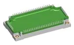
Converter - Brake - Inverter Module (CBI3)
21 D11 1 D12 D13 2 D14 D15 7 3 D16 14 23 24 8 NTC T7 22 D7 T1 16 15 6 T2 11 10 D2 12 D1 T3 18 17 T4 D3 T5 20 19 T6 13 D5
5 D4
4 D6
B4
9
Three Phase Rectifier VRRM = 1600 V IFAVM = 42 A IFSM = 300 A
Brake Chopper VCES = 1200 V IC25 = 35 A VCE(sat) = 2.3 V
Three Phase Inverter VCES = 1200 V IC25 = 50 A VCE(sat) = 2.5 V
Application: AC motor drives with
q
Input Rectifier D11 - D16 Symbol VRRM IFAV IDAVM IFSM Ptot TC = 80°C; sine 180° TC = 80°C; rectangular; d = 1/3; bridge TVJ = 25°C; t = 10 ms; sine 50 Hz TC = 25°C Conditions Maximum Ratings 1600 30 80 300 100 V A A A W
q
q
Input from single or three phase grid Three phase synchronous or asynchronous motor electric braking operation
Features
q
q
Symbol
Conditions
Characteristic Values (TVJ = 25°C, unless otherwise specified) min. typ. max. 1.2 1.2 0.4 1.4 0.02 V V mA mA
q
q
VF IR RthJC
IF = 35 A; TVJ = 25°C TVJ = 125°C VR = VRRM; TVJ = 25°C TVJ = 125°C (per diode)
q
High level of integration - only one power semiconductor module required for the whole drive NPT IGBT technology with low saturation voltage, low switching losses, high RBSOA and short circuit ruggedness Epitaxial free wheeling diodes with Hiperfast and soft reverse recovery Industry standard package with insulated copper base plate and soldering pins for PCB mounting Temperature sense included
1.3 K/W
IXYS reserves the right to change limits, test conditions and dimensions.
Revision A 07.03.2001
© 2001 IXYS All rights reserved
1-4
110
�MUBW 35-12 A8
Output Inverter T1 - T6 Symbol VCES VGES IC25 IC80 RBSOA tSC (SCSOA) Ptot Conditions TVJ = 25°C to 150°C Continuous TC = 25°C TC = 80°C VGE = ±15 V; RG = 47 Ω; TVJ = 125°C Clamped inductive load; L = 100 µH VCE = VCES; VGE = ±15 V; RG = 47 Ω; TVJ = 125°C non-repetitive TC = 25°C Maximum Ratings 1200 ± 20 50 35 ICM = 50 VCEK ≤ VCES 10 225 V V A A A µs W
B4
Symbol Conditions Characteristic Values (TVJ = 25°C, unless otherwise specified) min. typ. max. 2.5 2.9 4.5 1.0 200 100 70 500 70 5.3 3.9 1.65 120 3.1 6.5 1.1 V V V mA mA nA ns ns ns ns mJ mJ nF nC 0.55 K/W
VCE(sat) VGE(th) ICES IGES td(on) tr td(off) tf Eon Eoff Cies QGon RthJC
IC = 35 A; VGE = 15 V; TVJ = 25°C TVJ = 125°C IC = 1 mA; VGE = VCE VCE = VCES; VGE = 0 V; TVJ = 25°C TVJ = 125°C VCE = 0 V; VGE = ± 20 V Inductive load, TVJ = 125°C VCE = 600 V; IC = 35 A VGE = ±15 V; RG = 47 Ω
VCE = 25 V; VGE = 0 V; f = 1 MHz VCE= 600 V; VGE = 15 V; IC = 35 A (per IGBT)
Output Inverter D1 - D6 Symbol IF25 IF80 Conditions TC = 25°C TC = 80°C Maximum Ratings 50 35 A A
Symbol VF IRM trr RthJC
Conditions IF = 35 A; VGE = 0 V; TVJ = 25°C TVJ = 125°C IF = 30 A; diF/dt = -500 A/µs; TVJ = 125°C VR = 600 V; VGE = 0 V (per diode)
Characteristic Values min. typ. max. 2.4 1.8 27 150 2.8 V V A ns 1.19 K/W
© 2001 IXYS All rights reserved
2-4
�MUBW 35-12 A8
Brake Chopper T7 Symbol VCES VGES IC25 IC80 RBSOA tSC (SCSOA) Ptot Symbol Conditions TVJ = 25°C to 150°C Continuous TC = 25°C TC = 80°C VGE = ±15 V; RG = 82 Ω; TVJ = 125°C Clamped inductive load; L = 100 µH VCE = VCES; VGE = ±15 V; RG = 82 Ω; TVJ = 125°C non-repetitive TC = 25°C Conditions Maximum Ratings 1200 ± 20 35 25 ICM = 35 VCEK ≤ VCES 10 180 V V A A A µs W
Characteristic Values (TVJ = 25°C, unless otherwise specified) min. typ. max. 2.3 2.6 4.5 0.8 200 100 75 500 70 3.1 2.4 1 70 3.0 6.5 0.8 V V V mA mA nA ns ns ns ns mJ mJ nF nC 0.7 K/W
B4
VCE(sat) VGE(th) ICES IGES td(on) tr td(off) tf Eon Eoff Cies QGon RthJC
IC = 20 A; VGE = 15 V; TVJ = 25°C TVJ = 125°C IC = 0.6 mA; VGE = VCE VCE = VCES; VGE = 0 V; TVJ = 25°C TVJ = 125°C VCE = 0 V; VGE = ± 20 V
Inductive load, TVJ = 125°C VCE = 600 V; IC = 20 A VGE = ±15 V; RG = 82 Ω
VCE = 25 V; VGE = 0 V; f = 1 MH z VCE= 600 V; VGE = 15 V; IC = 20 A
Brake Chopper D7 Symbol VRRM IF25 IF80 Symbol VF IR IRM trr RthJC © 2001 IXYS All rights reserved Conditions TVJ = 25°C to 150°C TC = 25°C TC = 80°C Conditions IF = 20 A; TVJ = 25°C TVJ = 125°C VR = VRRM; TVJ = 25°C TVJ = 125°C IF = 10 A; diF/dt = -400 A/µs; TVJ = 125°C VR = 600 V Maximum Ratings 1200 16 11 V A A
Characteristic Values min. typ. max. 3.2 2.5 0.07 13 110 3.6 0.06 V V mA mA A ns 3.2 K/W
3-4
�MUBW 35-12 A8
Temperature Sensor NTC Symbol R25 B25/50 Module Symbol TVJ TJM Tstg VISOL Md Symbol Rpin-chip dS dA RthCH Weight Dimensions in mm (1 mm = 0.0394") Creepage distance on surface Strike distance in air with heatsink compound 6 6 0.01 300 IISOL ≤ 1 mA; 50/60 Hz Mounting torque (M5) Conditions Conditions Maximum Ratings -40...+150 150 -40...+125 2500 3-6 °C °C °C V~ Nm Conditions T = 25°C Characteristic Values min. typ. max. 4.75 5.0 3375 5.25 kΩ K
B4
Characteristic Values min. typ. max. 5 mΩ mm mm K/W g
© 2001 IXYS All rights reserved
4-4
�
很抱歉,暂时无法提供与“MUBW35-12A8”相匹配的价格&库存,您可以联系我们找货
免费人工找货