### 物料型号
- 型号:MWI 75-12 A8
- 制造商:IXYS
### 器件简介
- 技术:NPT IGBT技术
- 特点:低饱和电压、低开关损耗、开关频率高达30kHz、正方形RBSOA、无锁存、高短路能力、正温度系数便于并联、MOS输入电压控制、超快速自由轮二极管、可焊引脚适用于PCB安装、带铜基板的封装。
### 引脚分配
- IGBT:MOS输入,电压控制
- 自由轮二极管:超快速自由轮二极管
### 参数特性
- 最大额定值:
- VcES:1200V
- VGES:±20V
- Ic25:125A
- Icao:85A
- RBSOA:150A(特定条件下)
- 典型应用条件:
- VCE(sat):2.2V至2.6V
- VGE(th):4.5V至6.5V
- CcS:3mA至5mA
- t_d(on):100ns至650ns
- t_r:50ns至650ns
- E_on:12.1mJ至10.5mJ
### 功能详解
- IGBT模块:用于AC电机控制、AC伺服和机器人驱动、电源供应。
- 自由轮二极管:用于在IGBT关断时提供电流路径,防止电压尖峰。
### 应用信息
- 应用领域:AC电机控制、AC伺服和机器人驱动、电源供应。
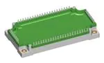
### 封装信息
- 操作温度:-40℃至+125℃
- 存储温度:-40℃至+125℃
- 绝缘电压:2500V
- 安装扭矩:3-6Nm
- 重量:约300g