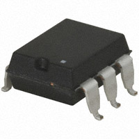
PLA134
100V, 350mA Single-Pole
Normally Open Relay
INTEGRATED CIRCUITS DIVISION
Parameter
Blocking Voltage
Load Current
On-Resistance (max)
Rating
100
350
3
Units
VP
mArms / mADC
Features
•
•
•
•
•
•
•
3750Vrms Input/Output Isolation
Low Drive Power Requirements
Greater Reliability than Electromechanical Relays
No EMI/RFI Generation
Small 6-Pin Package
Surface Mount Tape & Reel Version Available
Flammability Rating UL 94 V-0
Description
The PLA134 is a single-pole, normally open
(1-Form-A) Solid State Relay that uses optically
coupled MOSFET technology to provide 3750Vrms
of input-to-output isolation. With its combination of
low on-resistance and high load current handling,
the PLA134 is suitable for a variety of industrial
applications.
Its optically coupled outputs, which use the patented
OptoMOS architecture, are controlled by a highly
efficient infrared LED.
Because Solid State Relays have no moving parts,
they can offer faster, bounce-free switching in a more
compact surface mount or though hole package than
traditional electromechanical relays.
Applications
•
•
•
•
•
•
•
•
•
Instrumentation
Multiplexers
Data Acquisition
Electronic Switching
I/O Subsystems
Meters (Watt-Hour, Water, Gas)
Medical Equipment—Patient/Equipment Isolation
Security
Industrial Controls
Approvals
• UL Recognized Component: File E76270
• TUV EN 62368-1: Certificate # B 082667 0008
Ordering Information
Part Number
PLA134
PLA134S
PLA134STR
Description
6-Pin DIP (50/Tube)
6-Pin Surface Mount (50/Tube)
6-Pin Surface Mount (1,000/Reel)
Pin Configuration
AC/DC Configuration
+ Control
– Control
N/C
1
6
2
5
3
4
Load
Do Not Use
Load
DC Only Configuration
+ Control
– Control
N/C
1
6
2
5
3
4
+ Load
– Load
Switching Characteristics of
Normally Open Devices
Form-A
IF
90%
10%
ILOAD
ton
DS-PLA134-R07
www.ixysic.com
toff
1
�INTEGRATED CIRCUITS DIVISION
PLA134
Absolute Maximum Ratings @ 25ºC
Parameter
Blocking Voltage
Reverse Input Voltage
Input Control Current
Peak (10ms)
Input Power Dissipation 1
Total Power Dissipation 2
Isolation Voltage, Input to Output
Operational Temperature, Ambient
Storage Temperature
1
Derate linearly 1.33 mW / ºC
2
Derate output power linearly 6.67 mW / ºC
Ratings
100
5
50
1
150
800
3750
-40 to +85
-40 to +125
Units
VP
V
mA
A
mW
mW
Vrms
°C
°C
Absolute Maximum Ratings are stress ratings. Stresses in
excess of these ratings can cause permanent damage to
the device. Functional operation of the device at conditions
beyond those indicated in the operational sections of this
data sheet is not implied.
Typical values are characteristic of the device at +25°C,
and are the result of engineering evaluations. They are
provided for information purposes only, and are not part of
the manufacturing testing requirements.
Electrical Characteristics @ 25ºC
Parameter
Output Characteristics
Blocking Voltage
Load Current
Continuous, AC/DC Configuration
Continuous, DC Configuration
Peak
On-Resistance 1
AC/DC Configuration
DC Configuration
Off-State Leakage Current
Switching Speeds
Turn-On
Turn-Off
Input Characteristics
Input Control Current to Activate
Input Control Current to Deactivate
Input Voltage Drop
Reverse Input Current
Common Characteristics
Capacitance, Input to Output
1
2
Conditions
Symbol
Min
Typ
Max
Units
IL=1A
VDRM
100
-
-
VP
-
IL
t=10ms
ILPK
-
-
350
750
±1
mArms / mADC
mADC
mAP
-
-
3
0.8
1
µA
IF=350mA
IF=750mA
VL=100VP
RON
ILEAK
IF=5mA, IL=10mA
ton
toff
-
-
5
ms
IL=350mA
IF=5mA
VR=5V
IF
IF
VF
IR
0.4
0.9
-
1.36
-
5
1.5
10
mA
mA
V
µA
VIO=0V, f=1MHz
CIO
-
3
-
pF
Measurement taken within one second of on-time.
www.ixysic.com
R07
�INTEGRATED CIRCUITS DIVISION
PLA134
PERFORMANCE DATA*
Typical LED Forward Voltage Drop
(N=50, IF=5mA)
25
Device Count (N)
Device Count (N)
25
20
15
10
5
20
15
10
5
1.364
1.366
1.368
1.370
1.372
LED Forward Voltage Drop (V)
0.9
15
10
5
0.15
0.21
0.27
0.33
Turn-On Time (ms)
0.39
0.065
25
20
20
20
10
5
Device Count (N)
25
Device Count (N)
25
15
15
10
5
0
0
0.75
1.05
1.35
1.65
1.95
LED Current (mA)
0.075
0.085
0.095
Turn-Off Time (ms)
0.105
Typical On-Resistance Distribution
(N=50, IF=5mA, IL=350mADC)
Typical IF for Switch Dropout
(N=50, IL=350mADC)
Typical IF for Switch Operation
(N=50, IL=350mADC)
Device Count (N)
20
0
0
0
Typical Turn-Off Time
(N=50, IF=5mA, IL=350mADC)
25
Device Count (N)
30
Typical Turn-On Time
(N=50, IF=5mA, IL=350mADC)
15
10
5
0
2.25
0.75
1.05
1.35
1.65
1.95
LED Current (mA)
2.25
2.20
2.25
2.30
2.35
2.40
On-Resistance (:)
2.45
Typical Blocking Voltage Distribution
(N=50)
Device Count (N)
25
20
15
10
5
0
100
1.6
IF=10mA
IF=5mA
IF=2mA
1.5
1.4
1.3
1.2
1.1
0.25
Turn-Off Time (ms)
Turn-On Time (ms)
LED Forward Voltage Drop (V)
0.30
1.7
150
Typical Turn-On Time
vs. LED Forward Current
(IL=200mADC)
Typical LED Forward Voltage Drop
vs. Temperature
1.8
110
120
130
140
Blocking Voltage (VP)
0.20
0.15
0.10
0.05
0
1.0
-50
-25
0
25
50
Temperature (ºC)
75
100
0
5
10 15 20 25 30 35 40
LED Forward Current (mA)
45
50
Typical Turn-Off Time
vs. LED Forward Current
(IL=200mADC)
0.20
0.18
0.16
0.14
0.12
0.10
0.08
0.06
0.04
0.02
0
0
5
10 15 20 25 30 35 40
LED Forward Current (mA)
45
50
*Unless otherwise noted, data presented in these graphs is typical of device operation at 25ºC.
R07
www.ixysic.com
3
�INTEGRATED CIRCUITS DIVISION
PLA134
PERFORMANCE DATA*
Typical Turn-Off Time
vs. Temperature
(IF=5mA, IL=200mADC)
Typical Turn-On Time
vs. Temperature
(IF=5mA, IL=200mADC)
0.7
0.11
0.4
0.3
0.2
0.08
0.07
0.06
0.05
0.04
0.03
0
-40
-20
0
20
40
60
Temperature (ºC)
80
0
-40
100
Typical IF for Switch Operation
vs. Temperature
(IL=200mADC)
3.0
20
40
60
Temperature (ºC)
80
1.5
1.0
2.0
1.5
1.0
20
40
60
Temperature (ºC)
80
100
Load Current (mA)
0
-100
-200
-300
20
40
60
Temperature (ºC)
80
20
40
60
Temperature (ºC)
80
100
IF=5mA
2.0
1.5
IF=10mA
1.0
0.5
-40
100
-20
0
20
40
60
Temperature (ºC)
80
100
Maximum Load Current
vs. Temperature
DC Configuration
900
800
400
300
IF=10mA
200
IF=5mA
100
700
600
500
IF=10mA
400
IF=5mA
300
200
100
-1.0
-0.5
0
0.5
Load Voltage (V)
1.0
0
-40
1.5
Typical Blocking Voltage
vs. Temperature
-20
0
20
40
60
80
Temperature (ºC)
100
0.018
150
0.016
Leakage (PA)
100
75
50
20
40
60
Temperature (ºC)
80
100
0.012
0.010
0.008
0.006
0
-40
20
40
60
80
Temperature (ºC)
100
120
10s
100s
2.0
1.6
1.2
0.8
0.4
0.002
0
0
Energy Rating Curve
0.004
25
-20
2.4
0.014
125
-20
0
-40
120
Typical Leakage vs. Temperature
Measured Across Pins 4&6
175
0
-40
0
500
100
-400
-1.5
-20
600
300
0
Typical On-Resistance vs. Temperature
DC-Only Configuration
(IL=350mADC)
Maximum Load Current
vs. Temperature
AC/DC Configuration
Typical Load Current vs. Load Voltage
(IF=5mA)
200
-20
0
-40
Load Current (mA)
0
1
2.5
Load Current (A)
400
-20
IF=5mA Instantaneous
2
-40
0
-40
3
3.0
0.5
0
4
100
On-Resistance (:)
2.0
0.5
Load Current (mA)
0
2.5
LED Current (mA)
LED Current (mA)
2.5
IF=10mA
0
-20
Typical IF for Switch Dropout
vs. Temperature
(IL=200mADC)
3.0
IF=5mA
5
0.09
On-Resistance (:)
Turn-Off Time (ms)
Turn-On Time (ms)
0.5
0.1
Blocking Voltage (VP)
6
0.10
0.6
Typical On-Resistance vs. Temperature
AC/DC Configuration
(IL=350mADC)
-20
0
20
40
60
Temperature (ºC)
80
100
0
10Ps 100Ps 1ms 10ms 100ms
Time
1s
*Unless otherwise noted, data presented in these graphs is typical of device operation at 25ºC.
4
www.ixysic.com
R07
�INTEGRATED CIRCUITS DIVISION
PLA134
Manufacturing Information
Moisture Sensitivity
All plastic encapsulated semiconductor packages are susceptible to moisture ingression. IXYS Integrated
Circuits classifies its plastic encapsulated devices for moisture sensitivity according to the latest version of
the joint industry standard, IPC/JEDEC J-STD-020, in force at the time of product evaluation. We test all of
our products to the maximum conditions set forth in the standard, and guarantee proper operation of our devices
when handled according to the limitations and information in that standard as well as to any limitations set forth in the
information or standards referenced below.
Failure to adhere to the warnings or limitations as established by the listed specifications could result in reduced product
performance, reduction of operable life, and/or reduction of overall reliability.
This product carries a Moisture Sensitivity Level (MSL) classification as shown below, and should be handled
according to the requirements of the latest version of the joint industry standard IPC/JEDEC J-STD-033.
Device
Moisture Sensitivity Level (MSL) Classification
PLA134S
MSL 1
ESD Sensitivity
This product is ESD Sensitive, and should be handled according to the industry standard JESD-625.
Soldering Profile
Provided in the table below is the IPC/JEDEC J-STD-020 Classification Temperature (TC) and the maximum total dwell
time (tP) in all reflow processes that the body temperature of these surface mount devices may be (TC - 5)°C or greater.
The device’s body temperature must not exceed the Classification Temperature at any time during reflow soldering
processes.
Device
Classification Temperature (Tc)
Dwell Time (tP)
Max Reflow Cycles
PLA134S
250ºC
30 seconds
3
For through-hole devices, the maximum pin temperature and maximum dwell time through all solder waves is
provided in the table below. Dwell time is the interval beginning when the pins are initially immersed into the solder
wave until they exit the solder wave. For multiple waves, the dwell time is from entering the first wave until exiting the
last wave. During this time, pin temperatures must not exceed the maximum temperature given in the table below.
Body temperature of the device must not exceed the limit shown in the table below at any time during the soldering
process.
Device
PLA134
Maximum Pin Temperature
260ºC
Maximum Body Temperature
250ºC
Maximum Dwell Time
10 seconds*
Wave Cycles
1
*Total cumulative duration of all waves.
Board Wash
IXYS Integrated Circuits recommends the use of no-clean flux formulations. Board washing to reduce or remove flux
residue following the solder reflow process is acceptable provided proper precautions are taken to prevent damage to
the device. These precautions include but are not limited to: using a low pressure wash and providing a follow up bake
cycle sufficient to remove any moisture trapped within the device due to the washing process. Due to the variability
of the wash parameters used to clean the board, determination of the bake temperature and duration necessary
to remove the moisture trapped within the package is the responsibility of the user (assembler). Cleaning or drying
methods that employ ultrasonic energy may damage the device and should not be used. Additionally, the device must
not be exposed to halide flux or solvents.
R07
www.ixysic.com
5
�INTEGRATED CIRCUITS DIVISION
PLA134
Mechanical Dimensions
PLA134
8.382±0.381
(0.330±0.015)
7.239 TYP
(0.285 TYP)
2.54±0.127
(0.100±0.005)
PCB Hole Pattern
6 - 0.800 DIA.
(6 - 0.031 DIA.)
6.350±0.127
(0.250±0.005)
Pin 1
1.524 TYP
(0.060 TYP)
1.651±0.254
(0.065±0.010)
2.540±0.127
(0.100±0.005)
9.144±0.508
(0.360±0.020)
7.620±0.127
(0.300±0.005)
7.620±0.254
(0.300±0.010)
0.254±0.0127
(0.010±0.0005)
5.080±0.127
(0.200±0.005)
Controlling dimension: inches
3.302±0.051
(0.130±0.002)
4.064 TYP
(0.160 TYP)
Dimensions
mm
(inches)
0.457±0.076
(0.018±0.003)
PLA134S
8.382±0.381
(0.330±0.015)
9.524±0.508
(0.375±0.020)
Pin 1
0.635±0.127
(0.025±0.005)
2.54
(0.10)
6.350±0.127
(0.250±0.005)
0.457±0.076
(0.018±0.003)
1.651±0.254
(0.065±0.010)
7.620±0.254
(0.300±0.010)
0.254±0.0127
(0.010±0.0005)
8.90
(0.3503)
1.65
(0.0649)
0.65
(0.0255)
3.302±0.051
(0.130±0.002)
4.445±0.254
(0.175±0.010)
Controlling dimension: inches
1.524 TYP
(0.060 TYP)
1.651±0.254
(0.065±0.010)
6
PCB Land Pattern
2.54±0.127
(0.100±0.005)
Dimensions
mm
(inches)
www.ixysic.com
R07
�INTEGRATED CIRCUITS DIVISION
PLA134
PLA134STR Tape & Reel
330.2 Dia
(13.00 Dia)
P1 = 12.00
(0.472)
Top Cover
Tape Thickness
0.102 Max
(0.004 Max)
W=16.00
(0.63)
B0 = 10.10
(0.398)
K0 = 4.90
(0.19)
K1 = 3.80
(0.15)
A0 = 10.10
(0.398)
User Direction of Feed
Embossed
Carrier
Embossment
Dimensions
mm
(inches)
NOTES:
1. All dimensions carry tolerances of EIA Standard 481-2
2. The tape complies with all “Notes” for constant dimensions listed on page 5 of EIA-481-2
For additional information please visit our website at: https://www.ixysic.com
Disclaimer Notice - Information furnished is believed to be accurate and reliable. However, users should independently evaluate the suitability of and
test each product selected for their own applications. Littelfuse products are not designed for, and may not be used in, all applications.
Read complete Disclaimer Notice at https://www.littelfuse.com/disclaimer-electronics.
7
Specification: DS-PLA134-R07
©Copyright 2021, Littelfuse, Inc.
OptoMOS® is a registered trademark of IXYS Integrated Circuits
All rights reserved. Printed in USA.
11/4/2021
�