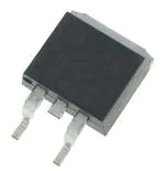
DSEI 19-06AS
VRRM = 600 V
IFAVM = 20 A
trr
= 35 ns
Fast Recovery
Epitaxial Diode (FRED)
VRSM
VRRM
V
V
600
600
A
Type
C
TO-263 AA
NC
A
DSEI 19-06AS
C (TAB)
A = Anode, C = Cathode,
NC = No connection, TAB = Cathode
Symbol
Conditions
IFRMS
IFAVM ①
IFRM
TVJ = TVJM
TC = 65°C; rectangular, d = 0.5
tP < 10 µs; rep. rating, pulse width limited by TVJM
25
20
150
A
A
A
IFSM
TVJ = 45°C; t = 10 ms
t = 8.3 ms
(50 Hz), sine
(60 Hz), sine
100
110
A
A
TVJ = 150°C; t = 10 ms
t = 8.3 ms
(50 Hz), sine
(60 Hz), sine
85
95
A
A
TVJ = 45°C t = 10 ms
t = 8.3 ms
(50 Hz), sine
(60 Hz), sine
50
50
A2s
A2s
TVJ = 150°C; t = 10 ms
t = 8.3 ms
(50 Hz), sine
(60 Hz), sine
36
37
A2s
A2s
-40...+150
150
-40...+150
°C
°C
°C
61
W
2
g
TVJ
TVJM
Tstg
Ptot
TC = 25°C
Weight
Symbol
Conditions
Features
●
●
●
●
●
●
●
International standard surface mount
package JEDEC TO-263 AA
Planar passivated chips
Very short recovery time
Extremely low switching losses
Low IRM-values
Soft recovery behaviour
Epoxy meets UL 94V-0
TO-263 AA Outline
Characteristic Values
typ.
max.
IR
TVJ = 25°C; VR = VRRM
TVJ = 25°C; VR = 0.8 • VRRM
TVJ = 125°C; VR = 0.8 • VRRM
50
25
3
µA
µA
mA
VF
IF = 16 A;
1.5
1.7
V
V
Dim.
VT0
rT
For power-loss calculations only
TVJ = TVJM
1.12
23.2
V
mΩ
Millimeter
Min.
Max.
Inches
Min. Max.
A
A1
4.06
2.03
4.83
2.79
.160
.080
.190
.110
2
K/W
b
b2
0.51
1.14
0.99
1.40
.020
.045
.039
.055
35
50
ns
c
c2
0.46
1.14
0.74
1.40
.018
.045
.029
.055
4
4.4
A
D
D1
8.64
7.11
9.65
8.13
.340
.280
.380
.320
E
E1
e
9.65
6.86
2.54
10.29
8.13
BSC
.380
.270
.100
.405
.320
BSC
L
L1
L2
L3
L4
14.61
2.29
1.02
1.27
0
15.88
2.79
1.40
1.78
0.38
.575
.090
.040
.050
0
.625
.110
.055
.070
.015
R
0.46
0.74
.018
.029
TVJ = 150°C
TVJ= 25°C
RthJC
trr
IF = 1 A; -di/dt = 50 A/µs; VR = 30 V; TVJ = 25°C
IRM
VR = 350 V; IF = 12 A; -diF/dt = 100 A/µs
L ≤ 0.05 µH; TVJ = 100°C
① IFAVM rating includes reverse blocking losses at TVJM, VR = 0.8 VRRM, duty cycle d = 0.5
Data according to IEC 60747
IXYS reserves the right to change limits, test conditions and dimensions
© 2004 IXYS All rights reserved
417
I2t
Maximum Ratings
1-2
�DSEI 19-06AS
Fig. 1 Forward current
versus voltage drop.
Fig. 2 Recovery charge versus -diF/dt.
Fig. 3 Peak reverse current versus
-diF/dt.
Fig. 4 Dynamic parameters versus
junction temperature.
Fig. 5 Recovery time versus -diF/dt.
Fig. 6 Peak forward voltage
versus diF/dt.
IXYS reserves the right to change limits, test conditions and dimensions
2-2
417
Fig. 7 Transient thermal impedance junction to case.
© 2004 IXYS All rights reserved
�Mouser Electronics
Authorized Distributor
Click to View Pricing, Inventory, Delivery & Lifecycle Information:
IXYS:
DSEI19-06AS DSEI19-06AS-TUB DSEI19-06AS-TRL
�
很抱歉,暂时无法提供与“DSEI19-06AS”相匹配的价格&库存,您可以联系我们找货
免费人工找货