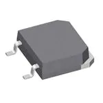
DSP 25
VRRM = 1200/1600 V
IF(RMS) = 2x43 A
IF(AV)M = 2x28 A
Phase-leg
Rectifier Diode
VRSM
VRRM
V
V
1300
1700
1200
1600
TO-247 AD
TO-268 AA
ISOPLUS 247 TM
DSP 25-12AT
DSP 25-16AT
DSP 25-16AR
TO-268 AA
Version A
Version AT
Type
DSP 25-12A
DSP 25-16A
Symbol
Test Conditions
IF(RMS)
IF(AV)M
TVJ = TVJM
Tcase = 100°C; 180° sine
IFSM
TVJ = 45°C;
I2t
TO-247 AD
1
2
3
Maximum Ratings
43
28
A
A
t = 10 ms
t = 8.3 ms
(50 Hz), sine
(60 Hz), sine
300
330
A
A
TVJ = 150°C; t = 10 ms
t = 8.3 ms
(50 Hz), sine
(60 Hz), sine
270
300
A
A
TVJ = 45°C
t = 10 ms
t = 8.3 ms
(50 Hz), sine
(60 Hz), sine
450
450
A2s
A2s
TVJ = 150°C; t = 10 ms
t = 8.3 ms
(50 Hz), sine
(60 Hz), sine
340
325
A2s
A2s
-40...+180
180
-40...+150
°C
°C
°C
0.8...1.2
20...120
Nm
N
TVJ
TVJM
Tstg
Md *
FC
mounting torque M3
mounting force with clip
VISOL **
50/60 Hz, RMS, t = 1 minute, leads-to-tab
Weight
2500
TO-268 / TO-247
4/6
1
2
3
1
2 (TAB)
3
2 (TAB)
ISOPLUS 247 TM
Version AR
1
2
TAB
3
1 = Cathode, 2 = Anode/Cathode, 3 = Anode
Features
●
International standard packages
JEDEC TO-247 AD and TO-268 AA
surface mountable
●
For single and three phase bridge
configuration
●
Planar passivated chips
●
Epoxy meets UL 94V-0 flammability
classification
●
Version AR isolated and
UL registered E153432
V~
g
TO-247 AD and ISOPLUS 247 TM
* Verson A only; ** Version AR only
Test Conditions
IR
TVJ = 150°C
VF
IF = 55 A; TVJ = 25°C
VT0
rT
Characteristic Values
≤
2
mA
≤
1.6
V
For power-loss calculations only
TVJ = TVJM
0.8
15
V
mΩ
RthJC
RthCH
DC current
DC current (with heatsink compound)
1.5
0.4
K/W
K/W
a
Maximum allowable acceleration
100
m/s2
VR = VRRM
Dim.
TO-268 AA Outline
Dim.
Millimeter
Min.
Max.
A
A1
A2
4.9
2.7
.02
5.1
2.9
.25
.193
.106
.001
.201
.114
.010
b
b2
C
1.15
1.9
.4
1.45
2.1
.65
.045
.75
.016
.057
.83
.026
D
E
E1
13.80
15.85
13.3
14.00
16.05
13.6
.543
.624
.524
.551
.632
.535
e
H
L
5.45 BSC
18.70
19.10
2.40
2.70
.215 BSC
.736
.752
.094
.106
L1
L2
L3
L4
1.20
1.40
1.00
1.15
0.25 BSC
3.80
4.10
.047
.055
.039
.045
.010 BSC
.150
.161
Data according to IEC 60747 and refer to a single diode
IXYS reserves the right to change limits, test conditions and dimensions
© 2002 IXYS All rights reserved
Inches
Min.
Max.
Millimeter
Min. Max.
Inches
Min.
Max.
A
B
19.81 20.32
20.80 21.46
0.780
0.819
0.800
0.845
C
D*
15.75 16.26
3.55 3.65
0.610
0.140
0.640
0.144
E
F
4.32
5.4
5.49
6.2
0.170
0.212
0.216
0.244
G
H
1.65
-
2.13
4.5
0.065
-
0.084
0.177
J
K
1.0
10.8
1.4
11.0
0.040
0.426
0.055
0.433
L
M
4.7
0.4
5.3
0.8
0.185
0.016
0.209
0.031
N
1.5
2.49
0.087
0.102
* ISOPLUS 247
TM
without hole
211
Symbol
1-2
�DSP 25
70
A
200
103
50 Hz, 80% VRRM
60
2
It
IFSM
IF 50
VR = 0 V
A2s
A
TVJ = 45°C
40
TVJ = 45°C
100
30
TVJ = 150°C
TVJ = 25°C
20
TVJ = 150°C
TVJ = 150°C
10
0
0.0
0.5
102
0
0.001
1.5 V 2.0
1.0
0.01
0.1
VF
1
s
1
2
3
t
Fig. 1 Forward current versus voltage
drop per diode
4 5 6 7 ms
8 910
t
Fig. 3 I2t versus time per diode
Fig. 2 Surge overload current
60
30
W
A
RthJA:
50
0.5
1.8
3
5
8
15
Ptot
40
30
Id(AV)M
KW
KW
KW
KW
KW
KW
20
20
10
10
0
0
0
5
10
15
20
25 A
0
40
80
120
160 °C
0
Tamb
Id(AV)M
Fig. 4 Power dissipation versus direct output current and ambient temperature, sine 180°
1.6
K/W
1.4
30
60
90 120 150 180°C
TC
Fig. 5 Max. forward current versus
case temperature
1.2
1.0
0.8
Constants for ZthJC calculation:
0.6
i
Rthi (K/W)
ti (s)
0.4
1
2
3
4
5
0.06075
0.183
0.3405
0.543
0.3728
0.0004
0.00256
0.0045
0.0242
0.15
0.2
0.0
0.0001
DSP25
0.001
0.01
0.1
1
s
10
t
Fig. 6 Transient thermal impedance junction to case
© 2002 IXYS All rights reserved
2-2
�
很抱歉,暂时无法提供与“DSP25-16AT”相匹配的价格&库存,您可以联系我们找货
免费人工找货