0
登录后你可以
  • 下载海量资料
  • 学习在线课程
  • 观看技术视频
  • 写文章/发帖/加入社区
会员中心
创作中心
发布
  • 发文章

  • 发资料

  • 发帖

  • 提问

  • 发视频

创作活动
GUO40-12NO1

GUO40-12NO1

  • 厂商:

    IXYS(艾赛斯)

  • 封装:

    SIP-5

  • 描述:

    3-PHASE BRIDGE RECT 1200V 40A

  • 详情介绍
  • 数据手册
  • 价格&库存
GUO40-12NO1 数据手册
GUO40-12NO1 3~ Rectifier Standard Rectifier VRRM = 1200 V I DAV = 40 A I FSM = 370 A 3~ Rectifier Bridge Part number GUO40-12NO1 Backside: isolated + D1 D3 D5 D2 D4 D6 ~ ~ ~ - Features / Advantages: Applications: Package: GUFP ● Low forward voltage drop ● Planar passivated chips ● Easy to mount with one screw ● Space and weight savings ● Supplies for DC power equipment ● Input rectifiers for PWM inverter ● Battery DC power supplies ● Field supply for DC motors ● Isolation Voltage: 2500 V~ ● Industry standard outline ● RoHS compliant ● Epoxy meets UL 94V-0 ● Soldering pins for PCB mounting ● Base plate: Plastic overmolded tab ● Reduced weight Disclaimer Notice Information furnished is believed to be accurate and reliable. However, users should independently evaluate the suitability of and test each product selected for their own applications. Littelfuse products are not designed for, and may not be used in, all applications. Read complete Disclaimer Notice at www.littelfuse.com/disclaimer-electronics. IXYS reserves the right to change limits, conditions and dimensions. © 2019 IXYS all rights reserved Data according to IEC 60747and per semiconductor unless otherwise specified 20191219d GUO40-12NO1 Ratings Rectifier Conditions Symbol VRSM Definition max. non-repetitive reverse blocking voltage TVJ = 25°C VRRM max. repetitive reverse blocking voltage TVJ = 25°C IR reverse current VF forward voltage drop bridge output current VF0 threshold voltage rF slope resistance R thJC thermal resistance junction to case thermal resistance case to heatsink total power dissipation I FSM max. forward surge current I²t CJ value for fusing junction capacitance IXYS reserves the right to change limits, conditions and dimensions. © 2019 IXYS all rights reserved 1200 V TVJ = 25°C 40 µA TVJ = 150°C 1.5 mA TVJ = 25°C 1.06 V 1.28 V 0.92 V IF = 10 A IF = 30 A IF = 10 A IF = 30 A TVJ = 150 °C 1.23 V T VJ = 175 °C 40 A TVJ = 175 °C 0.74 V 16.3 mΩ d=⅓ for power loss calculation only R thCH max. Unit 1300 V VR = 1200 V rectangular Ptot typ. VR = 1200 V TC = 90 °C I DAV min. 4.3 K/W K/W 0.5 TC = 25°C 35 W t = 10 ms; (50 Hz), sine TVJ = 45°C 370 A t = 8,3 ms; (60 Hz), sine VR = 0 V 400 A t = 10 ms; (50 Hz), sine TVJ = 150 °C 315 A t = 8,3 ms; (60 Hz), sine VR = 0 V 340 A t = 10 ms; (50 Hz), sine TVJ = 45°C 685 A²s t = 8,3 ms; (60 Hz), sine VR = 0 V 665 A²s t = 10 ms; (50 Hz), sine TVJ = 150 °C 495 A²s 480 A²s t = 8,3 ms; (60 Hz), sine VR = 0 V VR = 400 V; f = 1 MHz TVJ = 25°C 10 Data according to IEC 60747and per semiconductor unless otherwise specified pF 20191219d GUO40-12NO1 Package Ratings GUFP Symbol I RMS Definition Conditions RMS current per terminal min. TVJ virtual junction temperature T op operation temperature Tstg storage temperature -40 max. 70 Unit A -40 175 °C -40 150 °C 150 °C 8.5 Weight MD mounting torque FC mounting force with clip d Spp/App creepage distance on surface | striking distance through air d Spb/Apb VISOL t = 1 minute 6.7 10.0 50/60 Hz, RMS; IISOL ≤ 1 mA 1.2 Nm 20 120 N 5.4 mm 8.0 mm 2500 V 2100 V Similar Part DNA40U2200GU DMA40U1800GU GUO40-16NO1 GUO40-08NO1 Equivalent Circuits for Simulation V0 50 Ordering Number GUO40-12NO1 R0 Marking on Product GUO40-12NO1 Package GUFP GUFP GUFP GUFP * on die level Delivery Mode Tube Quantity 14 K/W Code No. 514892 Voltage class 2200 1800 1600 800 T VJ = 175°C Rectifier V 0 max threshold voltage 0.74 V R0 max slope resistance * 13.7 mΩ IXYS reserves the right to change limits, conditions and dimensions. © 2019 IXYS all rights reserved g 0.8 thermal resistance junction to ambient Ordering Standard I terminal to terminal terminal to backside t = 1 second isolation voltage RthJA typ. Data according to IEC 60747and per semiconductor unless otherwise specified 20191219d GUO40-12NO1 Outlines GUFP Dim. Z1 O Z2 Q A2 D ØP S1 L 5x b2 5x b C A3 e 4x e A4 E A5 F A6 A X2 X1 Y2 + S2 ~ Y1 ~ ~ R _ L1 +1 +2 A A2 A3 A4 A5 A6 b b2 C D E e F L L1 O ØP Q Ø /2 R s1 s2 t1 t2 x1 x2 y1 y2 z1 Millimeter min typ. max 5.40 5.50 5.60 3.90 4.00 4.10 0.95 1.00 1.10 0.95 1.00 1.05 1.60 1.70 1.80 1.25 1.30 1.35 0.95 1.00 1.05 1.95 2.00 2.05 0.45 0.50 0.55 24.80 25.00 25.20 34.70 35.00 35.30 BSC 7.50 2.40 2.50 2.60 20.30 20.40 20.50 3.70 3.75 3.80 17.40 17.50 17.60 4.10 4.20 4.30 9.20 9.30 9.40 1.77 3.45 3.50 3.55 1.45 1.50 1.55 0.95 1.00 1.05 0.95 1.00 1.05 3.20 3.30 3.40 1.90 1.60 4.65 2.80 2.00 1.65 4.70 2.90 2.10 1.70 4.75 3.00 min 0.213 0.154 0.037 0.037 0.063 0.049 0.037 0.077 0.018 0.977 1.367 BSC 0.095 0.800 0.146 0.686 0.162 0.362 0.136 0.057 0.037 0.037 0.126 0.075 0.063 0.183 0.110 Inches typ. 0.217 0.158 0.039 0.039 0.067 0.051 0.039 0.079 0.020 0.985 1.379 0.296 0.099 0.804 0.148 0.690 0.165 0.366 0.070 0.138 0.059 0.039 0.039 0.130 0.079 0.065 0.185 0.114 max 0.221 0.162 0.043 0.041 0.071 0.053 0.041 0.081 0.022 0.993 1.391 0.102 0.808 0.150 0.693 0.169 0.370 0.140 0.061 0.041 0.041 0.134 0.083 0.067 0.187 0.118 + D1 D3 D5 D2 D4 D6 ~ ~ ~ - IXYS reserves the right to change limits, conditions and dimensions. © 2019 IXYS all rights reserved Data according to IEC 60747and per semiconductor unless otherwise specified 20191219d GUO40-12NO1 Rectifier 60 300 40 250 800 50 Hz 0.8 x V RRM VR = 0 V 600 IF TVJ = 45°C IFSM I 2t TVJ = 45°C 400 [A] [A] 2 [A s] 200 20 0 0.4 0.8 1.2 150 10-3 1.6 10-2 10-1 1 Fig. 1 Forward current vs. voltage drop per diode Fig. 2 Surge overload current vs. time per diode 2 Fig. 3 I t vs. time per diode 40 RthJA: DC = 1 0.5 0.4 0.33 0.17 0.08 10 t [ms] t [s] 12 0 100 VF [V] 16 [W] 200 TVJ = 25°C 20 Ptot TVJ = 150°C TVJ = 150°C TVJ = 125°C 150°C DC = 0.6 KW 1 0.8 KW 1 KW 2 KW 4 KW 8 KW 30 0.5 0.4 0.33 IF(AV)M 0.17 20 0.08 [A] 8 10 4 0 0 0 4 8 12 16 0 25 50 IF(AV)M [A] 75 100 125 150 175 0 25 50 75 100 125 150 175 TC [°C] TA [°C] Fig. 4 Power dissipation vs. forward current and ambient temperature per diode Fig. 5 Max. forward current vs. case temperature per diode 5 4 ZthJC 3 Constants for ZthJC calculation: [K/W] i Rth (K/W) ti (s) 1 0.302 0.002 2 1.252 0.032 3 1.582 0.227 4 1.164 0.820 2 1 0 1 10 100 1000 10000 t [ms] Fig. 6 Transient thermal impedance junction to case vs. time per diode IXYS reserves the right to change limits, conditions and dimensions. © 2019 IXYS all rights reserved Data according to IEC 60747and per semiconductor unless otherwise specified 20191219d
GUO40-12NO1
物料型号:GUO40-12NO1

器件简介:这是一个标准整流器,具有低正向电压降、平面钝化芯片、易于用一个螺丝安装等特点,有助于节省空间和重量。

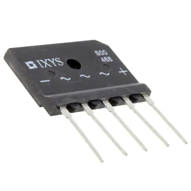
引脚分配:PDF中提供了整流器的引脚分配图,其中D1和D3为一个桥式整流器的输入端,D2、D4和D6为输出端。

参数特性: - 最大非重复反向阻断电压(VRSM):1300V - 最大重复反向阻断电压(VRRM):1200V - 反向电流(R):在25°C时小于40uA,150°C时小于1.5mA - 正向电压降(VE):在10A电流下为1.06V,30A时为1.28V - 桥式整流器输出电流(IDAV):40A - 最大正向浪涌电流(FSM):370A(10ms, 50Hz正弦波)

功能详解: - 该整流器适用于直流电源设备、PWM逆变器的输入整流器、电池直流电源和直流电机的现场供电。

应用信息: - 整流器适用于多种应用,包括直流电源设备、PWM逆变器的输入整流器、电池直流电源和直流电机的现场供电。

封装信息: - 封装类型:GUFP - 隔离电压:2500V - 符合行业标准外形尺寸 - 符合RoHS标准 - 环氧树脂符合UL 94V-0标准 - 用于PCB安装的焊接引脚 - 基板:塑料覆盖成型标签 - 减少重量
GUO40-12NO1 价格&库存

很抱歉,暂时无法提供与“GUO40-12NO1”相匹配的价格&库存,您可以联系我们找货

免费人工找货
GUO40-12NO1
  •  国内价格 香港价格
  • 1+117.815651+13.91903
  • 14+92.6791314+10.94934

库存:6117

GUO40-12NO1
    •  国内价格
    • 1+351.21915
    • 2+332.35571

    库存:117