Advance Technical Information
IXGK55N120A3H1
IXGX55N120A3H1
GenX3TM 1200V
IGBTs w/ Diode
VCES = 1200V
IC110 = 55A
VCE(sat) ≤ 2.3V
Ultra-Low-Vsat PT IGBTs for
up to 3kHz Switching
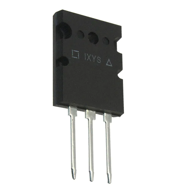
TO-264 (IXGK)
Symbol
Test Conditions
Maximum Ratings
VCES
TJ = 25°C to 150°C
1200
V
VCGR
TJ = 25°C to 150°C, RGE = 1MΩ
1200
V
VGES
Continuous
±20
V
VGEM
Transient
±30
V
IC25
IC110
ILRMS
ICM
TC
TC
TC
TC
125
55
120
400
A
A
A
A
SSOA
(RBSOA)
VGE = 15V, TVJ = 125°C, RG = 3Ω
Clamped Inductive Load
ICM = 110
@ 0.8 • VCES
A
PC
TC = 25°C
460
W
-55 ... +150
°C
= 25°C ( Chip Capability )
= 110°C
= 25°C (Lead RMS Limit)
= 25°C, 1ms
TJ
TJM
150
°C
Tstg
-55 ... +150
°C
300
260
°C
°C
1.13/10
20..120/4.5..27
Nm/lb.in.
N/lb.
10
6
g
g
TL
TSOLD
Maximum Lead Temperature for Soldering
1.6 mm (0.062 in.) from Case for 10
Md
FC
Mounting Torque ( IXGK )
Mounting Force ( IXGX )
Weight
TO-264
PLUS247
G
G
VGE(th)
IC
= 1mA, VCE = VGE
ICES
VCE = VCES, VGE = 0V
3.0
5.0
IGES
VCE = 0V, VGE = ±20V
VCE(sat)
IC
= IC110, VGE = 15V, Note 2
TJ = 125°C
±100 nA
1.85
1.90
2.3
E
Tab
E
= Emitter
Tab = Collector
Features
z
z
Optimized for Low Conduction Losses
Anti-Parallel Ultra Fast Diode
Advantages
V
z
z
z
z
z
z
z
z
z
© 2010 IXYS CORPORATION, All Rights Reserved
Tab
High Power Density
Low Gate Drive Requirement
Applications
V
100 μA
2.0 mA
Note 1, TJ = 125°C
C
G = Gate
C = Collector
z
Characteristic Values
Min.
Typ.
Max.
E
E
PLUS247TM (IXGX)
z
Symbol
Test Conditions
(TJ = 25°C, Unless Otherwise Specified)
C
Power Inverters
UPS
Motor Drives
SMPS
PFC Circuits
Battery Chargers
Welding Machines
Lamp Ballasts
Inrush Current Protection Circuits
DS100227(01/10)
�IXGK55N120A3H1
IXGX55N120A3H1
Symbol
Test Conditions
(TJ = 25°C, Unless Otherwise Specified)
Characteristic Values
Min.
Typ.
Max.
gfs
30
IC = IC110, VCE = 10V, Note 2
Cies
Coes
TO-264 (IXGK) Outline
45
S
4340
pF
300
pF
VCE = 25V, VGE = 0V, f = 1 MHz
Cres
115
pF
Qg(on)
185
nC
Qge
IC = IC110, VGE = 15V, VCE = 0.5 • VCES
Qgc
td(on)
tri
Inductive load, TJ = 25°C
25
nC
75
nC
23
ns
42
ns
Eon
IC
= IC110, VGE = 15V
5.1
mJ
td(off)
VCE = 0.8 • VCES, RG = 3Ω
365
ns
tfi
Note 3
282
ns
Eoff
13.3
mJ
td(on)
24
ns
tri
Inductive load, TJ = 125°C
46
ns
Eon
IC = IC110, VGE = 15V
9.5
mJ
td(off)
VCE = 0.8 • VCES, RG = 3Ω
tfi
Eoff
Note 3
618
ns
635
ns
29.0
mJ
Terminals:
1 = Gate
2 = Collector
3 = Emitter
0.27 °C/W
RthJC
RthCK
0.15
°C/W
PLUS 247TM (IXGX) Outline
Reverse Diode (FRED)
Symbol
Test Conditions
(TJ = 25°C, Unless Otherwise Specified)
Characteristic Values
Min.
Typ.
Max.
VF
IF = 60A, VGE = 0V, Note 2
trr
IF = 60A, VGE = 0V,
200
ns
IRM
-diF/dt = 350A/μs, VR = 600V, TJ = 100°C
24.6
A
1.85
1.90
TJ = 150°C
RthJC
2.5
V
V
0.42 °C/W
Notes:
1. Part must be heatsunk for high-temp Ices measurement.
2. Pulse test, t ≤ 300μs, duty cycle, d ≤ 2%.
3. Switching times & energy losses may increase for higher VCE(Clamp), TJ or RG.
ADVANCE TECHNICAL INFORMATION
The product presented herein is under development. The Technical Specifications offered are derived
from a subjective evaluation of the design, based upon prior knowledge and experience, and constitute a
"considered reflection" of the anticipated result. IXYS reserves the right to change limits, test
conditions, and dimensions without notice.
Terminals:
Dim.
A
A1
A2
b
b1
b2
C
D
E
e
L
L1
Q
R
1 = Gate
2 = Collector
3 = Emitter
Millimeter
Min. Max.
4.83
5.21
2.29
2.54
1.91
2.16
1.14
1.40
1.91
2.13
2.92
3.12
0.61
0.80
20.80 21.34
15.75 16.13
5.45 BSC
19.81 20.32
3.81
4.32
5.59
6.20
4.32
4.83
Inches
Min. Max.
.190 .205
.090 .100
.075 .085
.045 .055
.075 .084
.115 .123
.024 .031
.819 .840
.620 .635
.215 BSC
.780 .800
.150 .170
.220 0.244
.170 .190
IXYS Reserves the Right to Change Limits, Test Conditions, and Dimensions.
IXYS MOSFETs and IGBTs are covered
4,835,592
by one or more of the following U.S. patents: 4,850,072
4,881,106
4,931,844
5,017,508
5,034,796
5,049,961
5,063,307
5,187,117
5,237,481
5,381,025
5,486,715
6,162,665
6,259,123 B1
6,306,728 B1
6,404,065 B1
6,534,343
6,583,505
6,683,344
6,727,585
7,005,734 B2
6,710,405 B2 6,759,692
7,063,975 B2
6,710,463
6,771,478 B2 7,071,537
7,157,338B2
�Disclaimer Notice - Information furnished is believed to be accurate and reliable. However, users should independently
evaluate the suitability of and test each product selected for their own applications. Littelfuse products are not designed for,
and may not be used in, all applications. Read complete Disclaimer Notice at www.littelfuse.com/disclaimer-electronics.
�


 工商网监
湘ICP备2023018690号
工商网监
湘ICP备2023018690号
