Preliminary Technical Information
High-Gain IGBT
w/ Diode
IXGP30N60B4D1
VCES =
IC110 =
VCE(sat)
tfi(typ) =
High-Speed PT Trench IGBT
600V
30A
1.7V
88ns
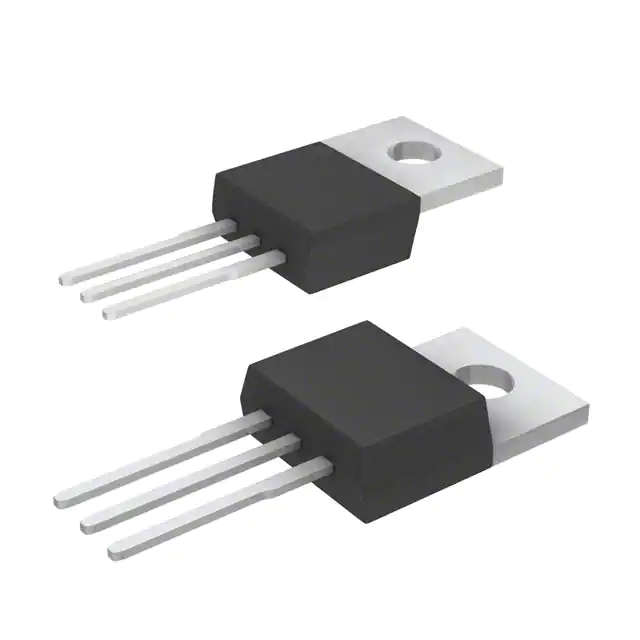
TO-220
Symbol
Test Conditions
Maximum Ratings
VCES
VCGR
TJ = 25°C to 150°C
TJ = 25°C to 150°C, RGE = 1M
600
600
V
V
VGES
VGEM
Continuous
Transient
±20
±30
V
V
IC25
IC110
IF110
ICM
TC
TC
TC
TC
56
30
10
156
A
A
A
A
SSOA
(RBSOA)
VGE = 15V, TVJ = 125°C, RG = 10
Clamped Inductive Load
ICM = 48
VCE VCES
A
PC
TC = 25°C
190
W
-55 ... +150
150
-55 ... +150
°C
°C
°C
300
260
°C
°C
1.13/10
Nm/lb.in.
3
g
= 25°C
= 110°C
= 110°C
= 25°C, 1ms
TJ
TJM
Tstg
TL
TSOLD
Maximum Lead Temperature for Soldering
1.6 mm (0.062in.) from Case for 10s
Md
Mounting Torque
Weight
G
CE
G = Gate
E = Emitter
Tab
C = Collector
Tab = Collector
Features
Optimized for Low Conduction and
Switching Losses
Square RBSOA
Anti-Parallel Ultra Fast Diode
International Standard Package
Advantages
High Power Density
Low Gate Drive Requirement
Applications
• Switch-Mode and Resonant-Mode
Symbol
Test Conditions
(TJ = 25C, Unless Otherwise Specified)
Characteristic Values
Min.
Typ.
Max.
VGE(th)
IC
3.0
ICES
VCE = VCES, VGE= 0V
= 250A, VCE = VGE
5.5
V
10
500
A
A
100
nA
TJ = 125C
IGES
VCE = 0V, VGE = 20V
VCE(sat)
IC
= 24A, VGE = 15V, Note 1
TJ = 125C
© 2013 IXYS CORPORATION, All Rights Reserved
Power Supplies
1.5
1.5
1.7
• Uninterruptible Power Supplies (UPS)
• DC Choppers
• AC Motor Speed Drives
• DC Servo and Robot Drives
PFC Circuits
V
V
DS100275B(8/13)
�IXGP30N60B4D1
Symbol Test Conditions
(TJ = 25°C Unless Otherwise Specified)
Characteristic Values
Min.
Typ.
Max.
gfs
IC = 24A, VCE = 10V, Note 1
10
Cies
Coes
Cres
VCE = 25V, VGE = 0V, f = 1MHz
Qg
Qge
Qgc
td(on)
tri
Eon
td(off)
tfi
Eoff
td(on)
tri
Eon
td(off)
tfi
Eoff
IC = 24A, VGE = 15V, VCE = 0.5 • VCES
Inductive Load, TJ = 25°C
IC = 24A, VGE = 15V
VCE = 400V, RG = 10
Note 2
Inductive Load, TJ = 125°C
IC = 24A, VGE = 15V
VCE = 400V, RG = 10
Note 2
RthJC
RthCS
TO-220 (IXGP) Outline
17
S
860
70
29
pF
pF
pF
77
9
33
nC
nC
nC
21
34
0.44
200
88
0.70
ns
ns
mJ
ns
ns
mJ
1.30
20
33
0.75
288
223
1.50
ns
ns
mJ
ns
ns
mJ
0.50
0.66 °C/W
°C/W
Pins:
1 - Gate
3 - Emitter
2 - Collector
Reverse Diode (FRED)
Symbol
Test Conditions
(TJ = 25C, Unless Otherwise Specified)
Characteristic Values
Min.
Typ.
Max.
VF
IF = 10A, VGE = 0V, Note 1
IRM
IF = 12A, VGE = 0V,
-diF/dt = 100A/μs, VR = 100V, TJ = 125°C
trr
2.66
1.66
TJ = 150°C
IF = 1A, VGE = 0V, -diF/dt = 100A/μs, VR = 30V
trr
2.5
A
110
ns
30
ns
RthJC
Notes:
V
V
2.5 °C/W
1. Pulse test, t 300μs, duty cycle, d 2%.
2. Switching times & energy losses may increase for higher VCE(clamp), TJ or RG.
PRELIMINARY TECHNICAL INFORMATION
The product presented herein is under development. The Technical Specifications offered are derived
from data gathered during objective characterizations of preliminary engineering lots; but also may yet
contain some information supplied during a pre-production design evaluation. IXYS reserves the right
to change limits, test conditions, and dimensions without notice.
IXYS Reserves the Right to Change Limits, Test Conditions, and Dimensions.
IXYS MOSFETs and IGBTs are covered
4,835,592
by one or more of the following U.S. patents: 4,850,072
4,881,106
4,931,844
5,017,508
5,034,796
5,049,961
5,063,307
5,187,117
5,237,481
5,381,025
5,486,715
6,162,665
6,259,123 B1
6,306,728 B1
6,404,065 B1
6,534,343
6,583,505
6,683,344
6,727,585
7,005,734 B2
6,710,405 B2 6,759,692
7,063,975 B2
6,710,463
6,771,478 B2 7,071,537
7,157,338B2
�