Advance Technical Information
IXGX 32N170H1
High Voltage
IGBT with Diode
VCES
IC25
VCE(sat)
tfi(typ)
Test Conditions
VCES
TJ = 25°C to 150°C
VCGR
TJ = 25°C to 150°C; RGE = 1 MΩ
VGES
Continuous
VGEM
Transient
IC25
TC = 25°C
IC90
TC = 90°C
ICM
TC = 25°C, 1 ms
SSOA
(RBSOA)
VGE = 15 V, TVJ = 125°C, RG = 5Ω
Clamped inductive load
tSC
TJ = 125°C, VCE = 1200 V; VGE = 15 V, RG = 10Ω
10
PC
TC = 25°C
350
W
-55 ... +150
°C
150
°C
-55 ... +150
°C
22...130/5...30
N/lb
TJM
Tstg
V
1700
V
±20
V
±30
V
75
A
32
A
200
A
ICM = 90
@ 0.8 VCES
BS
Mounting force with chip
Maximum lead temperature for soldering
1.6 mm (0.062 in.) from case for 10 s
O
Test Conditions
BVCES
VGE(th)
IC
IC
ICES
VCE = 0.8 • VCES
VGE = 0 V
IGES
VCE = 0 V, VGE = ±20 V
VCE(sat)
IC
© 2003 IXYS All rights reserved
°C
6
C
G = Gate,
E = Emitter,
(TAB)
E
C = Collector,
TAB = Collector
g
Features
z
High current handling capability
z
MOS Gate turn-on
- drive simplicity
z
Rugged NPT structure
z
Molding epoxies meet UL 94 V-0
flammability classification
Applications
z
Capacitor discharge & pulser circuits
z
AC motor speed control
z
DC servo and robot drives
z
DC choppers
z
Uninterruptible power supplies (UPS)
z
Switched-mode and resonant-mode
power supplies
Characteristic Values
(TJ = 25°C, unless otherwise specified)
min. typ. max.
= 1mA, VGE = 0 V
= 250 µA, VCE = VGE
= IC90, VGE = 15 V
G
A
µs
300
Weight
Symbol
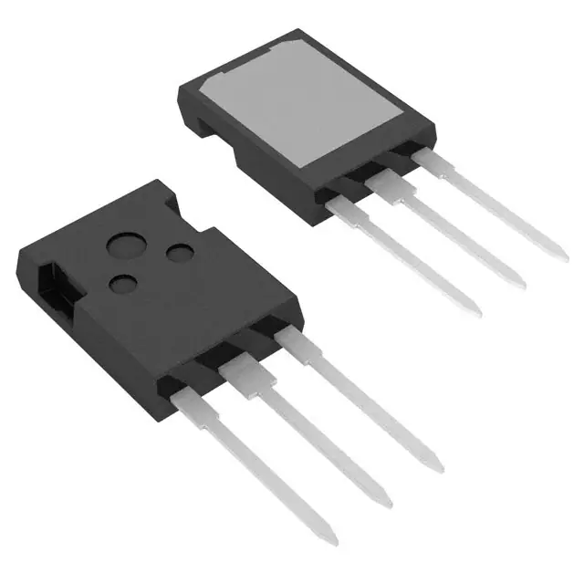
PLUS247 (IXGX)
LE
1700
O
TJ
FC
Maximum Ratings
TE
Symbol
= 1700 V
=
75 A
= 3.3 V
= 290 ns
1700
3.0
Note 1
TJ = 25°C
TJ = 125°C
TJ = 25°C
TJ = 125°C
2.5
3.0
5.0
V
V
500
8
µA
mA
±100
nA
3.3
V
V
DS99071(07/03)
�IXGX
Test Conditions
gfs
IC = IC25; VCE = 10 V
Note 2
Characteristic Values
(TJ = 25°C, unless otherwise specified)
min. typ. max.
25
Cies
Coes
VCE = 25 V, VGE = 0 V, f = 1 MHz
33
S
3500
pF
250
pF
40
pF
155
nC
30
nC
Cres
Qg
Qge
IC = IC90, VGE = 15 V, VCE = 0.5 VCES
51
Qgc
td(on)
Inductive load, TJ = 25°°C
tri
IC = IC90, VGE = 15 V
td(off)
RG = 2.7 Ω, VCE = 0.8 VCES
Note 3
tfi
45
38
270
250
Eoff
td(on)
Inductive load, TJ = 125°°C
tri
IC = IC90, VGE = 15 V
Eon
td(off)
RG = 2.7 Ω, VCE = 0.8 VCES
Note 3
Eoff
BS
RthJC
RthCK
Reverse Diode (FRED) (Note 4)
Symbol
VF
Test Conditions
ns
500
ns
25 mJ
42
ns
6.0
360
mJ
ns
560
ns
22
mJ
0.15
0.35 K/W
K/W
Characteristic Values
(TJ = 25°C, unless otherwise specified)
min. typ. max.
O
IF = 50A, VGE = 0 V, -diF/dt = 800 A/µs
VR = 600 V
2.7
50
150
RthJC
Notes: 1.
ns
500
ns
IF = 70A, VGE = 0 V, Pulse test,
t ≤ 300 µs, duty cycle d ≤ 2 %
IRM
t rr
ns
48
O
tfi
nC
LE
15
PLUS247 Outline (IXGX)
TE
Symbol
32N170H1
V
A
ns
0.4 K/W
Device must be heatsunk for high temperature leakage current
measurements to avoid thermal runaway.
2.
Pulse test, t ≤ 300 µs, duty cycle ≤ 2 %
3.
Switching times may increase for VCE (Clamp) > 0.8 • VCES, higher TJ or
increased RG.
4.
See DH60-18A and IXGH32N170A datasheets for additional
characteristics
IXYS reserves the right to change limits, test conditions, and dimensions.
IXYS MOSFETs and IGBTs are covered by one or more
of the following U.S. patents:
4,835,592 4,881,106 5,017,508 5,049,961 5,187,117 5,486,715 6,306,728B1 6,259,123B1 6,306,728B1
4,850,072 4,931,844 5,034,796 5,063,307 5,237,481 5,381,025 6,404,065B1 6,162,665
6,534,343
�Disclaimer Notice - Information furnished is believed to be accurate and reliable. However, users should independently
evaluate the suitability of and test each product selected for their own applications. Littelfuse products are not designed for,
and may not be used in, all applications. Read complete Disclaimer Notice at www.littelfuse.com/disclaimer-electronics.
�