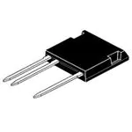
IXLF 19N250A
IC25 = 32 A
VCES = 2500 V
VCE(sat) = 3.2 V
tf
= 250 ns
High Voltage IGBT
in High Voltage
ISOPLUS i4-PACTM
5
1
1
2
5
2
Features
IGBT
Conditions
VCES
TVJ = 25°C to 150°C
Maximum Ratings
VGES
IC25
IC90
TC = 25°C
TC = 90°C
ICM
VCEK
VGE = ±15 V; RG = 47 Ω; TVJ = 125°C
RBSOA, Clamped inductive load; L = 100 µH
Ptot
TC = 25°C
Symbol
Conditions
VCE(sat)
IC = 19 A; VGE = 15 V; TVJ = 25°C
TVJ = 125°C
VGE(th)
IC = 1 mA; VGE = VCE
ICES
VCE = VCES; VGE = 0 V; TVJ = 25°C
TVJ = 125°C
IGES
td(on)
tr
td(off)
tf
Eon
Eoff
2500
V
± 20
V
32
19
A
A
70
1200
A
V
250
W
Characteristic Values
(TVJ = 25°C, unless otherwise specified)
min.
typ. max.
3.2
4.7
5
3.9
V
V
8
V
0.15
mA
mA
500
nA
0.2
VCE = 0 V; VGE = ± 20 V
Inductive load, TVJ = 125°C
VCE = 1500 V; IC = 19 A
VGE = ±15 V; RG = 47 Ω
100
50
600
250
15
30
ns
ns
ns
ns
mJ
mJ
Cies
Coes
Cres
VCE = 25 V; VGE = 0 V; f = 1 MHz
2.28
103
43
nF
pF
pF
QGon
VCE = 1500V; VGE = 15 V; IC = 19 A
142
nC
RthJC
IXYS reserves the right to change limits, test conditions and dimensions.
© 2005 IXYS All rights reserved
• High Voltage IGBT
- substitute for high voltage MOSFETs
with significantly lower voltage drop
and comparable switching speed
- substitute for high voltage thyristors
with voltage control of turn on & turn off
- substitute for electromechanical trigger
and discharge relays
• ISOPLUS i4-PACTM
high voltage package
- isolated back surface
- enlarged creepage towards heatsink
- enlarged creepage between high
voltage pins
- application friendly pinout
- high reliability
- industry standard outline
- UL registered E72873
Applications
• switched mode power supplies
• DC-DC converters
• resonant converters
• laser generators, x ray generators
• discharge circuits
0.5 K/W
0527
Symbol
1-4
�IXLF 19N250A
Component
Conditions
Maximum Ratings
TVJ
Tstg
VISOL
IISOL ≤ 1 mA; 50/60 Hz
FC
mounting force with clip
Symbol
Conditions
dS,dA
dS,dA
C pin - E pin
pin - backside metal
RthCH
with heatsink compound
-55...+150
-55...+125
°C
°C
2500
V~
20...120
N
Characteristic Values
min.
typ. max.
7.0
5.5
Weight
IXYS reserves the right to change limits, test conditions and dimensions.
© 2005 IXYS All rights reserved
mm
mm
0.15
K/W
9
g
0527
Symbol
Dimensions in mm (1 mm = 0.0394")
2-4
�IXLF 19N250A
100
A
IC
50
VGE = 17 V
TJ = 25°C
80
13 V
VGE = 17 V
TJ = 125°C
A
15 V
15 V
40
IC
13 V
11 V
60
30
40
20
11 V
20
9V
10
9V
0
0
0
1
2
3
4
5
6
7
8
9
0
V
1
2
3
4
5
6
VCE
Fig. 1 Typ. Output Characteristics
8
9
V
Fig. 2 Typ. Output Characteristics
10000
80
VCE = 20 V
A
70
f = 1 Mhz
pF
60
Capacitance
50
40
30
Coes
100
TJ = 125°C
20
Cies
1000
Cres
10
TJ = 25°C
10
0
6
7
8
9
10
11
12
13
0
14 V 15
10
20
V
30
40
VCE
VGE
Fig. 3 Typ. Transfer Characteristics
Fig. 4 Capacitance curves
80
20
V
A
VCE = 1500 V
IC = 19 A
TJ = 25°C
15
VGE
ICM
60
10
40
5
20
RG = 47Ω
TJ = 125°C
VCEK < VCES
0
0
0
50
100
QG
150
nC
Fig. 5 Typ. Gate Charge characteristics
IXYS reserves the right to change limits, test conditions and dimensions.
© 2005 IXYS All rights reserved
0
400
800 1200 1600 2000 2400 V
VCE
Fig. 6 Reverse Biased Safe Operating Area
RBSOA
0527
IC
7
VCE
3-4
�IXLF 19N250A
50
60
200
VCE = 1500 V
VGE = ±15 V
mJ
40
ns
160
RG = 47 Ω
TJ = 125°C
Eon
t
tr
30
Eoff
mJ
50
VCE = 1500 V
VGE = ±15 V
40
RG = 47 Ω
TJ = 125°C
120
td(on)
20
1200
ns
1000
800 t
30
600
td(off)
80
20
10
40
Eon
0
0
0
10
20
30
40
10
tf
Eoff
0
A
10
20
IC
35
mJ
30
Eon 25
350
ns
300
td(on)
VCE = 1500 V
VGE = ±15 V
IC = 19 A
TJ = 125°C
250 t
tr
20
2000
ns
mJ
Eoff
Eoff 30
100
5
1500
VCE = 1500 V
VGE = ±15 V
IC = 19 A
TJ = 125°C
150
Eon
0
0
50
100
150
200
Ω 250
RG
t
td(off)
1000
10
500
tf
50
0
40 A
40
20
10
30
IC
Fig. 8 Typ. turn off energy and switching
times versus collector current
200
15
200
0
0
Fig. 7 Typ. turn on energy and switching
times versus collector current
400
0
0
0
50
100
150
200
Ω 250
RG
Fig. 9 Typ. turn on energy and switching
times versus gate resistor
Fig. 10 Typ. turn off energy and switching
times versus gate resistor
1
K/W
ZthJC
0.1
single pulse
0.01
0.001
0.01
IXLF19N250A
0.1
1
s 10
t
IXYS reserves the right to change limits, test conditions and dimensions.
© 2005 IXYS All rights reserved
0527
Fig. 11 Typ. transient thermal impedance
4-4
�Disclaimer Notice - Information furnished is believed to be accurate and reliable. However, users should independently
evaluate the suitability of and test each product selected for their own applications. Littelfuse products are not designed for,
and may not be used in, all applications.Read complete Disclaimer Notice at www.littelfuse.com/disclaimer-electronics.
�
很抱歉,暂时无法提供与“IXLF19N250A”相匹配的价格&库存,您可以联系我们找货
免费人工找货