P r o d u c t
Efficiency Through Technology
B r i e f
650V Ultra Junction X2-Class POWER MOSFETs
Ideal for Power Factor Correction (PFC) circuits and switching power supplies
AUGUST 2015
OVERVIEW
D
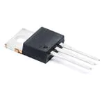
TO-220
S
TO-263
G
IXYS Corporation (NASDAQ: IXYS), a manufacturer of power semiconductors and
integrated circuits for energy efficiency, power management, and motor control
applications, announces a new power MOSFET product line: 650V Ultra Junction
X2-Class Power MOSFETs. With current ratings ranging from 2A to 120A and
on-resistance as low as 24 milliohms, they are well-suited for high-efficiency,
high-speed power switching applications.
These devices are developed using a charge compensation principle and proprietary process technology, resulting in Power MOSFETs with significantly reduced
resistance RDS(on) and gate charge Qg. A low on-state resistance reduces the
conduction losses; it also lowers the energy stored in the output capacitance,
minimizing the switching losses. A low gate charge results in higher efficiency at
light loads as well as lower gate drive requirements. In addition, these MOSFETs
are avalanche rated and exhibit a superior dv/dt performance. Also due to the
positive temperature coefficient of their on-state resistance, they can be
operated in parallel to meet higher current requirements.
Designed for such applications as Power Factor Correction (PFC) circuits,
switched-mode and resonant-mode power supplies, DC-DC converters, AC and
DC motor drives, and robotic and servo control, these MOSFETs enable higher
efficiency, along with high power density and cooler system performance.
The new 650V Ultra Junction Power MOSFETs are available in the following
international standard size packages: TO-252, TO-220 (standard or overmolded),
TO-263, SOT-227, TO-247, PLUS247, ISOPLUS247, and TO-264. Some example
part numbers include IXTY2N65X2, IXTA4N65X2, IXTP8N65X2, and
IXTK102N65X2, with drain current ratings of 2A, 4A, 8A, and 102A, respectively.
FEATURES
Low RDS(ON) and Qg
dv/dt ruggedness
Avalanche rated
Low package inductance
International standard packages
ADVANTAGES
Higher efficiency
High power density
Easy to mount
Space savings
www.ixys.com
TO-220(overmolded)
TO-252
SOT-227
PLUS247
TO-247
TO-264
ISOPLUS247
APPLICATIONS
Power Factor Correction (PFC) circuits
Switched-mode and resonant mode
power supplies
DC-DC converters
AC and DC motor drives
Robotic and servo control
Solar inverters
Lighting control
�Available Parts
Part
Number
VDSS
ID25
RDS(on)
max
TJ=25°C
(Ω)
Ciss
typ
Qg(on)
typ
trr
typ
RthJC
max
PD
max
(pF)
(nC)
(ns)
(°C/W)
(W)
2.3
180
4.3
137
2.27
55
TO-252
TO-220
Package
Type
(V)
TC = 25°C
(A)
IXTY2N65X2
650
2
IXTP2N65X2
650
2
2.3
180
4.3
137
2.27
55
IXTP4N65X2
650
4
0.85
455
8.3
160
1.56
80
TO-220
IXTP8N65X2M
650
4
0.55
800
12
200
3.9
32
TO-220 (overmolded)
IXTY4N65X2
650
4
0.85
455
8.3
160
1.56
80
TO-252
IXTA4N65X2
650
4
0.85
455
8.3
160
1.56
80
TO-263
IXTY8N65X2
650
8
0.5
800
12
200
0.83
150
TO-252
IXTA8N65X2
650
8
0.5
800
12
200
0.83
150
TO-263
IXTP8N65X2
650
8
0.5
800
12
200
0.83
150
TO-263
IXTA12N65X2
650
12
0.3
1100
17
220
0.69
180
TO-263
IXTH12N65X2
650
12
0.3
1100
17
220
0.69
180
TO-247
IXTP12N65X2
650
12
0.3
1100
17
220
0.69
180
TO-220
IXTH34N65X2
650
34
0.105
3120
53
400
0.22
540
TO-247
IXTH48N65X2
650
48
0.068
4420
77
400
0.19
660
TO-247
IXTR102N65X2
650
54
0.033
10900
152
450
0.38
330
ISOPLUS247
IXTH62N65X2
650
62
0.052
5940
104
420
0.16
780
TO-247
IXTN102N65X2
650
76
0.03
10900
152
450
0.21
595
SOT-227
IXTH80N65X2
650
80
0.04
7753
144
400
0.14
890
TO-247
IXTX102N65X2
650
102
0.03
10900
152
450
0.12
1040
PLUS247
IXTK102N65X2
650
102
0.03
10900
152
450
0.12
1040
TO-264
IXTX120N65X2
650
120
0.024
13600
240
410
0.1
1250
PLUS247
IXTK120N65X2
650
120
0.024
13600
240
410
0.1
1250
TO-264
Application Circuits
Application Circuits Legend
Figure 1 illustrates a simplified SMPS circuit diagram that uses an LLC resonant
converter as the primary power conversion element of the circuit. The indicated
SMPS circuit consists of a primary rectifier, power factor correction circuit,
control unit (power supply, MCU, and MOSFET Driver), LLC half-bridge resonant
converter, isolation transformer, and secondary rectifier stage. Two Ultra
Junction X2-Class Power MOSFETs (IXTN102N65X2) are paired to form the LLC
half-bridge resonant converter stage to ensure a fast, space-saving, and energyefficient power switching operation.
M2
VAC Input
M1
Figure 1: SMPS - Half-Bridge Resonant-Mode Converter
Figure 2 portrays a simplified low-side brushed DC motor drive circuit. A rectified
voltage is applied across the brushed DC motor which varies according to a Pulse
Width Modulation (PWM) signal at an inaudible switching frequency (typically
higher than 20 kHz). A DC supply provides a smooth current operation, reducing
(acoustic) motor noise and improving motor efficiency. An X2-Class Power
MOSFET, the IXTK102N65X2 (M1), is used as the main switching element to
ensure an efficient and reliable power switching operation.
Brushed DC
Motor
D1
Power
Supply
VAC Input
M
CDC
MCU
MOSFET
Gate
Driver
M1
Current
R Sensing
Resistor
Pre-charge diode
Figure 2: Brushed DC Motor Drive
D2
Vout
D1
+
IL
Power
Supply
AC mains
CL
CDC
MCU
MOSFET
Gate
Driver
M1
Figure 3 depicts a Power Factor Correction (PFC) circuit– a boost converter
topology. An AC power source is converted into a DC value via a bridge rectifier
stage. This DC value is then processed by the PFC boost converter to keep the
mains current and voltage in phase and provide a DC bus voltage which is higher
than the rectified output. The IXTX102N65X2 (M1) is used as a switch to achieve
high efficiency.
-
Figure 3: Power Factor Correction (PFC) circuit
August 2015
www.ixys.com1.3
�
很抱歉,暂时无法提供与“IXTP4N65X2”相匹配的价格&库存,您可以联系我们找货
免费人工找货