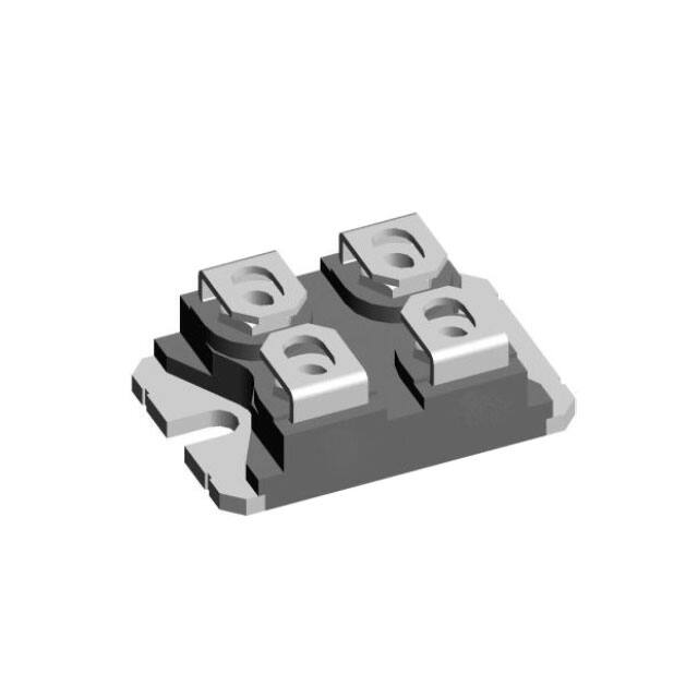
LSIC2SD120N40PA
Silicon Carbide Schottky Diode Datasheet
LSIC2SD120N40PA
1200 V, 2x20 A SiC Schottky Barrier Diode
Product Summary
Characteristic
Value
VRRM
Unit
1200
V
30 °C)
2x20
A
QC (VR: 0-800 V)
125*
nC
IF (TC
*per leg
Features
• Positive temperature coefficient for safe
operation and ease of paralleling
• 175 °C maximum operating junction temperature
• Excellent surge capability
• Extremely fast, temperature-independent
switching behavior
• Dramatically reduced switching losses compared
to Si bipolar diodes
• Zero reverse recovery current
• Copper base plate with AlN isolation for low
thermal resistance
• Isolation voltage: 3000 V
• UL Recognition Pending under File E72873
*Backside is isolated
Agency Approvals and Environmental
Environmental Approvals
(pending)
Pinout Diagram
Applications
• Boost diodes in PFC or DC/DC stages
• Switch-mode power supplies
• Solar inverters
• Uninterruptable power supplies
• Industrial motor drives
• Battery Chargers
• High speed rectifier
*Backside is isolated
1
Specifications are subject to change without notice.
Read complete Disclaimer Notice at www.littelfuse.com/disclaimer-electronics.
© 2020 Littelfuse, Inc.
Revised: 8/24/2020
�LSIC2SD120N40PA
Silicon Carbide Schottky Diode Datasheet
1. Maximum Ratings ...........................................................................................................................................3
2. Package Specifications ...................................................................................................................................3
3. Thermal Characteristics ..................................................................................................................................3
4. Electrical Characteristics .................................................................................................................................3
5. Performance Curves .......................................................................................................................................4
6. VF Model for Simulation ..................................................................................................................................5
7. Package Dimensions ......................................................................................................................................6
8. Part Numbering and Marking ..........................................................................................................................6
9. Packing Options ..............................................................................................................................................6
10. Packing Specifications ..................................................................................................................................7
2
Specifications are subject to change without notice.
Read complete Disclaimer Notice at www.littelfuse.com/disclaimer-electronics.
© 2020 Littelfuse, Inc.
Revised: 8/24/2020
�LSIC2SD120N40PA
Silicon Carbide Schottky Diode Datasheet
1. Maximum Ratings
Characteristic
Symbol
Conditions
Value
Unit
VRRM
-
1200
V
VR
-
1200
V
TC = 25 °C
42 / 84
TC = 100 °C
28 / 56
TC = 130 °C
20 / 40
IFSM
TC = 25 °C, tp = 10 ms, Half sine pulse
145
A
2
TC = 25 °C, tp = 10 ms, Half sine pulse
105
A2s
TC = 25 °C
157 / 314
TC = 110 °C
68 / 136
TJ
-
-55 to 175
°C
TSTG
-
-55 to 150
°C
Repetitive Peak Reverse Voltage
DC Blocking Voltage
Continuous Forward Current
(Per Leg / Component)
IF
Non-repetitive Forward Surge Current
(Per Leg)
2
I t (Per Leg)
I dt
Power Dissipation
(Per Leg / Component)
PTot
Operating Junction Temperature
Storage Temperature
A
W
Note: All ratings are per leg unless otherwise specified
2. Package Specifications
Characteristic
Symbol
Mounting Torque
Striking Distance Through Air
Isolation Voltage
Min
Typ
Max
Screws to heatsink
-
-
1.5
Terminal connection screws
-
-
1.3
dSpp
Terminal to terminal
10.5
-
-
dSpb
Terminal to backside
8.5
-
-
dApp
Terminal to terminal
3.2
-
-
dApb
Terminal to backside
6.8
-
-
-
-
3000
-
-
2500
-
30
-
MD
Creepage Distance on Surface
Value
Conditions
VISOL
Weight
-
50 / 60 Hz - RMS, IISOL
50 / 60 Hz - RMS, IISOL
t = 1 min.
-
Unit
Nm
mm
mm
V
g
3. Thermal Characteristics
Characteristic
Symbol
Value
Unit
Rth,JC,MAX
0.95 / 0.48
°C/W
Maximum Thermal Resistance (Per Leg / Component)
Note: All ratings are per leg unless otherwise specified
4. Electrical Characteristics
Characteristic
Symbol
Forward Voltage
VF
Reverse Current
IR
Total Capacitance
C
Total Capacitive Charge
QC
Capacitive Stored Energy
EC
Value
Conditions
Min
Typ
Max
IF = 20 A, TJ = 25 °C
-
1.5
1.8
IF = 20 A, TJ = 175 °C
-
2.1
-
VR = 1200 V, TJ = 25 °C
-
很抱歉,暂时无法提供与“LSIC2SD120N40PA”相匹配的价格&库存,您可以联系我们找货
免费人工找货