MIXA60HU1200VA
preliminary
XPT IGBT Module
VCES
=
1200 V
I C25
=
85 A
VCE(sat) =
1.8 V
H~ Bridge, Buck / Boost - Combination
Part number
MIXA60HU1200VA
Backside: isolated
10
6
4
5
8 3
1
2
9
7
Features / Advantages:
Applications:
Package: V1-A-Pack
● Easy paralleling due to the positive temperature
coefficient of the on-state voltage
● Rugged XPT design (Xtreme light Punch Through)
results in:
- short circuit rated for 10 µsec.
- very low gate charge
- low EMI
- square RBSOA @ 3x Ic
● Thin wafer technology combined with the XPT design
results in a competitive low VCE(sat)
● SONIC™ diode
- fast and soft reverse recovery
- low operating forward voltage
● Switched-mode power supplies
● Switched reluctance motor drive
● Isolation Voltage: 3600 V~
● Industry standard outline
● RoHS compliant
● Soldering pins for PCB mounting
● Height: 17 mm
● Base plate: DCB ceramic
● Reduced weight
● Advanced power cycling
Disclaimer Notice
Information furnished is believed to be accurate and reliable. However, users should independently
evaluate the suitability of and test each product selected for their own applications. Littelfuse products are not designed for,
and may not be used in, all applications. Read complete Disclaimer Notice at www.littelfuse.com/disclaimer-electronics.
IXYS reserves the right to change limits, conditions and dimensions.
© 2020 IXYS all rights reserved
Data according to IEC 60747and per semiconductor unless otherwise specified
20200729c
�MIXA60HU1200VA
preliminary
Ratings
IGBT
Symbol
VCES
Definition
Conditions
min.
VGES
max. DC gate voltage
VGEM
max. transient gate emitter voltage
I C25
collector current
TC = 25°C
TC = 80 °C
60
A
TC = 25°C
290
W
2.1
V
TVJ =
collector emitter voltage
I C80
Ptot
total power dissipation
VCE(sat)
collector emitter saturation voltage
IC =
55 A; VGE = 15 V
VGE(th)
gate emitter threshold voltage
IC =
2 mA; VGE = VCE
I CES
collector emitter leakage current
VCE = VCES; VGE = 0 V
TVJ = 25°C
1.8
TVJ = 25°C
5.4
5.9
TVJ = 25°C
TVJ = 125 °C
±20
V
±30
V
85
A
V
6.5
0.5
0.2
gate emitter leakage current
VGE = ±20 V
Q G(on)
total gate charge
VCE = 600 V; VGE = 15 V; IC =
t d(on)
turn-on delay time
tr
current rise time
t d(off)
turn-off delay time
tf
current fall time
Eon
turn-on energy per pulse
Eoff
turn-off energy per pulse
RBSOA
reverse bias safe operating area
inductive load
55 A
TVJ = 125 °C
55 A
VGE = ±15 V; R G = 15 Ω
VGE = ±15 V; R G = 15 Ω
short circuit safe operating area
VCEmax = 1200 V
t SC
short circuit duration
VCE = 900 V; VGE = ±15 V
I SC
short circuit current
R G = 15 Ω; non-repetitive
R thJC
thermal resistance junction to case
R thCH
thermal resistance case to heatsink
mA
nA
165
nC
70
ns
40
ns
250
ns
100
ns
4.5
mJ
5.5
mJ
TVJ = 125 °C
VCEmax = 1200 V
SCSOA
V
mA
500
I GES
I CM
max. Unit
1200
V
2.1
TVJ = 125 °C
VCE = 600 V; IC =
typ.
25°C
TVJ = 125 °C
150
A
10
µs
A
200
0.5 K/W
K/W
0.30
Diode
VRRM
max. repetitive reverse voltage
TVJ = 25°C
1200
V
IF25
forward current
TC = 25°C
88
A
TC = 80 °C
59
A
TVJ = 25°C
2.20
V
0.3
mA
IF 80
VF
forward voltage
IF =
IR
reverse current
VR = VRRM
Q rr
reverse recovery charge
I RM
max. reverse recovery current
t rr
reverse recovery time
E rec
reverse recovery energy
R thJC
thermal resistance junction to case
R thCH
thermal resistance case to heatsink
IXYS reserves the right to change limits, conditions and dimensions.
© 2020 IXYS all rights reserved
60 A
TVJ = 125 °C
TVJ = 25°C
TVJ = 125 °C
VR = 600 V
-di F /dt = 1200 A/µs
IF =
60 A; VGE = 0 V
TVJ = 125 °C
1.95
V
1.2
mA
8
µC
60
A
350
ns
2.5
mJ
0.6 K/W
0.2
Data according to IEC 60747and per semiconductor unless otherwise specified
K/W
20200729c
�MIXA60HU1200VA
preliminary
Package
Ratings
V1-A-Pack
Symbol
I RMS
Definition
Conditions
RMS current
per terminal
min.
TVJ
virtual junction temperature
T op
operation temperature
Tstg
storage temperature
-40
max.
100
Unit
A
-40
150
°C
-40
125
°C
125
°C
37
Weight
MD
2
mounting torque
d Spp/App
Date Code
Prod. Index
M
I
X
A
60
HU
1200
VA
Part Number (Typ)
Lot No.:
Data Matrix: Typ (1-19), DC+Prod.Index (20-25), FKT# (26-31)
leer (33), lfd.# (33-36)
Ordering Number
MIXA60HU1200VA
Equivalent Circuits for Simulation
I
V0
terminal to backside
12.0
mm
3600
V
3000
V
Part description
yywwA
Ordering
Standard
R0
=
=
=
=
=
=
=
=
Module
IGBT
XPT IGBT
Gen 1 / std
Current Rating [A]
H~ Bridge, Buck / Boost - Combination
Reverse Voltage [V]
V1-A-Pack
Marking on Product
MIXA60HU1200VA
Delivery Mode
Blister
IGBT
Diode
threshold voltage
1.1
1.22
R0 max
slope resistance *
25.1
13
© 2020 IXYS all rights reserved
Quantity
24
Code No.
518854
T VJ = 150°C
* on die level
V 0 max
IXYS reserves the right to change limits, conditions and dimensions.
Nm
mm
50/60 Hz, RMS; IISOL ≤ 1 mA
t = 1 minute
2.5
6.0
t = 1 second
isolation voltage
g
terminal to terminal
creepage distance on surface | striking distance through air
d Spb/Apb
VISOL
typ.
V
mΩ
Data according to IEC 60747and per semiconductor unless otherwise specified
20200729c
�MIXA60HU1200VA
preliminary
3,6 ±0,5
Outlines V1-A-Pack
0,5 +0,2
35
26
63
31,6
2
max. 0,25
13
17 ±0,25
R2
52 (see 1)
*7
*0
*7 *14
5,5
*14
Ø 6,1
Ø 2,5
1,5
12,2
11,75 ±0,3
=
11,75 ±0,3
=
1x45°
3
4
5
8
9
10
15
6
2
7
4
1
6
*11
5,5
*0
Ø 2,1
*11
6
0,5
*14
*7
25
*0
*7 *14
Marking on product
Aufdruck der Typenbezeichnung
25
Ø 0,8
*
25,75
±0,3
25,75
1 ±0,2
±0,3
Remarks / Bemerkungen:
1. Nominal distance mounting screws on heat sink: 52 mm / Nennabstand Befestigungsschrauben auf Kühlkörper: 52 mm
2. General tolerance / Allgemeintoleranz : DIN ISO 2768 -T1-c
3. Surface treatment of pins: tin plated (Sn) in hot dip / Oberflächenbehandlung der Pins: verzinnt (Sn) im Tauchbad
4. Detail X :�
EJOT PT® self-tapping screws (dimension K25) to be recommended for mounting on PCB �
selbstschneidende Schraube (Größe K25) empfohlen für die PCB-Montage
Take care on the maximum screw length according to board thickness and the maximum hole depth of 6 mm�
Bei der Wahl der Schraubenlänge die PCB-Dicke und die maximale Lochtiefe von 6mm beachten
Recommended mounting torque: 1.5 Nm / Empfohlenes Drehmoment: 1.5 Nm
�
�
10
2 +0,2
6
4
5
8 3
1
2
9
IXYS reserves the right to change limits, conditions and dimensions.
© 2020 IXYS all rights reserved
7
Data according to IEC 60747and per semiconductor unless otherwise specified
20200729c
�MIXA60HU1200VA
preliminary
IGBT
100
100
TVJ = 125°C
25°C
80
100
80
IC 60
IC 60
[A] 40
[A] 40
20
20
13 V
VGE = 15 V
17 V
19 V
11 V
80
IC 60
9V
[A] 40
20
TVJ = 125°C
0
0
0
1
2
TVJ = 25°C
0
0
3
TVJ = 125°C
1
2
3
4
5
6
7
8
9
10 11 12 13
VCE [V]
VCE [V]
VGE [V]
Fig. 1 Typ. output characteristics
Fig. 2 Typ. output characteristics
Fig. 3 Typ. transfer characteristics
10
20
IC = 50 A
VCE = 600 V
8
15
VGE
E
6.0
Eon
RG = 15 Ohm
VCE = 600 V
VGE = ±15 V
TVJ = 125°C
Eoff
Eoff
5.5
6
E
10
5.0
[mJ] 4
[V]
5
[mJ]
4.5
2
0
0
0
50
100
150
4.0
0
200
20
40
60
80
100 120
IC [A]
QG [nC]
12
16
20
24
28
32
RG [Ohm]
Fig. 5 Typ. recovery time
trr versus -diF /dt
Fig. 4 Dynamic parameters
Qr, IRM versus TVJ
IC = 50 A
VCE = 600 V
VGE = ±15 V
TVJ = 125°C
Eon
Fig. 6 Typ. peak forward voltage
VFR and tfr versus diF/dt
1
ZthJC
0.1
[K/W]
0.01
0.001
0.01
0.1
1
10
t [s]
Fig. 7 Transient thermal impedance junction to case
IXYS reserves the right to change limits, conditions and dimensions.
© 2020 IXYS all rights reserved
Data according to IEC 60747and per semiconductor unless otherwise specified
20200729c
�MIXA60HU1200VA
preliminary
Diode
120
14
TVJ = 125°C
25°C
100
90
TVJ = 125°C
VR = 600 V
12
80
IC
10
120A
70
8
60 A
IRR 60
Qrr
60
[A]
TVJ = 125°C
VR = 600 V
80
120A
60 A
30 A
[A] 50
[μC] 6
40
30 A
40
4
20
30
2
0
0
1
2
3
600
800
1000
20
600
1200
-diF /dt [A/μs]
VCE [V]
1200
Fig. 3 Typ. peak reverse current
IRM versus di/dt
700
4.0
TVJ = 125°C
VR = 600 V
TVJ = 125°C
VR = 600 V
600
trr
1000
-diF /dt [A/μs]
Fig. 2 Typ. reverse recovery
charge Qrr versus di/dt
Fig. 1 Typ. Forward current
versus VF
800
120A
3.2
500
Erec
[ns] 400
120A
60 A
2.4
30 A
[mJ] 1.6
60 A
300
0.8
30 A
200
600
800
1000
0.0
600
1200
Fig. 5 Typ. recovery time
trr versus -diF /dt
Fig. 4 Dynamic parameters
Qr, IRM versus TVJ
800
1000
1200
-diF /dt [A/μs]
-diF /dt [A/μs]
Fig. 6 Typ. recovery energy
Erec versus -di/dt
1
ZthJC
0.1
[K/W]
Ri
ti
[K/W] [s]
1
2
3
4
0.01
0.001
0.01
0.1
1
0.137
0.1
0.233
0.13
0.0025
0.03
0.03
0.08
10
t [s]
Fig. 7 Transient thermal impedance junction to case
IXYS reserves the right to change limits, conditions and dimensions.
© 2020 IXYS all rights reserved
Data according to IEC 60747and per semiconductor unless otherwise specified
20200729c
�
很抱歉,暂时无法提供与“MIXA60HU1200VA”相匹配的价格&库存,您可以联系我们找货
免费人工找货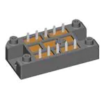


 工商网监
湘ICP备2023018690号
工商网监
湘ICP备2023018690号
