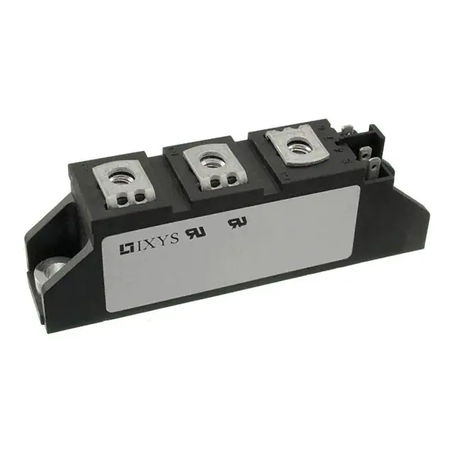
VMO60-05F
Preliminary
VDSS = 500 V
ID25
= 60 A
RDS(on) = 65 mΩ
HiPerFET™
Power Module
High dv/dt, Low trr, HDMOS™ Family
Part number
VMO60-05F
E72873
1
5
6
3
Features / Advantages:
Applications:
Package: TO-240AA
• Single MOSFET
• Direct copper bonded Al2O3 ceramic
base plate
• Low RDS(on) HDMOSTM process
• Low package inductance for high
speed switching
• Kelvin source contact
• Keyed twin plugs
• High power density
• Low losses
• Switched-mode and resonant-mode
power supplies
• Uninterruptible power supplies (UPS)
• DC servo and robot drives
• DC choppers
• Isolation Voltage: 4800 V~
• Industry standard outline
• RoHS compliant
• Soldering pins for PCB mounting
• Base plate: DCB ceramic
• Reduced weight
• Advanced power cycling
Disclaimer Notice
Information furnished is believed to be accurate and reliable. However, users should independently
evaluate the suitability of and test each product selected for their own applications. Littelfuse products are not designed for,
and may not be used in, all applications. Read complete Disclaimer Notice Disclaimer Notice at www.littelfuse.com/disclaimer-electronics.
IXYS reserves the right to change limits, test conditions and dimensions.
© 2020 IXYS All rights reserved
20200727a
1-4
�VMO60-05F
Preliminary
MOSFETs
Ratings
Symbol
Definitions
VDSS
drain source breakdown voltage
Conditions
min.
VDGR
drain gate voltage
RGS = 10 kΩ
VGS
VGSM
gate source voltage
max. transient gate source voltage
Continuous
Transient
ID25
ID100
IDM
continuous drain current
drain current
maximum pulsed drain current
Ptot
total power dissipation
VDSS
drain source breakdown voltage
VGS = 0 V
VGS(th)
gate threshold voltage
VDS = VGS; ID = 24 mA
IGSS
gate source leakage current
VGS = ±20 V DC; VDS = 0
IDSS
drain source leakage current
VDS = VDSS;
VGS = 0 V
VDS = 0.8 • VDSS; VGS = 0 V
TVJ = 25°C
TVJ = 125°C
RDS(on)
staticdrain source on resistance
VGS = 10 V; ID = 0.5 • ID25
TVJ = 25°C
typ.
max. Unit
TVJ = 25°C to150°C
500
V
TVJ = 25°C to150°C
500
V
±20
±30
V
V
TC = 25°C
TC = 100°C
TC = 25°C
60
37
240
A
A
A
TC = 25°C
590
W
tp = 10 µs, pulse width limited by TJM
500
V
2
4
65
V
500
nA
600
3
µA
mA
75
mΩ
Pulse test, t ≤ 300 µs, duty cycle d ≤ 2 %
gfs
forward transconductance
VDS = 10 V; ID = 0.5 • ID25 pulsed
Ciss
Coss
Crss
input capacitance
output capacitance
reverse transfer (Miller) capacitance
VGS = 0 V; VDS = 25 V; f = 1 MHz
td(on)
tr
td(off)
tf
turn-on delay time
current rise time
turn-off delay time
current fall time
Qg
Qgs
Qgd
total gate charge
gate source charge
gate drain (Miller) charge
RthJC
RthJH
thermal resistance junction to case
thermal resistance junction to heatsink
30
60
S
12.6
1.35
0.405
nF
nF
nF
VGS = 10 V; VDS = 0.5 • VDSS; ID = 0.5 • ID25
RG = 1 Ω (external), resistive load
50
45
250
30
ns
ns
ns
ns
VGS = 10 V; VDS = 0.5 • VDSS; ID = 0.5 • ID25
405
90
180
nC
nC
nC
with heat transfer paste
0.41
0.21 K/W
K/W
Source-Drain Diodes
Ratings
Symbol
Definitions
Conditions
IS
continuous source current
VGS = 0 V
ISM
maximum pulsed source current
VSD
trr
min.
typ.
max.
60
A
Repetitive; pulse width limited by TJM
240
A
forward voltage drop
IF = IS; VGS = 0 V
Pulse test, t ≤ 300 µs, duty cycle d ≤ 2 %
1.5
V
reverse recovery time
IF = IS, -di/dt = 100 A/µs; VDS = 100 V; VGS = 0 V
250
ns
Data according to IEC 60747 and refer to a single thyristor/diode unless otherwise stated. TJ = 25°C, unless otherwise specified
IXYS reserves the right to change limits, test conditions and dimensions.
© 2020 IXYS All rights reserved
20200727a
2-4
�VMO60-05F
Preliminary
Package
TO-240AA
Ratings
Symbol
Definitions
Conditions
IRMS
RMS current
per terminal
TVJ
virtual junction temperature
TVJM
maximum virtual junction temperature
Tstg
storage temperature
min.
-40
-40
Weight
MD
MT
dSpp/App
dSpb/Apb
VISOL
typ.
max.
Unit
200
A
150
°C
150
°C
125
°C
76
mounting torque
terminal torque
2.5
2.5
creepage distance on surface | striking distance through air
isolation voltage
t = 1 second
t = 1 minute
IXYS reserves the right to change limits, test conditions and dimensions.
© 2020 IXYS All rights reserved
g
4
4
Nm
Nm
terminal to terminal
13.0
9.7
mm
terminal to backside
16.0
16.0
mm
50/60 Hz, RMS, IISOL < 1 mA
4800
V
4000
V
20200727a
3-4
�VMO60-05F
Preliminary
Outlines
TO-240AA
Dimensions in mm (1 mm = 0.0394")
23.5
29.7 ±0.2
+0.4
7.5 - 01
28.5
65 x 19
0.25
30.2 +0.8
- 02
3.5
A 2.8 - 0.8
DIN 46244
General tolerance: DIN ISO 2768 class „c“
92 ±0.5
5.5 ±0.1
6
10
M5
6.9 6.9
10 ±0.1
14.8
20.8 ±0.25
80 ±0.3
25 ±0.3
65 ±0.3
Optional accessories for modules
Keyed gate/cathode twin plugs with wire length = 350 mm, gate = white, cathode = red
Type ZY 200L (L = Left for pin pair 4/5)
UL 758, style 3751
Type ZY 200R (R = Right for pin pair 6/7)
1
5
6
3
IXYS reserves the right to change limits, test conditions and dimensions.
© 2020 IXYS All rights reserved
20200727a
4-4
�
很抱歉,暂时无法提供与“VMO60-05F”相匹配的价格&库存,您可以联系我们找货
免费人工找货