High Frequency Ceramic Solutions
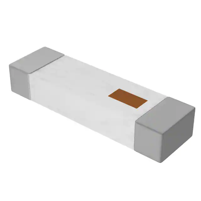
2.45 GHz High Gain SMD Chip Antenna
Detail Specification:
New Global P/N 2450AT45A0100001
Legacy P/N 2450AT45A100
8/24/2022
General Specifications
New Global Part Number
Page 1 of 11
Let us help you with the antenna design, optimization, and tuning!
https://www.johansontechnology.com/ask-a-question
2450AT45A0100001
Frequency Range (MHz)
2400 - 2500
Input Power
3W max. (CW)
Impedance
50 Ω
Operating Temp
-40°C to +125°C
+5 to +35°C
Recommended Storage
Conditions and Period for
unused Product on T&R
Humidity 45 - 75% RH
Reel Quantity (pcs/reel)
1,000
18 months max.
Top
Peak Gain Based on Orientation
Mounting Considerations 1:
"Vertical Orientation"
(Page 2)
2.2 dBi typ. (XZ-V)
Mounting Considerations 2:
"Horizontal Orientation
Type A" (Pages 5)
1.5 dBi typ. (XZ-V)
Mounting Considerations 3:
"Horizontal Orientation
Type B" (Pages 8)
Bottom
1.3 dBi typ. (XZ-V)
Part Number Explanation (See last page more more info on new and legacy part numbers)
Packing Style
P/N Suffix
Bulk (loose pcs.)
Suffix = B
e.g. 2450AT45A0100001B
T&R
Suffix = E
e.g. 2450AT45A0100001E
100% Tin
Suffix = None
e.g. 2450AT45A0100001B (B or E)
2450AT45A0100001CE1 (Page 2)
Evaluation Boards
(1-port SMA antenna test 2450AT45A0100001CE2 (Page 5)
boards, pre-tuned)
2450AT45A0100001CE3 (Page 8)
Mechanical Specifications
In
mm
L
0.374 ± 0.008
9.50 ± 0.20
W
0.079 ± 0.008
2.00 ± 0.20
T
0.047 +.004/-.008
1.20 +0.1/-0.2
a
0.020 ± 0.012
0.50 ± 0.30
Terminal Configuration
W
L
a
T
No
Function
1
Feeding Point
2
NC
2
1
Johanson Technology, Inc. reserves the right to make design changes without notice.
All sales are subject to Johanson Technology, Inc. terms and conditions.
https://www.johansontechnology.com
4001 Calle Tecate • Camarillo, CA 93012 • TEL 805.389.1166 FAX 805.389.1821
Ver 3.2
2021 Johanson Technology, Inc. All Rights Reserved
�High Frequency Ceramic Solutions
2.45 GHz High Gain SMD Chip Antenna
Detail Specification:
New Global P/N 2450AT45A0100001
Legacy P/N 2450AT45A100
8/24/2022
Page 2 of 11
Typical Electrical Specs for "Vertical Orientation" (T=25°C)
Frequency Range
2400 - 2500 MHz
Return Loss
9.5 dB min.
Peak Gain
2.2 dBi typ. (XZ-V)
Average Gain
1.0 dBi typ. (XZ-V)
Mounting Considerations 1: "Vertical Orientation"
Mount these devices with brown mark facing up.
*Line width should be designed to provide 50Ω impedance matching characteristics.
1.0
GND
C
*
1.5pF
GND
Units in mm
10.5
7.5
*
"C" Dimension will depend on the
width of the trace required for it to
have a 50ohm characteristic
impedance (i.e. coplanar waveguide
theory)
1.8
)
)
3.9nH
Want the layout file of this? Send us a
message at:
https://www.johansontechnology.com/aska-question
Let us help you design this antenna
to your PCB and/or optimize your
layout for best radiated performance.
Send us a message by clicking on the
link above.
)
GND
40
12
50Ω
Feed
Line
)
1.5pF
20
3.9nH
GND
Orderable Evaluation board:
p/n: 2450AT45A0100001CE1
No Ground
or Metals
underneath
Note: It is recommended that the designer leave available slots for a "pi" (or shunt-series-shunt) network. The antenna
matching network values above are used when antenna is mounted on Johanson's evaluation board. The matching values
on client's PCB will be different, go to: https://www.johansontechnology.com/tuning and see how to obtain the new values.
If you need further help, contact our RF Applications Eng Team at: https://www.johansontechnology.com/ask-a-question
Johanson Technology, Inc. reserves the right to make design changes without notice.
All sales are subject to Johanson Technology, Inc. terms and conditions.
https://www.johansontechnology.com
4001 Calle Tecate • Camarillo, CA 93012 • TEL 805.389.1166 FAX 805.389.1821
Ver 3.2
2021 Johanson Technology, Inc. All Rights Reserved
�High Frequency Ceramic Solutions
2.45 GHz High Gain SMD Chip Antenna
Detail Specification:
New Global P/N 2450AT45A0100001
Legacy P/N 2450AT45A100
8/24/2022
Page 3 of 11
Typical Electrical Characteristics for "Vertical Orientation" (T=25°C)
Return Loss
a) Without a Matching Circuit
b) With a Matching Circuit
Johanson Technology, Inc. reserves the right to make design changes without notice.
All sales are subject to Johanson Technology, Inc. terms and conditions.
https://www.johansontechnology.com
4001 Calle Tecate • Camarillo, CA 93012 • TEL 805.389.1166 FAX 805.389.1821
Ver 3.2
2021 Johanson Technology, Inc. All Rights Reserved
�High Frequency Ceramic Solutions
2.45 GHz High Gain SMD Chip Antenna
Detail Specification:
New Global P/N 2450AT45A0100001
Legacy P/N 2450AT45A100
8/24/2022
Page 4 of 11
Typical Radiation Patterns for "Vertical Orientation" (T=25°C)
XY cut @2.45GHz
Vertical
Horizontal
)
XY-V/XY-H
Z
180°
)
X
270°
90°
Y
0°
XZ-V/XZ-H
XY-cut scanning direction
XZ cut @2.45GHz
Vertical
Horizontal
Y
180°
X
270°
90°
Z
0°
XZ-cut scanning direction
)
YZ-V/YZ-H
YZ cut @2.45GHz
Vertical
Horizontal
X
180°
Y
270°
90°
Z
0°
YZ-cut scanning direction
Johanson Technology, Inc. reserves the right to make design changes without notice.
All sales are subject to Johanson Technology, Inc. terms and conditions.
https://www.johansontechnology.com
4001 Calle Tecate • Camarillo, CA 93012 • TEL 805.389.1166 FAX 805.389.1821
Ver 3.2
2021 Johanson Technology, Inc. All Rights Reserved
�High Frequency Ceramic Solutions
2.45 GHz High Gain SMD Chip Antenna
Detail Specification:
New Global P/N 2450AT45A0100001
Legacy P/N 2450AT45A100
8/24/2022
Page 5 of 11
Typical Electrical Specs for "Horizontal Orientation Type A" (T=25°C)
Frequency Range
2400 - 2500 MHz
Return Loss
9.5 dB min.
Peak Gain
1.5 dBi typ. (XZ-V)
Average Gain
0.0 dBi typ. (XZ-V)
Mounting Considerations 2: "Horizontal Orientation Type A"
Mount these devices with brown mark facing up.
*Line width should be designed to provide 50Ω impedance matching characteristics.
6.8
GND
Units in mm
1.8
1.5pF
*
1.5
"C" Dimension will depend
on the width of the trace
required for it to have a
50ohm characteristic
impedance (i.e. coplanar
waveguide theory)
)
C
)
7.5
GND
Want the layout file of this? Send us a
message at:
1.5
5.0
1.8
https://www.johansontechnology.com/aska-question
Let us help you design this antenna
to your PCB and/or optimize your
layout for best radiated performance.
Send us a message by clicking on the
link above.
This 50Ω trace Feedline can be as short as
needed, this length is just for reference to
our EVB.
6.8
40
20
GND
Orderable Evaluation board:
p/n: 2450AT45A0100001CE2
GND
19
No Ground,
Metal Layer
Keep-Out
Note: It is recommended that the designer leave available slots for a "pi" (or shunt-series-shunt) network. The antenna
matching network values above are used when antenna is mounted on Johanson's evaluation board. The matching values
on client's PCB will be different, go to: https://www.johansontechnology.com/tuning and see how to obtain the new values.
If you need further help, contact our RF Applications Eng Team at: https://www.johansontechnology.com/ask-a-question
Johanson Technology, Inc. reserves the right to make design changes without notice.
All sales are subject to Johanson Technology, Inc. terms and conditions.
https://www.johansontechnology.com
4001 Calle Tecate • Camarillo, CA 93012 • TEL 805.389.1166 FAX 805.389.1821
Ver 3.2
2021 Johanson Technology, Inc. All Rights Reserved
�High Frequency Ceramic Solutions
2.45 GHz High Gain SMD Chip Antenna
Detail Specification:
New Global P/N 2450AT45A0100001
Legacy P/N 2450AT45A100
8/24/2022
Page 6 of 11
Typical Electrical Characteristics for "Horizontal Orientation Type A" (T=25°C)
Return Loss
)
Johanson Technology, Inc. reserves the right to make design changes without notice.
All sales are subject to Johanson Technology, Inc. terms and conditions.
https://www.johansontechnology.com
4001 Calle Tecate • Camarillo, CA 93012 • TEL 805.389.1166 FAX 805.389.1821
Ver 3.2
2021 Johanson Technology, Inc. All Rights Reserved
�High Frequency Ceramic Solutions
2.45 GHz High Gain SMD Chip Antenna
Detail Specification:
New Global P/N 2450AT45A0100001
Legacy P/N 2450AT45A100
8/24/2022
Page 7 of 11
Typical Radiation Patterns for "Horizontal Orientation Type A" (T=25°C)
)
)
XY-V/XY-H
)
Z
180°
XY cut @2.45GHz
Vertical
Horizontal
)
X
270°
90°
Y
0°
XZ-V/XZ-H
XY-cut scanning direction
Y
XZ cut @2.45GHz
Vertical
Horizontal
180°
X
270°
90°
Z
0°
XZ-cut scanning direction
)
YZ-V/YZ-H
YZ cut @2.45GHz
Vertical
Horizontal
X
180°
Y
270°
90°
Z
0°
YZ-cut scanning direction
Johanson Technology, Inc. reserves the right to make design changes without notice.
All sales are subject to Johanson Technology, Inc. terms and conditions.
https://www.johansontechnology.com
4001 Calle Tecate • Camarillo, CA 93012 • TEL 805.389.1166 FAX 805.389.1821
Ver 3.2
2021 Johanson Technology, Inc. All Rights Reserved
�High Frequency Ceramic Solutions
2.45 GHz High Gain SMD Chip Antenna
Detail Specification:
New Global P/N 2450AT45A0100001
Legacy P/N 2450AT45A100
8/24/2022
Page 8 of 11
Typical Electrical Specs for "Horizontal Orientation Type B" (T=25°C)
Frequency Range
2400 - 2500 MHz
9.5 dB min.
Return Loss
Peak Gain
1.3 dBi typ. (XZ-V)
Average Gain
0.6 dBi typ. (XZ-V)
Mounting Considerations 3: "Horizontal Orientation Type B"
Mount these devices with brown mark facing up.
* Line width should be designed to provide 50Ω impedance matching characteristics.
0.5
Units in mm
10.5
GND
7.5
0 Ohm
1.8
*
GND
1.5
1.5
This 50Ω Feedline can be as short as needed,
this length is just for reference to our EVB
Want the layout file of this? Send us a
message at:
22.5
https://www.johansontechnology.com/aska-question
8.5
GND
11.5
Let us help you design this antenna
to your PCB and/or optimize your
layout for best radiated performance.
Send us a message by clicking on the
11.5
link above.
Orderable Evaluation board:
p/n: 2450AT45A0100001CE3
40
No Ground
5
9.5
Note: It is recommended that the designer leave available slots for a "pi" (or shunt-series-shunt) network. The antenna
matching network values above are used when antenna is mounted on Johanson's evaluation board. The matching values
on client's PCB will be different, go to: https://www.johansontechnology.com/tuning and see how to obtain the new values.
If you need further help, contact our RF Applications Eng Team at: https://www.johansontechnology.com/ask-a-question
Johanson Technology, Inc. reserves the right to make design changes without notice.
All sales are subject to Johanson Technology, Inc. terms and conditions.
https://www.johansontechnology.com
4001 Calle Tecate • Camarillo, CA 93012 • TEL 805.389.1166 FAX 805.389.1821
Ver 3.2
2021 Johanson Technology, Inc. All Rights Reserved
�High Frequency Ceramic Solutions
2.45 GHz High Gain SMD Chip Antenna
Detail Specification:
New Global P/N 2450AT45A0100001
Legacy P/N 2450AT45A100
8/24/2022
Page 9 of 11
Typical Electrical Characteristics for "Horizontal Orientation Type B" (T=25°C)
Return Loss
)
Johanson Technology, Inc. reserves the right to make design changes without notice.
All sales are subject to Johanson Technology, Inc. terms and conditions.
https://www.johansontechnology.com
4001 Calle Tecate • Camarillo, CA 93012 • TEL 805.389.1166 FAX 805.389.1821
Ver 3.2
2021 Johanson Technology, Inc. All Rights Reserved
�High Frequency Ceramic Solutions
2.45 GHz High Gain SMD Chip Antenna
Detail Specification:
New Global P/N 2450AT45A0100001
Legacy P/N 2450AT45A100
8/24/2022
Page 10 of 11
Typical Radiation Patterns for "Horizontal Orientation Type B" (T=25°C)
)
XY-V/XY-H
Z
)
)
180°
XY cut @2.45GHz
Vertical
Horizontal
)
X
270°
90°
Y
0°
XZ-V/XZ-H
XY-cut scanning direction
Y
XZ cut @2.45GHz
Vertical
Horizontal
180°
X
270°
90°
Z
0°
XZ-cut scanning direction
)
YZ-V/YZ-H
X
180°
YZ cut @2.45GHz
Vertical
Horizontal
Y
270°
90°
Z
0°
YZ-cut scanning direction
Johanson Technology, Inc. reserves the right to make design changes without notice.
All sales are subject to Johanson Technology, Inc. terms and conditions.
https://www.johansontechnology.com
4001 Calle Tecate • Camarillo, CA 93012 • TEL 805.389.1166 FAX 805.389.1821
Ver 3.2
2021 Johanson Technology, Inc. All Rights Reserved
�High Frequency Ceramic Solutions
2.45 GHz High Gain SMD Chip Antenna
Detail Specification:
New Global P/N 2450AT45A0100001
Legacy P/N 2450AT45A100
8/24/2022
Page 11 of 11
Antenna tuning, optimization, and validation services:
https://www.johansontechnology.com/ipc-antenna-services
For more antennas and to download measured S-parameters, go to:
https://www.johansontechnology.com/antennas
Soldering Information
https://www.johansontechnology.com/ipcsoldering-profile
MSL Info
https://www.johansontechnology.com/msl-rating
Packaging Information
https://www.johansontechnology.com/tape-reel-packaging
For layout review contact our applications team at:
https://www.johansontechnology.com/ask-a-question
RoHS Compliance
https://www.johansontechnology.com/rohs-compliance
Johanson's New Global Part Number Schema
Johanson has instituted a new Global Part Numbering (GPN) system. Only the part number is changing. The parts
are produced with the exact same materials, manufacturing processes, manufacturing controls, dimensions, physical
attributes and testing as the parts supplied with the legacy part numbers.
A database for part number crosses can be accessed at:
https://www.johansontechnology.com/pn-search
Johanson Technology, Inc. reserves the right to make design changes without notice.
All sales are subject to Johanson Technology, Inc. terms and conditions.
https://www.johansontechnology.com
4001 Calle Tecate • Camarillo, CA 93012 • TEL 805.389.1166 FAX 805.389.1821
Ver 3.2
2021 Johanson Technology, Inc. All Rights Reserved
�