Printed Circuit Board Mount Power Film Capacitors
C4C, Axial Round, 850 – 3,000 VDC/450 – 750 VAC
Overview
Applications
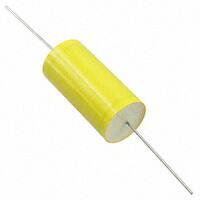
The C4C capacitor is a polypropylene metallized film and
polyester double-metallized foil capacitor with a polyester
tape wrapping filled with resin, and uses tinned
copper wires.
Typical applications include snubber, clamping, resonance,
coupling/decoupling, pulse, and blocking.
Benefits
• Self-healing
• Low loss
• High ripple current
• High contact reliability
• Suitable for high frequency applications
• PP metallized and PET double-sided metallized foil
Part Number System
C4
C
A
M
U
B
3100
AA
Series
Type
Fire
Protection
Rated
Voltage
(VDC)
Insulation
Lead
Diameter
(mm)
Capacitance
Code (pF)
Packaging
C4 = MKP
Capacitors
C = Round
body,
snubber
application
A = No fire
retardant
S = Fire
retardant
(on request)
M = 850
P = 1,200
W = 2,000
Y = 3,000
U = Polyester
B = 0.8
tape and resin C = 1.0
protection
D = 1.2
0 = Uninsulated
(upon request,
but not in
combination
with Fire
Protection "S")
Digits two – four indicate
the first three digits of the
capacitance value. First
digit indicates the number
of zeros to be added.
0
J
Capacitor
Length Tolerance
(mm)
AA = Bulk (Bag)
– straight leads
see "Dimensions
Table"
0 = 33
1 = 44
3 = 58
J = 5%
K = 10%
Built Into Tomorrow
© KEMET Electronics Corporation • One East Broward Boulevard�
Fort Lauderdale, FL 33301 USA • 954-766-2800 • www.kemet.com
F3042_C4C_AXIAL • 8/14/2023
1
�Power and AC Film Capacitors – Printed Circuit Board Mount Power Film Capacitors
C4C, Axial Round, 850 – 3,000 VDC/450 – 750 VAC
Dimensions – Millimeters
SIDE VIEW
FRONT VIEW
LL
L
LL
D
d
D
L
d
LL
Maximum
Maximum
Nominal
±5
10 – 14
33
0.8
40
14.5 – 21.5
33
1
40
19 – 23
44
1
40
23.5 – 33.5
44
1.2
40
28.5 – 32
58
1.2
40
Qualification
Reference Standards
Application Class (DIN 40040)
Vibration Strength
VDE 0560, IEC 61071, EN 61071
GPE/LS
DIN 40040, Table 6, Class V
© KEMET Electronics Corporation • One East Broward Boulevard�
Fort Lauderdale, FL 33301 USA • 954-766-2800 • www.kemet.com
F3042_C4C_AXIAL • 8/14/2023
2
�Power and AC Film Capacitors – Printed Circuit Board Mount Power Film Capacitors
C4C, Axial Round, 850 – 3,000 VDC/450 – 750 VAC
Performance Characteristics
Temperature Range
Maximum Permissible Ambient
Temperature
IEC Climatic Category
Peak Non-Repetitive Maximum
Current
Test Voltage Terminal to
Terminal (VTT)
Test Voltage Terminal to Case
(VTC)
Insulation Resistance Test
Conditions
Dissipation Factor (DF)
Capacitance Deviation in
Operating Temperature Range
of -40°C to +85°C
Life Expectancy
Failure Quota
Change of Capacitance vs.
Operating Time
Protection
Flame Retardant (IEC 384–1)
Leads
Installation
Damp Heat Test
−40°C to +85°C
+70°C
40/85/56 according to IEC 68–1
IPKR x 1.5
2 Vn for 10 seconds
3 k VDC 50 Hz for 60 seconds
Temperature: +25°C ±5%
Voltage charge time: 1 minute
Test voltage: 100 VDC
Typical value (Ris x C): 3,000
seconds
≤ 5 x 10⁻⁴ at 1 kHz and 20°C
±1.5% maximum on capacitance
value measured at +20°C
≥ 30,000 hours at VRMS,
≥ 100,000 hours at Vn
300/109 components per hour
−3% after 30,000 hours at VRMS
or after 100,000 hours at Vn
Polyester wrapping with epoxy
resin fill
Standard execution: non-flame
retardant
On request: flame retardant
execution Category C
Tinned copper
(lead content = 5%)
Any position
Test Conditions
Relative humidity: 93% ±2%
Temperature: +40°C
Test duration: 56 days
Capacitance change: ≤ ±5%
DF change: ≤ 50% of nominal
value at 1 kHz
Insulation resistance: ≥ 50% of
limit value
© KEMET Electronics Corporation • One East Broward Boulevard�
Fort Lauderdale, FL 33301 USA • 954-766-2800 • www.kemet.com
F3042_C4C_AXIAL • 8/14/2023
3
�Power and AC Film Capacitors – Printed Circuit Board Mount Power Film Capacitors
C4C, Axial Round, 850 – 3,000 VDC/450 – 750 VAC
Table 1 – Ratings & Part Number Reference
Cap
Value
(µF)
VDC
0.1
0.15
0.22
0.33
0.47
0.68
1
1.5
2
2.2
2.5
0.047
0.068
0.1
0.15
0.22
0.33
0.47
0.68
1
1.2
1.5
0.022
0.033
0.047
0.068
0.1
0.15
0.22
0.33
0.47
0.56
0.68
0.0068
0.01
0.015
0.022
0.033
0.047
0.068
0.1
0.15
0.22
850
850
850
850
850
850
850
850
850
850
850
1,200
1,200
1,200
1,200
1,200
1,200
1,200
1,200
1,200
1,200
1,200
2,000
2,000
2,000
2,000
2,000
2,000
2,000
2,000
2,000
2,000
2,000
3,000
3,000
3,000
3,000
3,000
3,000
3,000
3,000
3,000
3,000
450
450
450
450
450
450
450
450
450
450
450
500
500
500
500
500
500
500
500
500
500
500
630
630
630
630
630
630
630
630
630
630
630
750
750
750
750
750
750
750
750
750
750
Capacitance
Value (µF)
VDC
VAC
VAC
Peak
VDC
Maximum
Dimensions
(mm)
Ripple
Current
Peak
Current
ESR
(Max)
dV/dt
(V/
100 kHz µs)
(mΩ)
Packaging
Quantity
Part Number
D
L
100 kHz
70°C (A)
(A)
1,200
1,200
1,200
1,200
1,200
1,200
1,200
1,200
1,200
1,200
1,200
1,600
1,600
1,600
1,600
1,600
1,600
1,600
1,600
1,600
1,600
1,600
2,400
2,400
2,400
2,400
2,400
2,400
2,400
2,400
2,400
2,400
2,400
3,500
3,500
3,500
3,500
3,500
3,500
3,500
3,500
3,500
3,500
10.5
12.5
15.5
18.5
21.5
21
25
30.5
28.5
29.5
31.5
10
12
14
17.5
20.5
20
23
27.5
33
29
32
10.5
12.5
15
17.5
20.5
19.5
23.5
28.5
33.5
29
32
10
12
14.5
17
20.5
19
22.5
27
32
31
33
33
33
33
33
44
44
44
58
58
58
33
33
33
33
33
44
44
44
44
58
58
33
33
33
33
33
44
44
44
44
58
58
33
33
33
33
33
44
44
44
44
58
5
7
9
9
9
9
12
12
12
12
12
4
5
7
9
9
9
9
12
12
12
12
3
4
6
7
9
9
12
12
12
12
12
2
3
4
5
6
7
9
12
12
12
45
68
99
149
212
204
300
450
400
440
500
33
48
70
105
154
149
212
306
450
330
413
25
38
54
78
115
105
154
231
329
224
272
14.5
21
32
46
69
59
85
125
188
165
16.6
11.5
8.1
5.8
4.6
5.1
3.8
3.1
3.8
3.7
3.5
27.1
19.1
13.4
9.2
6.8
7.2
5.6
4.2
3.5
4.5
4
48.2
32.5
23
16.3
11.6
11.3
8
5.9
4.8
6.1
5.4
132
90.3
60.5
41.6
28.3
25.7
18.3
12.8
9.2
9.5
450
450
450
450
450
300
300
300
200
200
200
700
700
700
700
700
450
450
450
450
275
275
1,150
1,150
1,150
1,150
1,150
700
700
700
700
400
400
2,100
2,100
2,100
2,100
2,100
1,250
1,250
1,250
1,250
750
300
300
200
150
100
100
50
50
30
30
30
400
300
250
150
100
100
70
50
50
30
30
400
300
200
150
100
100
70
50
50
30
30
400
300
200
150
100
100
70
50
50
30
C4C(1)M(2)B3100AA0(3)
C4C(1)M(2)B3150AA0(3)
C4C(1)M(2)C3220AA0(3)
C4C(1)M(2)C3330AA0(3)
C4C(1)M(2)C3470AA0(3)
C4C(1)M(2)C3680AA1(3)
C4C(1)M(2)D4100AA1(3)
C4C(1)M(2)D4150AA1(3)
C4C(1)M(2)D4200AA3(3)
C4C(1)M(2)D4220AA3(3)
C4C(1)M(2)D4250AA3(3)
C4C(1)P(2)B2470AA0(3)
C4C(1)P(2)B2680AA0(3)
C4C(1)P(2)B3100AA0(3)
C4C(1)P(2)C3150AA0(3)
C4C(1)P(2)C3220AA0(3)
C4C(1)P(2)C3330AA1(3)
C4C(1)P(2)C3470AA1(3)
C4C(1)P(2)D3680AA1(3)
C4C(1)P(2)D4100AA1(3)
C4C(1)P(2)D4120AA3(3)
C4C(1)P(2)D4150AA3(3)
C4C(1)W(2)B2220AA0(3)
C4C(1)W(2)B2330AA0(3)
C4C(1)W(2)C2470AA0(3)
C4C(1)W(2)C2680AA0(3)
C4C(1)W(2)C3100AA0(3)
C4C(1)W(2)C3150AA1(3)
C4C(1)W(2)D3220AA1(3)
C4C(1)W(2)D3330AA1(3)
C4C(1)W(2)D3470AA1(3)
C4C(1)W(2)D3560AA3(3)
C4C(1)W(2)D3680AA3(3)
C4C(1)Y(2)B1680AA0(3)
C4C(1)Y(2)B2100AA0(3)
C4C(1)Y(2)C2150AA0(3)
C4C(1)Y(2)C2220AA0(3)
C4C(1)Y(2)C2330AA0(3)
C4C(1)Y(2)C2470AA1(3)
C4C(1)Y(2)C2680AA1(3)
C4C(1)Y(2)D3100AA1(3)
C4C(1)Y(2)D3150AA1(3)
C4C(1)Y(2)D3220AA3(3)
Peak
VDC
D (mm)
L (mm)
Ripple
Current
Peak
Current
ESR
dV/dt
(V/µs)
Packaging
Quantity
Part Number
(1) A = No fire retardant; S = fire retardant (on request)
(2) U = Tape and resin protection; 0 = unprotected (upon request, but not in combination with Fire retadant code "S")
(3) K = ±10%, J = ±5%
© KEMET Electronics Corporation • One East Broward Boulevard�
Fort Lauderdale, FL 33301 USA • 954-766-2800 • www.kemet.com
F3042_C4C_AXIAL • 8/14/2023
4
�Power and AC Film Capacitors – Printed Circuit Board Mount Power Film Capacitors
C4C, Axial Round, 850 – 3,000 VDC/450 – 750 VAC
Environmental Compliance
As a leading global supplier of electronic components and an environmentally conscious company, KEMET continually
aspires to improve the environmental effects of our manufacturing processes and our finished electronic components.
In Europe (RoHS Directive) and in some other geographical areas such as China (China RoHS), legislation has been enacted
to prevent or otherwise limit the use of certain hazardous materials, including lead (Pb), in electronic equipment. KEMET
monitors legislation globally to ensure compliance and endeavors to adjust our manufacturing processes and/or electronic
components as may be required by applicable law.
For military, medical, automotive, and some commercial applications, the use of lead (Pb) in the termination is necessary
and/or required by design. KEMET is committed to communicating RoHS compliance to our customers. Information related
to RoHS compliance will be provided in data sheets and using specific identifiers on the packaging labels.
All KEMET power film capacitors are RoHS compliant.
Materials & Environment
The selection of raw materials that KEMET uses for the production of its electronic components is the result of extensive
experience. KEMET directs specific attention toward environmental protection. KEMET selects its suppliers according to
ISO 9001 standards and performs statistical analyses on raw materials before acceptance for use in manufacturing our
electronic components. All materials are, to the best of KEMET’s knowledge, non-toxic and free from cadmium; mercury;
chrome and compounds; polychlorine triphenyl (PCB); bromide and chlorinedioxins bromurate clorurate; CFC and HCFC;
and asbestos.
Dissipation Factor
Dissipation factor is a complex function involved with capacitor inefficiency. The tgδ may vary up and down with increased
temperature. For more information, refer to Performance Characteristics.
© KEMET Electronics Corporation • One East Broward Boulevard�
Fort Lauderdale, FL 33301 USA • 954-766-2800 • www.kemet.com
F3042_C4C_AXIAL • 8/14/2023
5
�Power and AC Film Capacitors – Printed Circuit Board Mount Power Film Capacitors
C4C, Axial Round, 850 – 3,000 VDC/450 – 750 VAC
Sealing
Hermetically Sealed Capacitors
As the temperature increases, the pressure inside the capacitor increases. If the internal pressure is high enough, it can
cause a breach in the capacitor. Such a breach can result in leakage, impregnation, filling fluid, or moisture susceptibility.
Barometric Pressure
The altitude at which hermetically sealed capacitors are operated controls the capacitor's voltage rating. As the barometric
pressure decreases, the susceptibility to terminal arc-over increases. Non-hermetic capacitors can be affected by internal
stresses due to pressure changes. These effects can be in the form of capacitance changes, dielectric arc-over, and/or low
insulation resistance. Altitude can also affect heat transfer. Heat that is generated in an operation cannot be dissipated
properly, and high RI2 losses and eventual failure can result.
Soldering Process
© KEMET Electronics Corporation • One East Broward Boulevard�
Fort Lauderdale, FL 33301 USA • 954-766-2800 • www.kemet.com
300
SnPb: 235 - 260°C
SnAgCu: 250 - 260°C
250
10 s maximum
First wave
Temperature (°C)
The implementation of the RoHS Directive has required the
selection SnAgCu (SAC) alloys or SnCu alloys as primary
solder. This has increased the liquidus temperature from
that of 183°C for SnPb eutectic alloy to 217 – 221°C for
the new alloys. As a result, the heat stress to components,
even in wave soldering, has increased considerably due
to higher pre-heat and wave temperatures. Polypropylene
capacitors are especially sensitive to heat (melting point
of polypropylene is 160 – 170°C). Wave soldering can be
destructive especially for mechanically small polypropylene
capacitors (lead spacings 5 – 10 mm) and great care must
be taken during soldering. The solder profiles from KEMET
are highly recommended. You may also refer to the wave
soldering curve from IEC Publication 61760–1 Edition 2.
Please consult KEMET with any questions.
200
Second wave
Cooling
∆T < 150°C
Preheating
150
ca. 3.5°C/s typical
ca. 2°C/s
130°C
120°C
100°C
100
ca. 5°C/s
Typical
50
0
0
20
40
60
80 100 120 140 160 180 200 220 240
Time (s)
F3042_C4C_AXIAL • 8/14/2023
6
�on
Polypropylene
Film Dielectric
Metallized
Polypropylene
Film
Metal Foil
Polypropylene
Film Dielectric
Power and AC Film Capacitors – Printed Circuit Board Mount
Power Film Capacitors
C4C, Axial Round, 850 – 3,000 VDC/450 – 750 VAC
2 Sections
Construction
Double-sided Metallized Polyester Film
(Second Layer)
IAL - Polypropylene Film/Foil
Detailed Cross Section
Margin
Metal Contact
Layer
Lead
Single-sided
Metallized
Polypropylene
Film
Margin
Lead
Polyester Tape
Wrapping
Single-sided Metallized
Polypropylene Film
Margin
(First Layer)
Margin
Thermosetting
Metal Contact
Resin End-Fill
Layer
Polypropylene
Film Dielectric
Metal Foil
2 Sections
Thermosetting
Resin End-Fill
Polyester Tape
Wrapping
AXIAL - Double-sided
Metallized
Polyester Film
Winding Scheme
Double-sided
Metallized
Polyester Carrier
Film
Polypropylene
Film Dielectric
Single-sided
Metallized
Polypropylene
Film
2 Sections
Marking
Dielectric
Code
Capacitance
Capacitance Tolerance
Series
Rated AC
Voltage
Date
Code
Logo
Rated DC
Voltage
Self
Healing
Rated
Temperature
Range
Application
Code
Batch
Number
Slight change in the layout can be possible but this does not affect the content of the information of the current marking.
This change will be achieved without impact to product form, fit or function, as the products are equivalent with respect to physical, mechanical, quality
and reliability characteristics.
© KEMET Electronics Corporation • One East Broward Boulevard�
Fort Lauderdale, FL 33301 USA • 954-766-2800 • www.kemet.com
F3042_C4C_AXIAL • 8/14/2023
7
�Power and AC Film Capacitors – Printed Circuit Board Mount Power Film Capacitors
C4C, Axial Round, 850 – 3,000 VDC/450 – 750 VAC
KEMET Electronics Corporation Sales Offices
For a complete list of our global sales offices, please visit www.kemet.com/sales.
Disclaimer
YAGEO Corporation and its affiliates do not recommend the use of commercial or automotive grade products for high reliability applications or manned space flight.
All product specifications, statements, information and data (collectively, the “Information”) in this datasheet are subject to change. The customer is responsible for
checking and verifying the extent to which the Information contained in this publication is applicable to an order at the time the order is placed. All Information given
herein is believed to be accurate and reliable, but it is presented without guarantee, warranty, or responsibility of any kind, expressed or implied.
Statements of suitability for certain applications are based on KEMET Electronics Corporation’s (“KEMET”) knowledge of typical operating conditions for such
applications, but are not intended to constitute – and KEMET specifically disclaims – any warranty concerning suitability for a specific customer application or use.
The Information is intended for use only by customers who have the requisite experience and capability to determine the correct products for their application. Any
technical advice inferred from this Information or otherwise provided by KEMET with reference to the use of KEMET’s products is given gratis, and KEMET assumes
no obligation or liability for the advice given or results obtained.
Although KEMET designs and manufactures its products to the most stringent quality and safety standards, given the current state of the art, isolated component
failures may still occur. Accordingly, customer applications which require a high degree of reliability or safety should employ suitable designs or other safeguards
(such as installation of protective circuitry or redundancies) in order to ensure that the failure of an electrical component does not result in a risk of personal injury
or property damage.
Although all product–related warnings, cautions and notes must be observed, the customer should not assume that all safety measures are indicated or that other
measures may not be required.
Additional information about production site flexibility can be found
KEMET is a registered trademark of KEMET Electronics Corporation.
© KEMET Electronics Corporation • One East Broward Boulevard�
Fort Lauderdale, FL 33301 USA • 954-766-2800 • www.kemet.com
F3042_C4C_AXIAL • 8/14/2023
8
�


 工商网监
湘ICP备2023018690号
工商网监
湘ICP备2023018690号
