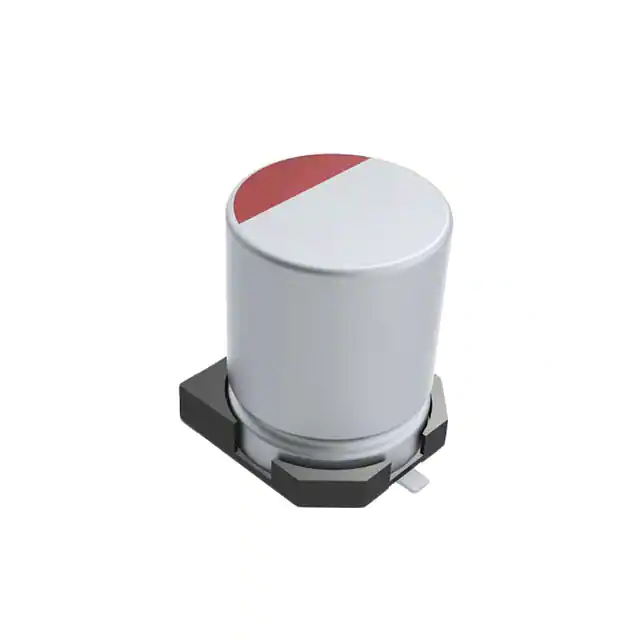
Surface Mount Solid Polymer Aluminum Capacitors
A767 105°C
Overview
Applications
KEMET’s A767 Surface Mount Solid Polymer Aluminum
Capacitors offer longer life and greater stability across a
wide range of temperatures. This highly conductive solid
polymer electrolyte eliminates the risk of drying out and due
to its low ESR properties, is able to withstand higher ripple
currents during normal operation. This series is ideally
suited for industrial and commercial applications. For
voltages ≥ 25 V, individual part numbers can be AEC-Q200
qualified on request. See Part Number system to order.
Typical applications include industrial power supplies,
switch power supplies, and industrial control systems.
For voltages ≥ 25 V, this series is used for
automotive infotainment.
Benefits
• Surface mount form factor
• Ultra low impedance
• High ripple current
• High voltage
• 105°C/2,000 hours
• RoHS compliant
• Halogen-free
Click image above for interactive 3D content
Open PDF in Adobe Reader for full functionality
Part Number System
A
767
EB
226
M
1H
LA
E
050
Capacitor
Class
Series
Size Code
Capacitance
Code (pF)
Tolerance
Rated Voltage
(VDC)
Packaging
Electrical
Parameters
ESR
Surface
Mount Solid
Polymer
Aluminum
Capacitors
105°C
2,000 hours
High Voltage
See
Dimension
Table
LA =
Tape & Reel
E = Standard/ESR
S = Automotive
A = Aluminum
First two
digits
represent
significant
figures for
capacitance
values. Last
digit specifies
the number
of zeros to be
added.
M = ±20%
35 = 1V
50 = 1H
63 = 1J
80 = 1K
100 = 2A
AEC-Q200
available on
≥ 25 V
Last 3 digits
represent
significant
figures for
ESR values.
(mΩ)
One world. One KEMET
© KEMET Electronics Corporation • KEMET Tower • One East Broward Boulevard�
Fort Lauderdale, FL 33301 USA • 954-766-2800 • www.kemet.com
A4071_A767 • 1/28/2020
1
�Surface Mount Solid Polymer Aluminum Capacitors
A767 105°C
Ordering Options Table
Packaging Type
Packaging Code
Standard Packaging Options
Tape & Reel
LA
Contact KEMET for other Lead and Packaging options
Dimensions – Millimeters
D
H
W
P
R
L
C
0.2 Maximum
Size
Code
EB
KN
KS
MU
D
L
W
H
C
R
Nominal Tolerance Nominal Tolerance Nominal Tolerance Nominal Tolerance Nominal Tolerance
6.3
8
8
10
±0.5
±0.5
±0.5
±0.5
5.7
9.7
12.0
12.6
±0.3
±0.3
±0.3
±0.3
6.6
8.3
8.3
10.3
±0.2
±0.2
±0.2
±0.2
© KEMET Electronics Corporation • KEMET Tower • One East Broward Boulevard�
Fort Lauderdale, FL 33301 USA • 954-766-2800 • www.kemet.com
6.6
8.3
8.3
10.3
±0.2
±0.2
±0.2
±0.2
7.3
9.0
9.0
11.0
±0.2
±0.2
±0.2
±0.2
P
Nominal
0.5 – 0.9
0.8 – 1.1
0.8 – 1.1
0.8 – 1.1
A4071_A767 • 1/28/2020
2.0
3.1
3.2
4.6
2
�Surface Mount Solid Polymer Aluminum Capacitors
A767 105°C
Environmental Compliance
As an environmentally conscious company, KEMET is working continuously with improvements concerning the environmental
effects of both our capacitors and their production. In Europe (RoHS Directive) and in some other geographical areas like
China, legislation has been put in place to prevent the use of some hazardous materials, such as lead (Pb), in electronic
equipment. All products in this catalog are produced to help our customers' obligations to guarantee their products and fulfill
these legislative requirements. The only material of concern in our products has been lead (Pb), which has been removed
from all designs to fulfill the requirement of containing less than 0.1% of lead in any homogeneous material. KEMET will
closely follow any changes in legislation worldwide and make any necessary changes in its products, whenever needed.
Some customer segments such as medical, military and automotive electronics may still require the use of lead in electrode
coatings. To clarify the situation and distinguish products from each other, a special symbol is used on the packaging labels
for RoHS compatible capacitors.
Due to customer requirements, there may appear additional markings such as lead-free (LF) or lead-free wires (LFW) on the
label.
Performance Characteristics
Item
Performance Characteristics
Capacitance Range
18 – 220 µF
Rated Voltage
35 – 100 VDC
Operating Temperature
−55°C to +105°C
Capacitance Tolerance
±20% at 120 Hz/20°C
Life Test
Leakage Current
2,000 hours (see conditions in Test Method & Performance)
≤ Specified Value
C = Rated capacitance (µF), V = Rated voltage (VDC), Voltage applied for 2 minutes at 20°C.
Compensation Factor of Ripple Current (RC) vs. Frequency
Frequency
Coefficient
120 Hz ≤ f < 1 kHz
1 kHz ≤ f < 10 kHz
0.05
0.30
© KEMET Electronics Corporation • KEMET Tower • One East Broward Boulevard�
Fort Lauderdale, FL 33301 USA • 954-766-2800 • www.kemet.com
10 kHz ≤ f < 100 kHz 100 kHz ≤ f < 500 kHz
0.70
1.00
A4071_A767 • 1/28/2020
3
�Surface Mount Solid Polymer Aluminum Capacitors
A767 105°C
Test Method & Performance
Conditions
Load Life Test
Shelf Life Test
Temperature
105°C
105°C
Test Duration
2,000 hours
168 hours
Ripple Current
No ripple current applied
No ripple current applied
The sum of DC voltage and the peak AC voltage must not exceed the
rated voltage of the capacitor
No voltage applied
Voltage
Performance
The following specifications will be satisfied when the capacitor is restored to 20°C.
Capacitance Change
Within ±20% of the initial value
Dissipation Factor
Does not exceed 150% of the specified value
ESR
Does not exceed 150% of the specified value
Leakage Current
Does not exceed specified value
The following specifications will be satisfied when the capacitor is restored to 20°C
after application of rated voltage for 1,000 hours at 60°C, 90%~95% RH.
Damp Heat
Capacitance Change
Within ±20% of the initial value
Dissipation Factor
Does not exceed 150% of the specified value
ESR
Does not exceed 150% of the specified value
Leakage Current
Surge Voltage
(Rated Voltage x 1.15 (V))
Capacitance Change
Does not exceed specified value
The following specifications will be satisfied when the capacitor is subjected to 1,000
cycles each consisting of charge with the surge voltages specified at 105°C for 30
seconds through a protective resistor (Rc = 1 kΩ) and discharge for
5 minutes 30 seconds.
Within ±20% of the initial value
Dissipation Factor
Does not exceed 150% of the specified value
ESR
Does not exceed 150% of the specified value
Leakage Current
Resistance to Soldering
Heat
Capacitance Change
Does not exceed specified value
Measurement for solder temperature profile at capacitor top and terminal.
Within ±10% of the initial value
Dissipation Factor
Does not exceed 130% of the specified value
ESR
Does not exceed 130% of the specified value
Leakage Current
Does not exceed specified value
© KEMET Electronics Corporation • KEMET Tower • One East Broward Boulevard�
Fort Lauderdale, FL 33301 USA • 954-766-2800 • www.kemet.com
A4071_A767 • 1/28/2020
4
�Surface Mount Solid Polymer Aluminum Capacitors
A767 105°C
Shelf Life & Re-Ageing
Shelf Life
Solderability is 12 months
The capacitance, ESR and impedance of a capacitor will not change significantly after extended storage periods, however the
leakage current will slowly increase.
• This series should not be stored in high temperatures or where there is a high level of humidity.
• The suitable storage condition is +5 to +35°C and less than 75% in relative humidity.
• Do not store in damp conditions such as water, saltwater spray or oil spray.
• Do not store in an environment full of hazardous gas (hydrogen sulphide, sulphurous acid gas, nitrous acid, chlorine gas,
ammonium, etc.)
•Do not store under exposure to ozone, ultraviolet rays or radiation.
If a capacitor has been stored for more than 12 months under these conditions and it shows increased leakage current,
then a treatment by voltage application is recommended. The Capacitor should be soldered within 7 days after unpack.
MSL Rating 2A
Re-age Procedure
Apply the rated DC voltage to the capacitor at 105°C for a period of 120 minutes through a 1 kΩ series resistor.
.
© KEMET Electronics Corporation • KEMET Tower • One East Broward Boulevard�
Fort Lauderdale, FL 33301 USA • 954-766-2800 • www.kemet.com
A4071_A767 • 1/28/2020
5
�Surface Mount Solid Polymer Aluminum Capacitors
A767 105°C
Table 1 – Ratings & Part Number Reference
Rated
Case Size
Capacitance
D x L (mm)
120 Hz 20°C (µF)
ESR
100 kHz
20°C (mΩ)
RC
100 kHz
105°C
(mA)
LC
20°C
2 Minutes
(µA)
KEMET
Part Number
VDC
VDC Surge
Voltage
35
35
35
35
35
35
35
35
35
35
35
50
50
50
50
50
50
50
63
63
63
63
63
80
80
80
100
100
40.2
40.2
40.2
40.2
40.2
40.2
40.2
40.2
40.2
40.2
40.2
57.5
57.5
57.5
57.5
57.5
57.5
57.5
72
72
72
72
72
92
92
92
115
115
10
18
22
33
47
56
82
100
150
180
220
18
22
33
47
56
82
100
22
33
47
68
100
22
33
47
10
22
6.3 x 5.7
6.3 x 5.7
6.3 x 5.7
8 x 9.7
8 x 9.7
8 x 9.7
8 x 9.7
10 x 12.6
10 x 12.6
10 x 12.6
10 x 12.6
8 x 9.7
8 x 9.7
8 x 9.7
8 x 9.7
8 x 9.7
10 x 12.6
10 x 12.6
8 x 9.7
8 x 9.7
8 x 12
10 x 12.6
10 x 12.6
8 x 9.7
8 x 12
10 x 12.6
8 x 12
10 x 12.6
85
85
50
31
31
31
31
29
28
28
28
50
50
45
29
29
27
27
45
42
36
30
28
45
45
40
45
38
800
800
1,300
1,900
1,900
1,900
3,600
2,500
2,600
2,600
2,600
1,300
1,500
1,800
3,300
2,800
3,300
2,500
1,800
1,950
2,200
2,450
2,550
2,100
2,100
2,500
1,700
2,250
300
300
300
300
329
392
574
700
1,050
1,260
1,540
300
300
330
470
560
820
1,000
300
415
592
856
1,260
352
528
752
300
440
A767EB106M1VLA(1)085
A767EB186M1VLA(1)085
A767EB226M1VLA(1)050
A767KN336M1VLA(1)031
A767KN476M1VLA(1)031
A767KN566M1VLA(1)031
A767KN826M1VLA(1)031
A767MU107M1VLA(1)029
A767MU157M1VLA(1)028
A767MU187M1VLA(1)028
A767MU227M1VLA(1)028
A767KN186M1HLA(1)050
A767KN226M1HLA(1)050
A767KN336M1HLA(1)045
A767KN476M1HLA(1)029
A767KN566M1HLA(1)029
A767MU826M1HLA(1)027
A767MU107M1HLA(1)027
A767KN226M1JLA(1)045
A767KN336M1JLA(1)042
A767KS476M1JLA(1)036
A767MU686M1JLA(1)030
A767MU107M1JLA(1)028
A767KN226M1KLA(1)045
A767KS336M1KLA(1)045
A767MU476M1KLA(1)040
A767KS106M2ALA(1)045
A767MU226M2ALA(1)038
VDC
VDC Surge
Rated Capacitance
Case Size
ESR
RC
LC
Part Number
(1)Electrical Parameters code. See Part Number System for available options.
© KEMET Electronics Corporation • KEMET Tower • One East Broward Boulevard�
Fort Lauderdale, FL 33301 USA • 954-766-2800 • www.kemet.com
A4071_A767 • 1/28/2020
6
�Surface Mount Solid Polymer Aluminum Capacitors
A767 105°C
Installing
Solid Polymer Aluminum Capacitors are prone to a change in leakage current due to thermal stress during soldering. The
leakage current may increase after soldering or reflow soldering. Therefore, verify the suitability for use in circuits sensitive
to leakage current.
A general principle is that lower temperature operation results in a longer, useful life of the capacitor. For this reason, it
should be ensured that electrolytic capacitors are placed away from heat-emitting components. Adequate space should be
allowed between components for cooling air to circulate, especially when high ripple current loads are applied. In any case,
the maximum rated temperature must not be exceeded.
• Do not deform the case of capacitors or use capacitors with a deformed case.
• Verify that the connections of the capacitors are able to insert on the board without excessive mechanical force.
Excessive force during insertion, as well as after soldering may cause terminal damage and affect the electrical
performance.
• Ensure electrical insulation between the capacitor case, negative terminal, positive terminal and PCB.
• If the capacitors require mounting through additional means, the recommended mounting accessories shall be used.
• Verify the correct polarization of the capacitor on the board.
KEMET recommends, to ensure that the voltage across each capacitor does not exceed its rated voltage.
Temperature Stability Characteristics
table characteristics in a very low temperature range allows for less circuits in the design.
Due to a solid polymer electrolyte, Solid Polymer Aluminum Capacitors feature higher conductivity. This results in a lower
ESR which, coupled with high capacitance allows an aluminum polymer capacitor to replace several standard electrolytic
capacitors, reducing the number of components and maximizing board space.
The ESR of polymer capacitors is nearly constant within its operating temperature range, while the ESR of a standard
electrolytic capacitor noticeably changes with temperature.
Temperature Stability Characteristics
1,000
Aluminum Electrolytic
Conductive Polymer Electrolytic
ESR (Ω)
100
10
1
0.1
0.01
−55
−20
0
20
Temperature (°C)
70
105
125
© KEMET Electronics Corporation • KEMET Tower • One East Broward Boulevard�
Fort Lauderdale, FL 33301 USA • 954-766-2800 • www.kemet.com
A4071_A767 • 1/28/2020
7
�Surface Mount Solid Polymer Aluminum Capacitors
A767 105°C
Expected Life Calculation Chart
Expected life depends on operating temperature according to the following formula:
L = Lo x 10(To-T)/20
Where:
L: Expected life
Lo: Life at maximum permissible operating temperature with rated operating voltage applied (hours)
T: Actual operating temperature
To: Maximum permissible operating temperature
Actual Operating Temperature (ºC)
Expected Life Calculation Chart
105ºC
85ºC
65ºC
2,000
20,000
200,000
Expected Life (hours)
The effect of derating temperature can be seen in this graph.
In this example, the life expectancy of a 2,000 hour polymer capacitor is significantly greater than that of a 2,000 hour
standard electrolytic capacitor.
Capacitor Life (H)
50,000
100,000
150,000
200,000
Temperature (ºC)
105
100
95
90
Aluminum Electrolytic
Conductive Polymer Electrolytic
85
80
75
70
65
© KEMET Electronics Corporation • KEMET Tower • One East Broward Boulevard�
Fort Lauderdale, FL 33301 USA • 954-766-2800 • www.kemet.com
A4071_A767 • 1/28/2020
8
�Surface Mount Solid Polymer Aluminum Capacitors
A767 105°C
Stability of ESR across Frequency Range
Due to a solid polymer electrolyte, the ESR curve of a solid polymer aluminum capacitor, is lower and more stable than that
of a standard electrolytic capacitor.
Stable ESR Values across Frequency
100
Aluminum Electrolytic
Conductive Polymer Electrolytic
ESR
10
1
0.1
0.01
0
10K
100K
Frequency (Hz)
1M
10M
High Resistance to Ripple Current
As a result of a lower ESR, solid polymer aluminum capacitors are able to withstand higher ripple currents during
normal operation.
Allowable Ripple Current (100 kHz 105°C)
Ripple Current (Arms)
4
3.5
3
Aluminum Electrolytic
Conductive Polymer Electrolytic
2.5
2
1.5
1
0.5
0
33 µF/16 V
47 µF/16 V
100 µF/16 V
220 µF/16 V
© KEMET Electronics Corporation • KEMET Tower • One East Broward Boulevard�
Fort Lauderdale, FL 33301 USA • 954-766-2800 • www.kemet.com
A4071_A767 • 1/28/2020
9
�Surface Mount Solid Polymer Aluminum Capacitors
A767 105°C
Landing Pad – Millimeters
C
B
A
D
A
B
C
5
6.3
8
10
1.4
1.9
3.1
4.5
3
3.5
4.2
4.4
1.6
1.6
2.2
2.2
B
Marking
Trademark
Rated
Voltage
Date Code*
1 Digits = Rated Voltage
st
Letter = Year Code
Series
Date Code*
(Last 3 Digits)
Capacitance
© KEMET Electronics Corporation • KEMET Tower • One East Broward Boulevard�
Fort Lauderdale, FL 33301 USA • 954-766-2800 • www.kemet.com
Final Digits = Week of the Year
S = 2019
01 = 1st week of the Year to
52 = 52nd week of the Year
Year Code
S
2019
T
2020
U
2021
V
2022
W
2023
X
2024
Y
2025
Z
2026
A4071_A767 • 1/28/2020
10
�Surface Mount Solid Polymer Aluminum Capacitors
A767 105°C
Construction
Aluminum Can
Lead
Terminal Tabs
Detailed Cross Section
Rubber Seal
Terminal Tab
Rubber Seal
Margin
Aluminum Can
Paper Spacer with Solid
Polymer Electrolyte
(First Layer)
Paper Spacer with Solid
Polymer Electrolyte
(Third Layer)
Anode Aluminum Foil,
Cathode Aluminum
Etched, Covered with
Foil,
Etched (Fourth
Aluminum Oxide
Layer)
(Second Layer)
© KEMET Electronics Corporation • KEMET Tower • One East Broward Boulevard�
Fort Lauderdale, FL 33301 USA • 954-766-2800 • www.kemet.com
Lead (+)
Lead (−)
A4071_A767 • 1/28/2020
11
�Surface Mount Solid Polymer Aluminum Capacitors
A767 105°C
Re-Flow Soldering
The soldering conditions should be within the specified conditions below:
• Do not dip the capacitors body into the melted solder.
• Flux should only be applied to the capacitors' terminals.
• Vapour heat transfer systems are not recommended. The system should be thermal, such as infra-red radiation or hot
blast.
• Observe the soldering conditions as shown below.
• Do not exceed these limits and avoid repeated reflowing.
Time Period
Temperature (°C)
Time (seconds)
Preheating
T1
T2
Φ