C410C104K5R5TA91707200 数据手册
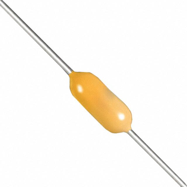
Axial Leaded Multilayer Ceramic Capacitors
Aximax, 400, Conformally Coated,
X7R Dielectric, 25 – 250 VDC (Automotive Grade)
Overview
KEMET’s Aximax conformally coated axial leaded ceramic
capacitors in X7R dielectric feature a 125°C maximum
operating temperature. The Electronics Industries
Alliance (EIA) characterizes X7R dielectric as a Class
II "temperature stable" material. Components of this
classification are fixed, ceramic dielectric capacitors suited
for bypass and decoupling applications or for frequency
discriminating circuits where Q and stability of capacitance
characteristics are not critical. X7R exhibits a predictable
change in capacitance with respect to time and voltage
and boasts a minimal change in capacitance with reference
to ambient temperature. Capacitance change is limited to
±15% from −55°C to +125°C.
These devices meets the flame test requirements outlined
in UL Standard 94V–0 and the demanding Automotive
Electronics Council's AEC–Q200 qualification requirements.
Benefits
• Axial leaded form factor
• Conformally
• Encapsulation meets flammability standard UL 94V–0
• Operating temperature range of −55°C to +125°C
• Lead (Pb)-free, RoHS and REACH compliant
Click image above for interactive 3D content
Ordering Information
C
Ceramic
410
C
Style/ Specification/
Size
Series
410
420
430
C=
Standard
Open PDF in Adobe Reader for full functionality
105
K
3
R
5
T
A
9170
Capacitance
Code (pF)
Capacitance
Tolerance1
Voltage
Dielectric
Design
Lead
Finish
Failure
Rate
Packaging/Grade
(C-Spec)
R=
X7R
5=
Multilayer
T=
100%
Matte Sn
A=
N/A
Automotive Grade
First two digits
represent
significant
figures. Third
digit specifies
number of
zeros.
J = ±5%
K = ±10%
M = ±20%
3 = 25
5 = 50
1 = 100
2 = 200
A = 250
9170 = Bulk Auto Grade
9170 7200 = T & R 12"
Auto Grade
9170 7293 = Ammo Pack
Auto Grade
Additional capacitance Tolerance offerings may be available. Contact KEMET for details.
For Overmolding applications please contact your KEMET representative.
1
One world. One KEMET
© KEMET Electronics Corporation • KEMET Tower • One East Broward Boulevard�
Fort Lauderdale, FL 33301 USA • 954-766-2800 • www.kemet.com
C1044_AXIMAX_X7R_AUTO • 10/28/2019
1
�Axial Leaded Multilayer Ceramic Capacitors
Aximax, 400, Conformally Coated, X7R Dielectric, 25 – 250 VDC (Automotive Grade)
Benefits cont.
• X7R Temperature stable dielectric
• DC voltage ratings of 25 V, 50 V, 100 V, 200 V, and 250 V
• Capacitance offerings ranging from 10 pF to 4.7 μF
• Available capacitance tolerances of ±5%, ±10% and ±20%
• Non-polar device, minimizing installation concerns
• 100% pure matte tin-plated lead finish allowing for
excellent solderability
• Automotive (AEC–Q200) grade.
Applications
Typical applications include decoupling, bypass, filtering and transient voltage suppression.
Application Notes
These devices are not recommended for use in overmold applications and/or processes.
Dimensions – Inches (Millimeters)
LL
L
D
LD
Series
0.015 (0.38)
Maximum
Style/Size
L
Length
Maximum
D
Diameter
Maximum
C41X
410
0.170 (4.32)
0.095 (2.41)
C42X
C43X
420
430
0.200 (5.08)
0.240 (6.10)
0.100 (2.54)
0.150 (3.81)
LD
Lead Diameter
LL
Lead Length
Minimum
0.020 +0.001/−0.003
(0.51 +0.025/−0.076)
1.0
(25.4)
Qualification/Certification
Automotive Grade products meet or exceed the requirements outlined by the Automotive Electronics Council. Details
regarding test methods and conditions are referenced in document AEC–Q200, Stress Test Qualification for Passive
Components. For additional information regarding the Automotive Electronics Council and AEC–Q200, please visit their
website at www.aecouncil.com.
© KEMET Electronics Corporation • KEMET Tower • One East Broward Boulevard�
Fort Lauderdale, FL 33301 USA • 954-766-2800 • www.kemet.com
C1044_AXIMAX_X7R_AUTO • 10/28/2019
2
�Axial Leaded Multilayer Ceramic Capacitors
Aximax, 400, Conformally Coated, X7R Dielectric, 25 – 250 VDC (Automotive Grade)
Automotive C-Spec Information
KEMET Automotive Grade products meet or exceed the requirements outlined by the Automotive Electronics Council.
Details regarding test methods and conditions are referenced in document AEC–Q200, Stress Test Qualification for Passive
Components. These products are supported by a Product Change Notification (PCN) and Production Part Approval Process
warrant (PPAP).
Automotive products offered through our distribution channel have been assigned an inclusive ordering code C-Spec, “9170.”
This C-Spec was developed in order to better serve small and medium sized companies that prefer an automotive grade
component without the requirement to submit a customer Source Controlled Drawing (SCD) or specification for review by a
KEMET engineering specialist. This C-Spec is therefore not intended for use by KEMET’s OEM Automotive customers and are
not granted the same “privileges” as other automotive C-Specs. Customer PCN approval and PPAP request levels are limited
(see details below).
Product Change Notification (PCN)
The KEMET Product Change Notification system is used to communicate primarily the following types of changes:
• Product/process changes that affect product form, fit, function, and/or reliability
• Changes in manufacturing site
• Product obsolescence
Process/Product change
Obsolescence*
Days prior to
implementation
KEMET assigned
Yes (with approval and sign off)
Yes
180 days Minimum
9170
Yes (without approval)
Yes
90 days Minimum
1
1
Customer Notification due to:
KEMET Automotive
C-Spec
KEMET assigned C-Specs require the submittal of a customer SCD or customer specification for review. For additional information contact KEMET.
Production Part Approval Process (PPAP)
The purpose of the Production Part Approval Process is:
• To ensure that supplier can meet the manufacturability and quality requirements for the purchased parts.
• To provide the evidence that all customer engineering design record and specification requirements are properly
understood and fulfilled by the manufacturing organization.
• To demonstrate that the established manufacturing process has the potential to produce the part
PPAP (Product Part Approval Process) Level
KEMET Automotive
C-Spec
1
2
3
4
5
KEMET assigned1
●
●
●
●
●
9170
1
○
KEMET assigned C-Specs require the submittal of a customer SCD or customer specification for review. For additional information contact KEMET.
● Part Number specific PPAP available
○ Product family PPAP only
© KEMET Electronics Corporation • KEMET Tower • One East Broward Boulevard�
Fort Lauderdale, FL 33301 USA • 954-766-2800 • www.kemet.com
C1044_AXIMAX_X7R_AUTO • 10/28/2019
3
�Axial Leaded Multilayer Ceramic Capacitors
Aximax, 400, Conformally Coated, X7R Dielectric, 25 – 250 VDC (Automotive Grade)
Environmental Compliance
Lead (Pb)-free, REACH and RoHS compliant without exemptions when ordered with a 100% tin (Sn) wire lead finish.
1
Series
Termination
Finish
(Wire Lead)
RoHS
Compliant
RoHS
Exemption
Code
REACH
Compliant1
Halogen
Free
400 (C4XX)
100% Matte Sn
Yes
n/a
Yes
Yes
REACH compliance indicates product does not contain Substance/s of Very High Concern (SVHC)
Electrical Parameters/Characteristics
Item
Parameters/Characteristics
Operating Temperature Range
−55°C to +125°C
Capacitance Change with Reference to
+25°C and 0 VDC Applied (TCC)
±15%
Aging Rate (Max % Cap Loss/Decade Hour)
3.0%
Dielectric Withstanding Voltage
Dissipation Factor (DF) Maximum Limit at 25ºC
Insulation Resistance (IR) Limit at 25°C
250% of rated voltage
(5±1 seconds and charge/discharge not exceeding 50 mA)
3.5%(25 V) and 2.5%(50 V to 250 V)
See Insulation Resistance Limit Table
(Rated voltage applied for 120±5 seconds at 25°C)
Regarding aging rate: Capacitance measurements (including tolerance) are indexed to a referee time of 1,000 hours.
To obtain IR limit, divide MΩ-µF value by the capacitance and compare to GΩ limit. Select the lower of the two limits.
Capacitance and dissipation factor (DF) measured under the following conditions:
1 kHz ±50 Hz and 1.0 ±0.2 Vrms if capacitance ≤ 10 µF
120 Hz ±10 Hz and 0.5 ±0.1 Vrms if capacitance > 10 µF
Note: When measuring capacitance it is important to ensure the set voltage level is held constant. The HP4284 and Agilent E4980 have a feature known
as Automatic Level Control (ALC). The ALC feature should be switched to "ON."
Post Environmental Limits
High Temperature Life, Biased Humidity, Moisture Resistance
Style/Size
Rated
DC Voltage
Capacitance
Value
Dissipation Factor
(Maximum %)
Capacitance
Shift
Insulation
Resistance
All
25
> 25
All
5.0
3.0
± 20%
10% of Initial Limit
Insulation Resistance Limit Table
Style/Size
1,000 Megohm
Microfarads or 100 GΩ
500 Megohm
Microfarads or 10 GΩ
410
420
430
< 0.15µF
< 0.68µF
< 0.47µF
≥ 0.15µF
≥ 0.68µF
≥ 0.47µF
© KEMET Electronics Corporation • KEMET Tower • One East Broward Boulevard�
Fort Lauderdale, FL 33301 USA • 954-766-2800 • www.kemet.com
C1044_AXIMAX_X7R_AUTO • 10/28/2019
4
�Axial Leaded Multilayer Ceramic Capacitors
Aximax, 400, Conformally Coated, X7R Dielectric, 25 – 250 VDC (Automotive Grade)
Table 1A – C410 Style/Size (0.100" Diameter x 0.170" L), Capacitance Range Waterfall
C410 Style/Size (0.100" Diameter x 0.170" L )
Rated Voltage (VDC)
25
50
100
200
250
Voltage Code
3
5
1
2
A
Capacitance
10pF
12pF
15pF
18pF
22pF
27pF
33pF
39pF
47pF
56pF
68pF
82pF
100pF
120pF
150pF
180pF
220pF
270pF
330pF
390pF
470pF
560pF
680pF
820pF
1000pF
1200pF
1500pF
1800pF
2200pF
2700pF
3300pF
3900pF
4700pF
5600pF
6800pF
8200pF
0.01µF
0.012µF
0.015µF
0.018µF
0.022µF
0.027µF
0.033µF
0.039µF
0.047µF
0.056µF
0.068µF
0.082µF
0.1µF
0.12µF
0.15µF
0.18µF
0.22µF
0.27µF
0.33µF
0.39µF
0.47µF
Capacitance
Tolerance
Capacitance Code (Available Capacitance)
100
120
150
180
220
270
330
390
470
560
680
820
101
121
151
181
221
271
331
391
471
561
681
821
102
122
152
182
222
272
332
392
472
562
682
822
103
123
153
183
223
273
333
393
473
563
683
823
104
124
154
184
224
274
334
394
474
100
120
150
180
220
270
330
390
470
560
680
820
101
121
151
181
221
271
331
391
471
561
681
821
102
122
152
182
222
272
332
392
472
562
682
822
103
123
153
183
223
273
333
393
473
563
683
823
104
124
154
184
224
274
334
394
474
100
120
150
180
220
270
330
390
470
560
680
820
101
121
151
181
221
271
331
391
471
561
681
821
102
122
152
182
222
272
332
392
472
562
682
822
103
123
153
183
223
273
333
393
473
563
683
823
104
124
154
184
224
100
120
150
180
220
270
330
390
470
560
680
820
101
121
151
181
221
271
331
391
471
561
681
821
102
122
152
182
222
272
332
392
472
562
682
822
103
123
153
183
223
273
333
393
473
563
100
120
150
180
220
270
330
390
470
560
680
820
101
121
151
181
221
271
331
391
471
561
681
821
102
122
152
182
222
272
332
392
472
562
682
822
103
123
153
183
223
Rated Voltage (VDC)
25
50
100
200
250
Voltage Code
3
5
1
2
A
J = ±5%
K = ±10%
M = ±20%
© KEMET Electronics Corporation • KEMET Tower • One East Broward Boulevard�
Fort Lauderdale, FL 33301 USA • 954-766-2800 • www.kemet.com
C1044_AXIMAX_X7R_AUTO • 10/28/2019
5
�Axial Leaded Multilayer Ceramic Capacitors
Aximax, 400, Conformally Coated, X7R Dielectric, 25 – 250 VDC (Automotive Grade)
Table 1A – C410 Style/Size (0.100" Diameter x 0.170" L), Capacitance Range Waterfall cont'.
C410 Style/Size (0.100" Diameter x 0.170" L )
Rated Voltage (VDC)
25
50
100
200
250
Voltage Code
3
5
1
2
A
Capacitance
0.56µF
0.68µF
0.82µF
1.0µF
Capacitance
Tolerance
Capacitance Code (Available Capacitance)
564
684
824
105
564
684
Rated Voltage (VDC)
25
50
100
200
250
Voltage Code
3
5
1
2
A
J = ±5%
K = ±10%
M = ±20%
Table 1B – C420 Style/Size (0.100" Diameter x 0.260" L), Capacitance Range Waterfall
C420 Style/Size (0.100" Diameter x 0.260" L )
Rated Voltage (VDC)
25
50
100
200
250
Voltage Code
3
5
1
2
A
Capacitance
Capacitance
Tolerance
0.027µF
0.033µF
0.039µF
0.047µF
0.056µF
0.068µF
0.082µF
0.1µF
0.12µF
0.15µF
0.18µF
0.22µF
0.27µF
0.33µF
0.39µF
0.47µF
0.56µF
0.68µF
0.82µF
1.0µF
Capacitance Code (Available Capacitance)
273
333
393
473
563
683
823
104
124
154
184
224
274
334
394
474
564
684
824
105
273
333
393
473
563
683
823
104
124
154
184
224
274
334
394
474
564
684
824
105
273
333
393
473
563
683
823
104
124
154
184
224
274
273
333
393
473
563
683
823
104
273
333
393
473
563
683
823
104
Rated Voltage (VDC)
25
50
100
200
250
Voltage Code
3
5
1
2
A
J = ±5%
K = ±10%
M = ±20%
© KEMET Electronics Corporation • KEMET Tower • One East Broward Boulevard�
Fort Lauderdale, FL 33301 USA • 954-766-2800 • www.kemet.com
C1044_AXIMAX_X7R_AUTO • 10/28/2019
6
�Axial Leaded Multilayer Ceramic Capacitors
Aximax, 400, Conformally Coated, X7R Dielectric, 25 – 250 VDC (Automotive Grade)
Table 1C – C430 Style/Size (0.150" Diameter x 0.290" L), Capacitance Range Waterfall
C430 Style/Size (0.150" Diameter x 0.290" L )
Rated Voltage (VDC)
25
50
100
200
Voltage Code
3
5
1
2
Capacitance
Capacitance
Tolerance
0.12µF
0.15µF
0.18µF
0.22µF
0.27µF
0.33µF
0.39µF
0.47µF
0.56µF
0.68µF
0.82µF
1.0µF
1.2µF
1.5µF
1.8µF
2.0µF
2.2µF
2.7µF
3.3µF
3.9µF
4.7µF
Capacitance Code (Available Capacitance)
124
154
184
224
274
334
394
474
564
684
824
105
125
155
185
205
225
275
335
395
475
124
154
184
224
274
334
394
474
564
684
824
105
125
155
185
205
225
124
154
184
224
274
334
394
474
124
154
Rated Voltage (VDC)
25
50
100
200
Voltage Code
3
5
1
2
J = ±5%
K = ±10%
M = ±20%
© KEMET Electronics Corporation • KEMET Tower • One East Broward Boulevard�
Fort Lauderdale, FL 33301 USA • 954-766-2800 • www.kemet.com
C1044_AXIMAX_X7R_AUTO • 10/28/2019
7
�Axial Leaded Multilayer Ceramic Capacitors
Aximax, 400, Conformally Coated, X7R Dielectric, 25 – 250 VDC (Automotive Grade)
Soldering Process
Recommended Soldering Methods:
• Solder Wave
• Hand Soldering (Manual)
Recommended Soldering Profile:
• Optimum Wave Solder Profile
Solder Wave Peak
Temperature 260ºC
Entrance to Solder Wave
Degrees – Cº
Flux Zone
250
225
200
175
150
125
100
75
50
25
Exit from Solder Wave
(Time in Wave – 2 to 4 Seconds)
Preheat Zone
Hot Air Debridging
Exit from
Solder
Machine
80ºC
to 120ºC
Entrance
to Solder
Machine
Free
Air
Cool
Bottom Side
Temperature
Range
Entrance to
In-Line Cleaner
Exit from
In-Line Cleaner
(time in cleaner
may be less)
Immersion in
Cleaning
Vapor
150ºC
Maximum
Top Side
Nominal
0
1
2
3
Time (Minutes)
4
5
6
• Hand Soldering (Manual)
Manual Solder Profile with Pre-heating
Soldering
Gradual Cooling
Gradual Preheat
60 – 120 Seconds
Recommend 2.5°C/second
Maximum 3 seconds
Delta T < = 120ºC
© KEMET Electronics Corporation • KEMET Tower • One East Broward Boulevard�
Fort Lauderdale, FL 33301 USA • 954-766-2800 • www.kemet.com
C1044_AXIMAX_X7R_AUTO • 10/28/2019
8
�Axial Leaded Multilayer Ceramic Capacitors
Aximax, 400, Conformally Coated, X7R Dielectric, 25 – 250 VDC (Automotive Grade)
Storage & Handling
The un-mounted storage life of a leaded ceramic capacitor is dependent upon storage and atmospheric conditions as
well as packaging materials. While the ceramic chips enveloped under the epoxy coating themselves are quite robust
in most environments, solderability of the wire lead on the final epoxy-coated product will be degraded by exposure to
high temperatures, high humidity, corrosive atmospheres, and long term storage. In addition, packaging materials will be
degraded by high temperature and exposure to direct sunlight–reels may soften or warp, and tape peel force may increase.
KEMET recommends storing the un-mounted capacitors in their original packaging, in a location away from direct sunlight,
and where the temperature and relative humidity do not exceed 40 degrees centigrade and 70% respectively. For optimum
solderability, capacitor stock should be used promptly, preferably within 18 months of receipt. For applications requiring
pre-tinning of components, storage life may be extended if solderability is verified. Before cleaning, bonding or molding these
devices, it is important to verify that your process does not affect product quality and performance. KEMET recommends
testing and evaluating the performance of a cleaned, bonded or molded product prior to implementing and/or qualifying any
of these processes.
© KEMET Electronics Corporation • KEMET Tower • One East Broward Boulevard�
Fort Lauderdale, FL 33301 USA • 954-766-2800 • www.kemet.com
C1044_AXIMAX_X7R_AUTO • 10/28/2019
9
�Axial Leaded Multilayer Ceramic Capacitors
Aximax, 400, Conformally Coated, X7R Dielectric, 25 – 250 VDC (Automotive Grade)
Construction
Finish Layer
(Sn)
Finish Layer
(Sn)
Epoxy
Barrier Layer
Encapsulation
(Ni)
External Electrode
(Cu)
Detailed Cross Section
Dielectric Material
(BaTiO3)
Barrier Layer
(Ni)
External Electrode
(Cu)
Inner Electrodes
(Ni)
Epoxy
Encapsulation
Lead Attach Solder
(Sn95/Sb5)
Lead Wire
Std
Core Metal
Barrier Layer
Steel
Ni
100%
Finish Layer Matte Sn
Inner Electrodes
(Ni)
Dielectric
Material (BaTiO3)
Inner Electrodes
(Ni)
Marking
KEMET
Trademark
Rated
Capacitance
1
Rated Working
DC Voltage
Dielectric Code
K3R
475K
1520
Capacitance
Tolerance
15
20
Manufacturing Year:
15 = 2015
Manufacturing Week:
20 = Week 20
(of mfg. calendar year)
Date Code1
(Available as
an option only)
To properly request the inclusion of the date code in the marking, ordering code please contact your KEMET representative.
Packaging Quantities
Standard
Style/Size
Bulk Quantity
410
300/Box
420
300/Box
430
200/Box
Ammo Pack
Quantity
Maximum
Reel Quantity
Maximum
(12" Reel)
4,000
5,000
2,000
2,500
© KEMET Electronics Corporation • KEMET Tower • One East Broward Boulevard�
Fort Lauderdale, FL 33301 USA • 954-766-2800 • www.kemet.com
C1044_AXIMAX_X7R_AUTO • 10/28/2019
10
�Axial Leaded Multilayer Ceramic Capacitors
Aximax, 400, Conformally Coated, X7R Dielectric, 25 – 250 VDC (Automotive Grade)
Tape & Reel Packaging Information
KEMET offers standard reeling of molded and conformally
coated axial leaded ceramic capacitors for automatic insertion
or lead forming machines in accordance with EIA standard
296. KEMET’s internal specifi cation four-digit suffi x, 7200, is
placed at the end of the part number to designate tape and reel
packaging, e.g., C410C104Z5U5CA7200.
Paper (50 lb.) test minimum is inserted between the layers
of capacitors wound on reels for component pitch ≤ 0.400".
Capacitor lead length may extend only a maximum of .0625"
(1.59 mm) beyond the tapes’ edges. Capacitors are centered in
a row between the two tapes and will deviate only ± 0.031" (0.79
mm) from the row center. A minimum of 36" (91.5 cm) leader
tape is provided at each fi nished length of taped components.
Universal splicing clips are used to connect the tape.
Table 3 – Ceramic Axial Tape and Reel Dimensions
Metric will govern
Dimensions — Millimeters (Inches)
Axial Capacitor
Body Diameter
0.0 to 5.0
(0.0 to 0.197)
A
±0.5 (0.020)
B
±1.5 (0.059)*
5.0 (0.197)
52.4 (2.062)
Symbol Reference Table
A
B
Component Pitch
Inside Tape Spacing
* Inside tape spacing dimension (B) is determined by the body diameter of the capacitor.
© KEMET Electronics Corporation • KEMET Tower • One East Broward Boulevard�
Fort Lauderdale, FL 33301 USA • 954-766-2800 • www.kemet.com
C1044_AXIMAX_X7R_AUTO • 10/28/2019
11
�Axial Leaded Multilayer Ceramic Capacitors
Aximax, 400, Conformally Coated, X7R Dielectric, 25 – 250 VDC (Automotive Grade)
KEMET Electronics Corporation Sales Offices
For a complete list of our global sales offi ces, please visit www.kemet.com/sales.
Disclaimer
All product specifi cations, statements, information and data (collectively, the “Information”) in this datasheet are subject to change. The customer is responsible for
checking and verifying the extent to which the Information contained in this publication is applicable to an order at the time the order is placed. All Information given
herein is believed to be accurate and reliable, but it is presented without guarantee, warranty, or responsibility of any kind, expressed or implied.
Statements of suitability for certain applications are based on KEMET Electronics Corporation’s (“KEMET”) knowledge of typical operating conditions for such
applications, but are not intended to constitute – and KEMET specifi cally disclaims – any warranty concerning suitability for a specifi c customer application or use.
The Information is intended for use only by customers who have the requisite experience and capability to determine the correct products for their application. Any
technical advice inferred from this Information or otherwise provided by KEMET with reference to the use of KEMET’s products is given gratis, and KEMET assumes
no obligation or liability for the advice given or results obtained.
Although KEMET designs and manufactures its products to the most stringent quality and safety standards, given the current state of the art, isolated component
failures may still occur. Accordingly, customer applications which require a high degree of reliability or safety should employ suitable designs or other safeguards
(such as installation of protective circuitry or redundancies) in order to ensure that the failure of an electrical component does not result in a risk of personal injury
or property damage.
Although all product–related warnings, cautions and notes must be observed, the customer should not assume that all safety measures are indicted or that other
measures may not be required.
KEMET is a registered trademark of KEMET Electronics Corporation.
© KEMET Electronics Corporation • KEMET Tower • One East Broward Boulevard�
Fort Lauderdale, FL 33301 USA • 954-766-2800 • www.kemet.com
C1044_AXIMAX_X7R_AUTO • 10/28/2019
12
�


 工商网监
湘ICP备2023018690号
工商网监
湘ICP备2023018690号
