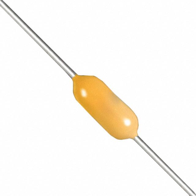
Multilayer ceramic capacitors are available in a
variety of physical sizes and configurations, including
leaded devices and surface mounted chips. Leaded
styles include molded and conformally coated parts
with axial and radial leads. However, the basic
capacitor element is similar for all styles. It is called a
chip and consists of formulated dielectric materials
which have been cast into thin layers, interspersed
with metal electrodes alternately exposed on opposite
edges of the laminated structure. The entire structure is
fired at high temperature to produce a monolithic
block which provides high capacitance values in a
small physical volume. After firing, conductive
terminations are applied to opposite ends of the chip to
make contact with the exposed electrodes.
Termination materials and methods vary depending on
the intended use.
TEMPERATURE CHARACTERISTICS
Class III: General purpose capacitors, suitable
Ceramic dielectric materials can be formulated with
a wide range of characteristics. The EIA standard for
for by-pass coupling or other applications in which
ceramic dielectric capacitors (RS-198) divides ceramic
dielectric losses, high insulation resistance and
dielectrics into the following classes:
stability of capacitance characteristics are of little or
no importance. Class III capacitors are similar to Class
II capacitors except for temperature characteristics,
Class I: Temperature compensating capacitors,
which are greater than ± 15%. Class III capacitors
suitable for resonant circuit application or other applihave the highest volumetric efficiency and poorest
cations where high Q and stability of capacitance charstability of any type.
acteristics are required. Class I capacitors have
predictable temperature coefficients and are not
effected by voltage, frequency or time. They are made
KEMET leaded ceramic capacitors are offered in
from materials which are not ferro-electric, yielding
the three most popular temperature characteristics:
superior stability but low volumetric efficiency. Class I
C0G: Class I, with a temperature coefficient of 0 ±
capacitors are the most stable type available, but have
30 ppm per degree C over an operating
the lowest volumetric efficiency.
temperature range of - 55°C to + 125°C (Also
known as “NP0”).
X7R: Class II, with a maximum capacitance
Class II: Stable capacitors, suitable for bypass
change of ± 15% over an operating temperature
or coupling applications or frequency discriminating
range of - 55°C to + 125°C.
circuits where Q and stability of capacitance charZ5U: Class III, with a maximum capacitance
acteristics are not of major importance. Class II
change of + 22% - 56% over an operating temcapacitors have temperature characteristics of ± 15%
perature range of + 10°C to + 85°C.
or less. They are made from materials which are
ferro-electric, yielding higher volumetric efficiency but
less stability. Class II capacitors are affected by
Specified electrical limits for these three temperature
temperature, voltage, frequency and time.
characteristics are shown in Table 1.
SPECIFIED ELECTRICAL LIMITS
TEMPERATURE CHARACTERISTICS
C0G
X7R
Z5U
PARAMETER
Dissipation Factor: Measured at following conditions:
C0G — 1 kHz and 1 vrms if capacitance > 1000 pF
1 MHz and 1 vrms if capacitance ≤ 1000 pF
X7R — 1 kHz and 1 vrms* or if extended cap range 0.5 vrms
Z5U — 1 kHz and 0.5 vrms
Dielectric Strength: 2.5 times rated DC voltage.
0.15%
2.5%
4.0%
Pass Subsequent IR Test
Insulation Resistance (IR): At rated DC voltage,
whichever of the two is smaller
1,000 MΩ-µF
or 100 GΩ
1,000 MΩ-µF
or 100 GΩ
1,000 MΩ-µF
or 10 GΩ
Temperature Characteristics: Range, °C
Capacitance Change without
DC voltage
-55 to +125
0 ± 30 ppm/°C
-55 to +125
±15%
+10 to +85
+22%, -56%
* 1 MHz and 1 vrms if capacitance ≤ 100 pF on military product.
Table I
© KEMET Electronics Corporation, P.O. Box 5928, Greenville, S.C. 29606, (864) 963-6300
3
Multlayer Ceramic
Capacitors
MULTILAYER CERAMIC CAPACITORS/AXIAL & RADIAL LEADED
�CERAMIC CONFORMALLY COATED/AXIAL & RADIAL
PERFORMANCE CHARACTERISTICS FOR STANDARD AND HIGH VOLTAGE
GENERAL SPECIFICATIONS
Working Voltage:
Axial (WVDC)
C0G – 50 & 100
X7R – 50 & 100
Z5U – 50 & 100
ENVIRONMENTAL
Vibration:
EIA RS-198, Method 304, Condition D (10-2000Hz; 20g)
Shock:
EIA RS-198, Method 305, Condition I (100g)
Radial (WVDC)
50, 100, 200, 500, 1k, 1.5k, 2k, 2.5k, 3k
50, 100, 200, 500, 1k, 1.5k, 2k, 2.5k, 3k
50 & 100
Life Test:
EIA RS-198, Method 201, Condition D.
£ 200V
C0G – 200% of rated voltage @ +125°C
X7R – 200% of rated voltage @ +125°C
Z5U – 200% of rated voltage @ +85°C
³ 500V
C0G – rated voltage @ +125°C
X7R – rated voltage @ +125°C
Temperature Characteristics:
C0G – 0 ± 30 PPM / °C from - 55°C to + 125°C (1)
X7R – ± 15% from - 55°C to + 125°C
Z5U – + 22% / -56% from + 10°C to + 85°C
Capacitance Tolerance:
C0G – ±0.5pF, ±1%, ±2%, ±5%, ±10%
X7R – ±10%, ±20%, +80% / -20%, +100% / -0%
Z5U – ±20%, +80% / -20%
Post Test Limits @ 25°C are:
Capacitance Change:
C0G (£ 200V) – +3% or 0.25pF, whichever is greater.
C0G (³ 500V) – +3% or 0.50pF, whichever is greater.
X7R – + 20% of initial value (2)
Z5U – + 30% of initial value (2)
Dissipation Factor:
C0G – 0.15% maximum
X7R – 2.5% maximum
Z5U – 4.0% maximum
Insulation Resistance:
C0G – 10k Megohm or 100 Megohm x µF, whichever is less.
³1kV tested @ 500V.
X7R – 10k Megohm or 100 Megohm x µF, whichever is less.
³1kV tested @ 500V.
Z5U – 1k Megohm or 100 Megohm x µF, whichever is less.
Construction:
Epoxy encapsulated - meets flame test requirements of UL
Standard 94V-0.
High-temperature solder - meets EIA RS-198, Method 302,
Condition B (260°C for 10 seconds)
Lead Material:
100% matte tin (Sn) with nickel (Ni) underplate and steel core.
Solderability:
EIA RS-198, Method 301, Solder Temperature: 230°C ±5°C.
Dwell time in solder = 7 ± ½ seconds.
Terminal Strength:
EIA RS-198, Method 303, Condition A (2.2kg)
Moisture Resistance:
EIA RS-198, Method 204, Condition A (10 cycles without
applied voltage.)
Post Test Limits @ 25°C are:
Capacitance Change:
C0G (£ 200V) – +3% or 0.25pF, whichever is greater.
C0G (³ 500V) – +3% or 0.50pF, whichever is greater.
X7R – + 20% of initial value (2)
Z5U – + 30% of initial value (2)
Dissipation Factor:
C0G – 0.25% maximum
X7R – 3.0% maximum
Z5U – 4.0% maximum
Insulation Resistance:
C0G – 10k Megohm or 100 Megohm x µF, whichever is less.
£500V test @ rated voltage, ³1kV test @ 500V.
X7R – 10k Megohm or 100 Megohm x µF, whichever is less.
³500V test @ rated voltage, >1kV test @ 500V.
Z5U – 1k Megohm or 100 Megohm x µF, whichever is less.
ELECTRICAL
Capacitance @ 25°C:
Within specified tolerance and following test conditions.
C0G – > 1000pF with 1.0 vrms @ 1 kHz
£ 1000pF with 1.0 vrms @ 1 MHz
X7R – with 1.0 vrms @ 1 kHz
Z5U – with 1.0 vrms @ 1 kHz
Dissipation Factor @ 25°C:
Same test conditions as capacitance.
C0G – 0.15% maximum
X7R – 2.5% maximum
Z5U – 4.0% maximum
Insulation Resistance @ 25°C:
EIA RS-198, Method 104, Condition A


 工商网监
湘ICP备2023018690号
工商网监
湘ICP备2023018690号
