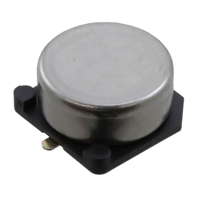
Supercapacitors
FC Series
Overview
Applications
FC Series Supercapacitors, also known as Electric
Double-Layer Capacitors (EDLCs), are surface mount type
components intended for high energy storage applications.
The FC Series is designed specifically for reflow soldering,
allowing them to be attached to a printed circuit board
(PCB) directly.
Supercapacitors have characteristics ranging from
traditional capacitors and batteries. As a result,
supercapacitors can be used like a secondary battery
when applied in a DC circuit. These devices are best suited
for use in low voltage DC hold-up applications such as
embedded microprocessor systems with flash memory.
Benefits
• Surface mount without holder
• Wide range of temperature from −25°C to +70°C
• Maintenance free
• Maximum operating voltages of 3.5 and 5.5 VDC
• Highly reliable against liquid leakage
• Lead-free and RoHS Compliant
Part Number System
FC
0H
Series
Maximum
Surface Mount Operating Voltage
FCS
FC
0V = 3.5 VDC
0H = 5.5 VDC
104
Capacitance Code
First two digits
represent significant
figures. Third digit
specifies number of
zeros to follow µF
code.
Z
F
TB
R
24
Capacitance
Environmental Tape Type Orientation Tape Width
Tolerance
Z=
−20/+80%
F=
Lead-free
TB =
Embossed
R=
Positive
electrode
forward
–SS
C-Spec
24 = 24 mm –SS = 3 digit
32 = 32 mm serial number
44 = 44 mm marked on top
Blank = No serial
number marking
One world. One KEMET
© KEMET Electronics Corporation • KEMET Tower • One East Broward Boulevard�
Fort Lauderdale, FL 33301 USA • 954-766-2800 • www.kemet.com
S6011_FC • 7/17/2020
1
�Supercapacitors – FC Series
Dimensions – Millimeters
B ±0.2
D ±0.5
A ±0.2
H
Maximum
Negative
Terminal
L
W ±0.1
Positive
Terminal
K
I
P
I
Part Number
D
H
A
B
I
W
P
K
L
Reflow Peak
Temperature
FC0H473ZFTBR24
FC0H104ZFTBR24
FC0H224ZFTBR24
FC0H474ZFTBR32–SS
FC0H105ZFTBR44–SS
FC0V104ZFTBR24
FC0V224ZFTBR24
FC0V474ZFTBR24
10.5
10.5
10.5
16.0
21.0
10.5
10.5
10.5
5.5
5.5
8.5
9.5
10.5
5.5
5.5
8.5
10.8
10.8
10.8
16.3
21.6
10.8
10.8
10.8
10.8
10.8
10.8
16.3
21.6
10.8
10.8
10.8
3.6±0.5
3.6±0.5
3.6±0.5
6.8±1.0
7.0±1.0
3.6±0.5
3.6±0.5
3.6±0.5
1.2
1.2
1.2
1.2
1.4
1.2
1.2
1.2
5.0
5.0
5.0
5.0
10.0
5.0
5.0
5.0
0.7±0.3
0.7±0.3
0.7±0.3
1.2±0.5
1.2±0.5
0.7±0.3
0.7±0.3
0.7±0.3
0 (+0.3/−0.1)
0 (+0.3/−0.1)
0 (+0.3/−0.1)
0 (+0.5/−0.1)
0 (+0.5/−0.1)
0 (+0.3/−0.1)
0 (+0.3/−0.1)
0 (+0.3/−0.1)
235°C
235°C
235°C
235°C
235°C
235°C
235°C
235°C
FCS0H473ZFTBR24
FCS0H104ZFTBR24
FCS0H224ZFTBR24
FCS0V104ZFTBR24
FCS0V224ZFTBR24
FCS0V474ZFTBR24
10.7
10.7
10.7
10.7
10.7
10.7
5.5
5.5
8.5
5.5
5.5
8.5
10.8
10.8
10.8
10.8
10.8
10.8
10.8
10.8
10.8
10.8
10.8
10.8
3.9±0.5
3.9±0.5
3.9±0.5
3.9±0.5
3.9±0.5
3.9±0.5
1.2
1.2
1.2
1.2
1.2
1.2
5.0
5.0
5.0
5.0
5.0
5.0
0.9±0.3
0.9±0.3
0.9±0.3
0.9±0.3
0.9±0.3
0.9±0.3
0 (+0.3/−0.1)
0 (+0.3/−0.1)
0 (+0.3/−0.1)
0 (+0.3/−0.1)
0 (+0.3/−0.1)
0 (+0.3/−0.1)
260°C
260°C
260°C
260°C
260°C
260°C
© KEMET Electronics Corporation • KEMET Tower • One East Broward Boulevard�
Fort Lauderdale, FL 33301 USA • 954-766-2800 • www.kemet.com
S6011_FC • 7/17/2020
2
�Supercapacitors – FC Series
Performance Characteristics
Supercapacitors should not be used for applications such as ripple absorption because of their high internal resistance
(several hundred mΩ to a hundred Ω) compared to aluminum electrolytic capacitors. Thus, its main use would be
similar to that of secondary battery such as power back-up in DC circuit. The following list shows the characteristics of
supercapacitors as compared to aluminum electrolytic capacitors for power back-up and secondary batteries.
Secondary Battery
Capacitor
NiCd
Lithium Ion
Aluminum Electrolytic
Supercapacitor
Back-up ability
–
–
–
–
Eco-hazard
Cd
–
–
–
−20 to +60°C
−20 to +50°C
−55 to +105°C
−40 to +85°C
(FR, FT, FMR type)
Few hours
Few hours
Few seconds
Few seconds
Approximately
500 times
Approximately
500 to 1,000 times
Limitless (*1)
Limitless (*1)
Yes
Yes
None
None
Flow Soldering
Not applicable
Not applicable
Applicable
Applicable
Automatic Mounting
Not applicable
Not applicable
Applicable
Leakage, explosion
Leakage, combustion,
explosion, ignition
Applicable
(FM and FC series)
Heat-up, explosion
Gas emission (*2)
Operating Temperature Range
Charge Time
Charge/Discharge Life Time
Restrictions on
Charge/Discharge
Safety Risks
(*1) Aluminum electrolytic capacitors and supercapacitors have limited lifetime. However, when used under proper conditions, both can operate within a
predetermined lifetime.
(*2) There is no harm as it is a mere leak of water vapor which transitioned from water contained in the electrolyte (diluted sulfuric acid). However,
application of abnormal voltage surge exceeding maximum operating voltage may result in leakage and explosion.
Typical Applications
Intended Use (Guideline)
Power Supply (Guideline)
Long time back-up
500 μA and below
Application
Examples of Equipment
Series
CMOS microcomputer,
IC for clocks
CMOS microcomputer,
static RAM/DTS
(digital tuning system)
FC series
Environmental Compliance
All KEMET supercapacitors are RoHS Compliant.
© KEMET Electronics Corporation • KEMET Tower • One East Broward Boulevard�
Fort Lauderdale, FL 33301 USA • 954-766-2800 • www.kemet.com
S6011_FC • 7/17/2020
3
�Supercapacitors – FC Series
Table 1 – Ratings & Part Number Reference
Nominal
Capacitance
Discharge
System (F)
Maximum
Operating
Voltage (VDC)
Part Number
Maximum ESR
at 1 kHz (Ω)
Maximum
Voltage Holding
Current at 30 Characteristic Weight (g)
Minutes (mA)
Minimum (V)
FC0V104ZFTBR24
3.5
0.10
50
0.09
—
1.0
FCS0V104ZFTBR24
3.5
0.10
100
0.09
—
1.0
FC0V224ZFTBR24
3.5
0.22
25
0.20
—
1.0
FCS0V224ZFTBR24
3.5
0.22
50
0.20
—
1.0
FC0V474ZFTBR24
3.5
0.47
25
0.42
—
1.4
FCS0V474ZFTBR24
3.5
0.47
50
0.42
—
1.4
FC0H473ZFTBR24
5.5
0.047
50
0.071
4.2
1.0
FCS0H473ZFTBR24
5.5
0.047
100
0.071
4.2
1.0
FC0H104ZFTBR24
5.5
0.10
25
0.15
4.2
1.0
FCS0H104ZFTBR24
5.5
0.10
50
0.15
4.2
1.0
FC0H224ZFTBR24
5.5
0.22
25
0.33
4.2
1.4
FCS0H224ZFTBR24
5.5
0.22
50
0.33
4.2
1.4
FC0H474ZFTBR32–SS
5.5
0.47
13
0.71
4.2
4.0
FC0H105ZFTBR44–SS
5.5
1.0
7
1.50
4.2
6.7
Part numbers in bold type represent popularly purchased components.
C
Land Pattern
B
A
B
Land Pattern
Lead Terminal
Diameter (mm)
A
B
C
A
B
C
10.5
5.0
4.9
2.5
5.0
3.6
1.2
10.7
5.0
4.9
2.5
5.0
3.9
1.2
16
5.0
10.0
2.5
5.0
6.8
1.2
21
10.0
10.5
3.5
10.0
7.0
1.4
© KEMET Electronics Corporation • KEMET Tower • One East Broward Boulevard�
Fort Lauderdale, FL 33301 USA • 954-766-2800 • www.kemet.com
S6011_FC • 7/17/2020
4
�Supercapacitors – FC Series
Precautions for Use
• This series is exclusively for reflow soldering. It is designed for thermal conduction system such as combination use of
infrared ray and heat blow. Consult with KEMET before applying other methods.
• The reflow condition must be kept within reflow profile graphs shown below.
• Applying reflow soldering is limited to 2 times. After the first reflow, cool down the capacitor thoroughly to 5 – 35°C
before the second reflow.
Always consult with KEMET when applying reflow soldering in a more severe condition than the condition described here.
FCS Type
FC Type
Reflow Profile
Reflow Profile
300
260°C
250
200
200°C
150
150°C
250
217°C
70
seconds
150
seconds
100
Temperature on the
Capacitor Top (°C)
Temperature on the
Capacitor Top and
Terminals (°C)
300
50
0
0
50
100
150
200
250
300
350
200
235°C
200°C
160°C
150
120 seconds
100
50
30 seconds
0
400
Time (seconds)
Above "Reflow Profile" graph indicates temperature at the terminals and
capacitor top.
Above "Reflow Profile" graph indicates temperature at capacitor top.
Below +260°C
Over +255°C
Within 10 seconds
Over +230°C
Within 45 seconds
Over +220°C
Within 60 seconds
Over +217°C
Within 70 seconds
Time between +150°C to
+200°C (temperature zone
over +170°C within 50
seconds)
150 seconds
© KEMET Electronics Corporation • KEMET Tower • One East Broward Boulevard�
Fort Lauderdale, FL 33301 USA • 954-766-2800 • www.kemet.com
Allowable Time for Exceeding 200°C with Peak Temperature
Peak Temperature (°C)
Peak Temperature
Time (seconds)
250
240
230
220
Recommended Condition Range
210
200
0
10
20
30
Time (seconds)
40
50
S6011_FC • 7/17/2020
60
5
�Supercapacitors – FC Series
Specifications
Item
FC 5.5 V Type, 3.5 V Type
Test Conditions
(conforming to JIS C 5160-1)
Category Temperature Range
−25°C to +70°C
Maximum Operating Voltage
5.5 VDC, 3.5 VDC
Capacitance
Refer to Table 1
Refer to “Measurement Conditions”
Capacitance Allowance
+80%, −20%
Refer to “Measurement Conditions”
ESR
Refer to Table 1
Measured at 1 kHz, 10 mA; See also
“Measurement Conditions”
Current (30 minutes value)
Refer to Table 1
Refer to “Measurement Conditions”
Surge voltage:
Capacitance
> 90% of initial ratings
ESR
≤ 120% of initial ratings
Current (30 minutes value)
≤ 120% of initial ratings
Appearance
No obvious abnormality
Charge:
Discharge:
Number of cycles:
Series resistance:
* Surge
Capacitance
ESR
Capacitance
ESR
* Characteristics in
Different Temperature
Phase 2
≤ 200% of initial value
Phase 5
Current (30 minutes value)
* Solder Heat Resistance
Satisfy initial ratings
No obvious abnormality
Satisfy initial ratings
Current (30 minutes value)
Appearance
No obvious abnormality
Capacitance
* Temperature Cycle
ESR
10 to 55 Hz
6 hours
Satisfy initial ratings
Capacitance
ESR
Conforms to 4.13
Frequency:
Testing Time:
Satisfy initial ratings
Current (30 minutes value)
Appearance
+25 ±2°C
−25 ±2°C
+25 ±2°C
+70 ±2°C
+25 ±2°C
Satisfy initial ratings
Capacitance
* Vibration Resistance
Conforms to 4.17
Phase 1:
Phase 2:
Phase 4:
Phase 5:
Phase 6:
Within ±20% of initial value
Phase 6
Current (30 minutes value)
ESR
Satisfy initial ratings
Cooled down to ambient temperature after
reflow soldering, then the product must
fulfill the condition stated left.
(See Precautions for Use)
Conforms to 4.12
Temperature
Condition:
Current (30 minutes value)
Appearance
0Ω
70 ±2°C
1.5 CV (mA) or below
Capacitance
ESR
≤ 400% of initial value
Phase 3
Capacitance
ESR
≥ 50% of initial value
Discharge
Resistance:
Temperature:
4.0 V (3.5 V type,3.6
V type)
6.3 V (5.5 V type)
30 seconds
9 minutes 30 seconds
1,000
0.043 F, 0.047 F 300 Ω
0.068 F
240 Ω
0.10 F
150 Ω
0.22 F
56 Ω
0.47 F
30 Ω
1.0 F
15 Ω
No obvious abnormality
Number of cycles:
−25°C » Room
temperature »
+70°C » Room
temperature
5 cycles
* Must fulfill the above condition after reflow soldering.
© KEMET Electronics Corporation • KEMET Tower • One East Broward Boulevard�
Fort Lauderdale, FL 33301 USA • 954-766-2800 • www.kemet.com
S6011_FC • 7/17/2020
6
�Supercapacitors – FC Series
Specifications cont.
Item
* High Temperature and
High Humidity Resistance
* High Temperature Load
FC 5.5 V Type, 3.5 V Type
Capacitance
Within ±20% of initial value
ESR
≤ 120% of initial ratings
Current (30 minutes value)
≤ 120% of initial ratings
Appearance
No obvious abnormality
Capacitance
Within ±30% of initial value
ESR
< 200% of initial ratings
Current (30 minutes value)
< 200% of initial ratings
Appearance
No obvious abnormality
5.5 V type:
Voltage between terminal leads
> 4.2 V
* Self Discharge Characteristics
(Voltage Holding Characteristics)
3.5 V type:
Not specified
Test Conditions
(conforming to JIS C 5160-1)
Conforms to 4.14
Temperature:
Relative humidity:
Testing time:
Conforms to 4.15
Voltage applied:
Series protection
resistance:
Testing time:
Charging condition
Voltage applied:
Series resistance:
Charging time:
+40 ±2°C
90 to 95% RH
240 ±8 hours
Maximum operating
voltage
0Ω
1,000 +48 (+48/−0)
hours
5.0 VDC (Terminal at
the case side must be
negative)
0Ω
24 hours
Storage
Let stand for 24 hours in condition
described below with terminals opened.
Ambient
< 25°C
temperature:
< 70% RH
Relative humidity:
* Must fulfill the above condition after reflow soldering.
Construction
Outer Case
Element
Terminals with
Insulator
Base Plate
© KEMET Electronics Corporation • KEMET Tower • One East Broward Boulevard�
Fort Lauderdale, FL 33301 USA • 954-766-2800 • www.kemet.com
S6011_FC • 7/17/2020
7
�Supercapacitors – FC Series
Marking
D = 10.5 mm
D = 16 & 21 mm
Nominal
Capacitance
Series
Name
Polarity
(Negative)
Maximum
Operating
Voltage
Polarity
(Negative)
Date
Code
Date
Code
Trademark
Maximum
Operating
Voltage
Nominal
Capacitance
Serial
Number
D = 10.7 mm
Nominal
Capacitance
Polarity
(Negative)
Maximum
Operating
Voltage
Date
Code
FCS Type
Displays nominal capacitance, maximum operating voltage serial number, polarity, etc.
© KEMET Electronics Corporation • KEMET Tower • One East Broward Boulevard�
Fort Lauderdale, FL 33301 USA • 954-766-2800 • www.kemet.com
S6011_FC • 7/17/2020
8
�Supercapacitors – FC Series
Tape & Reel Packaging Information – Millimeters
E
B
C
D
R:1
A
t
W
Mark
TBR24
TBR32
TBR44
A
380±2
330±2
380±2
100±1
100±1
B
Product height 5.5 mm
80±1
Product height 8.5 mm
100±1
C
13±0.5
13±0.5
13±0.5
D
21±0.8
21±0.8
21±0.8
E
2±0.5
2±0.5
2±0.5
33.5±1.0
45.5±1.0
2.0
2.0
W
t
Product height 5.5 mm
25.5±0.5
Product height 8.5 mm
25.5±1.0
2.0
© KEMET Electronics Corporation • KEMET Tower • One East Broward Boulevard�
Fort Lauderdale, FL 33301 USA • 954-766-2800 • www.kemet.com
S6011_FC • 7/17/2020
9
�Supercapacitors – FC Series
Tape & Reel Packaging Information – Millimeters cont.
ø D0
A
W
B
B
G
W
F
A
P0
E
P0
E
P2
P2
t1
ø D0
F
Sprocket hole
t1
t2
Indented square-hole
for fitting super capacitors
P1
Forward direction
Super capacitors fitting
on square-hole
Mark
W
A
B
P0
P1
P2
F
ø D0
t1
E
t2
G
t2
Super capacitors fitting
on square-hole
TBR24
24.0
11.4
13.0
4.0
16.0
2.0
11.5
1.55
0.4
1.75
Product height 5.5 mm
Product height 8.5 mm
–
6.0
8.4
P1
R0.75
TBR32
TBR44
32.0
18.0
20.0
4.0
24.0
2.0
14.2
1.55
0.5
1.75
44.0
23.0
25.0
4.0
32.0
2.0
20.2
1.55
0.5
1.75
10.0
12.0
28.4
40.4
0.2
Ammo Pack Packaging Information
Part Number
Quantity per Reel
FC0H473ZFTBR24
FC0H104ZFTBR24
FC0H224ZFTBR24
FC0H474ZFTBR32–SS
FC0H105ZFTBR44–SS
FC0V104ZFTBR24
FC0V224ZFTBR24
FC0V474ZFTBR24
FCS0H473ZFTBR24
FCS0H104ZFTBR24
FCS0H224ZFTBR24
FCS0V104ZFTBR24
FCS0V224ZFTBR24
FCS0V474ZFTBR24
1,000 pieces/reel
1,000 pieces/reel
500 pieces/reel
200 pieces/reel
150 pieces/reel
1,000 pieces/reel
1,000 pieces/reel
500 pieces/reel
1,000 pieces/reel
1,000 pieces/reel
500 pieces/reel
1,000 pieces/reel
1,000 pieces/reel
500 pieces/reel
© KEMET Electronics Corporation • KEMET Tower • One East Broward Boulevard�
Fort Lauderdale, FL 33301 USA • 954-766-2800 • www.kemet.com
S6011_FC • 7/17/2020
10
�Supercapacitors – FC Series
Measurement Conditions
Capacitance (Charge System)
Capacitance is calculated from expression (9) by measuring the charge time constant (τ) of the capacitor (C). Prior to
measurement, the capacitor is discharged by shorting both pins of the device for at least 30 minutes. In addition, use the polarity
indicator on the device to determine correct orientation of capacitor for charging.
τ
Rc
Capacitance:
C=
Eo:
3.0 (V) Product with maximum operating voltage of 3.5 V
5.0 (V) Product with maximum operating voltage of 5.5 V
6.0 (V) Product with maximum operating voltage of 6.5 V
10.0 (V) Product with maximum operating voltage of 11 V
12.0 (V) Product with maximum operating voltage of 12 V
τ:
Time from start of charging until Vc becomes 0.632 Eo (V)
(seconds)
Rc:
See table below (Ω).
(F) (9)
Switch
Eo
Rc
C
+
Vc
–
Charge Resistor Selection Guide
Cap
0.010 F
0.022 F
0.033 F
0.047 F
0.10 F
FA
FE
FS
FYD
FY
FYH
FR
FM, FME
FMR
–
–
–
–
–
–
1,000 Ω
–
1,000 Ω 2,000 Ω 2,000 Ω 2,000 Ω
–
–
–
–
–
–
1,000 Ω 1,000 Ω 1,000 Ω 2,000 Ω 1,000 Ω 1,000 Ω
510 Ω 510 Ω 510 Ω 1,000 Ω 510 Ω 1,000 Ω
0.22 F
200 Ω
200 Ω
200 Ω
510 Ω
510 Ω
0.33 F
0.47 F
1.0 F
1.4 F
1.5 F
2.2 F
2.7 F
3.3 F
4.7 F
5.0 F
5.6 F
10.0 F
22.0 F
50.0 F
100.0 F
200.0 F
–
100 Ω
51 Ω
–
–
–
–
–
–
–
–
–
–
–
–
–
–
100 Ω
51 Ω
–
51 Ω
–
–
–
–
–
–
–
–
–
–
–
–
100 Ω
100 Ω
–
–
–
–
–
–
100 Ω
–
–
–
–
–
–
–
200 Ω
100 Ω
200 Ω
–
100 Ω
–
–
–
–
–
–
–
–
–
–
–
200 Ω
100 Ω
–
–
–
–
–
–
–
–
–
–
–
–
–
FMC
FG,
FGR
FGH
FT
5,000 Ω
–
5,000 Ω
–
–
2,000 Ω
–
2,000 Ω
–
–
Discharge
–
–
–
–
2000 Ω
1,000 Ω 2,000 Ω
–
–
1000 Ω
1,000 Ω 1,000 Ω Discharge 510 Ω
0H: Discharge
510 Ω
–
1,000 Ω Discharge 200 Ω
0V: 1000 Ω
–
–
Discharge
–
–
–
200 Ω
–
–
1,000 Ω Discharge 100 Ω
100 Ω
–
–
510 Ω Discharge 100 Ω
–
–
–
–
–
–
–
–
–
510 Ω
–
–
–
–
–
200 Ω
–
51 Ω
–
–
–
–
–
–
–
–
–
–
–
51 Ω
–
–
–
100 Ω
–
–
–
–
–
–
–
–
–
–
–
–
–
20 Ω
–
–
–
–
–
–
–
–
–
–
–
–
–
–
–
–
–
–
–
–
–
–
–
–
–
–
–
–
–
–
FC, FCS
HV
–
Discharge
–
–
Discharge
–
–
–
–
–
Discharge
–
–
Discharge
Discharge
–
–
–
–
–
–
–
–
–
–
–
–
–
–
–
Discharge
–
–
–
Discharge
–
Discharge
–
–
Discharge
Discharge
Discharge
Discharge
Discharge
*Capacitance values according to the constant current discharge method.
*HV Series capacitance is measured by discharge system.
© KEMET Electronics Corporation • KEMET Tower • One East Broward Boulevard�
Fort Lauderdale, FL 33301 USA • 954-766-2800 • www.kemet.com
S6011_FC • 7/17/2020
11
�Supercapacitors – FC Series
Measurement Conditions cont.
Capacitance (Discharge System)
As shown in the diagram below, charging is performed for a duration of 30 minutes once the voltage of the capacitor
terminal reaches 5.5 V. Then, use a constant current load device and measure the time for the terminal voltage to drop
from 3.0 to 2.5 V upon discharge at 0.22 mA per 0.22 F, for example, and calculate the static capacitance according to the
equation shown below.
Note: The current value is 1 mA discharged per 1 F.
C=
I × (T 2 -T 1 )
V 1 -V 2
(F)
5.5 V
A
C
V
(V)
0.22 mA (I)
SW
R
5.5 V
V 1 : 3.0 V
V1
V 2 : 2.5 V
V2
T1
T2
Time (seconds)
30 minutes
Capacitance (Discharge System – 3.5 V, 3.6 V)
As shown in the diagram below, charging is performed for a duration of 30 minutes once the voltage of the capacitor
terminal reaches 3.5 V (3.6 V). Then, use a constant current load device and measure the time for the terminal voltage to
drop from 1.8 to 1.5 V upon discharge at 1.0 mA per 1.0 F, for example, and calculate the static capacitance according to the
equation shown below.
(V)
SW
C=
I × (T 2 -T 1 )
V 1 -V 2
(F)
3.5 V
(3.6 V)
A
C
V
R
3.5 V
(3.6 V)
V 1 : 1.8 V
V1
V 2 : 1.5 V
V2
T1
T2
Time (seconds)
30 minutes
Capacitance (Discharge System – HV Series)
As shown in the diagram below, charging is performed for a duration of 30 minutes once the voltage of the capacitor
terminal reaches maximum operating voltage. Then, use a constant current load device and measure the time for the
terminal voltage to drop from 2.0 to 1.5 V upon discharge at 1.0 mA per 1.0 F, and calculate the static capacitance according
to the equation shown below.
(V)
SW
C=
I × (T 2 -T 1 )
V 1 -V 2
(F)
2.7 V
(2.5 V)
V
A
C
R
2.7 V
(2.5 V)
V 1 : 2.0 V
V1
V 2 : 1.5 V
V2
T1
T2
Time (seconds)
30 minutes
© KEMET Electronics Corporation • KEMET Tower • One East Broward Boulevard�
Fort Lauderdale, FL 33301 USA • 954-766-2800 • www.kemet.com
S6011_FC • 7/17/2020
12
�Supercapacitors – FC Series
Measurement Conditions cont.
Equivalent Series Resistance (ESR)
ESR shall be calculated from the equation below.
ESR =
VC
0.01
10mA
(Ω)
f:1kHz
C
VC
Current (at 30 minutes after charging)
Current shall be calculated from the equation below. Prior to measurement, both lead terminals must be short-circuited for
a minimum of 30 minutes. The lead terminal connected to the metal can case is connected to the negative side of the power
supply.
Eo: 2.5 VDC (HV Series 50 F)
2.7 VDC (HV Series except 50 F)
3.0 VDC (3.5 V type)
3.6 VDC (3.6 V type)
5.0 VDC (5.5 V type)
6.0 VDC (6.5 V type)
10.0 VDC (11 V type)
12.0 VDC (12 V type)
VR
Current =
VR
RC
(A)
EO
RC
SW
+
C
-
Rc: 1,000 Ω (0.01 F, 0.022 F, 0.047 F)
100 Ω (0.10 F, 0.22 F, 0.33 F, 0.47 F)
10 Ω (1.0 F, 1.4 F, 1.5 F, 2.2 F, 3.3 F, 4.7 F, 5.6 F)
2.2 Ω (HV Series)
However, FS Seres 11 V type and 12 V type
100 Ω 0.47 F, 1.0 F
10 Ω 5.0 F
Self-Discharge Characteristic (0H – 5.5 V Products)
The self-discharge characteristic is measured by charging a voltage of 5.0 VDC (charge protection resistance: 0 Ω)
according to the capacitor polarity for 24 hours, then releasing between the pins for 24 hours and measuring the pin-topin voltage. The test should be carried out in an environment with an ambient temperature of 25° C or below and relative
humidity of 70% RH or below. The soldering is checked.
4. Dismantling
There is a small amount of electrolyte stored within the capacitor. Do not attempt to dismantle as direct skin contact with
the electrolyte will cause burning. This product should be treated as industrial waste and not is not to be disposed of by fi re.
© KEMET Electronics Corporation • KEMET Tower • One East Broward Boulevard�
Fort Lauderdale, FL 33301 USA • 954-766-2800 • www.kemet.com
S6011_FC • 7/17/2020
13
�Supercapacitors – FC Series
Notes on Using Supercapacitors or Electric Double-Layer Capacitors (EDLCs)
1. Circuitry Design
1.1 Useful life
The FC Series Supercapacitor (EDLC) uses an electrolyte in a sealed container. Water in the electrolyte can evaporate
while in use over long periods of time at high temperatures, thus reducing electrostatic capacity which in turn will create
greater internal resistance. The characteristics of the supercapacitor can vary greatly depending on the environment in
which it is used. Basic breakdown mode is an open mode due to increased internal resistance.
1.2 Fail rate in the field
Based on field data, the fail rate is calculated at approximately 0.006 Fit. We estimate that unreported failures are ten
times this amount. Therefore, we assume that the fail rate is below 0.06 Fit.
1.3 Exceeding maximum usable voltage
Performance may be compromised and in some cases leakage or damage may occur if applied voltage exceeds
maximum working voltage.
1.4 Use of capacitor as a smoothing capacitor (ripple absorption)
As supercapacitors contain a high level of internal resistance, they are not recommended for use as smoothing
capacitors in electrical circuits. Performance may be compromised and, in some cases, leakage or damage may occur if
a supercapacitor is used in ripple absorption.
1.5 Series connections
As applied voltage balance to each supercapacitor is lost when used in series connection, excess voltage may be
applied to some supercapacitors, which will not only negatively affect its performance but may also cause leakage
and/or damage. Allow ample margin for maximum voltage or attach a circuit for applying equal voltage to each
supercapacitor (partial pressure resistor/voltage divider) when using supercapacitors in series connection. Also,
arrange supercapacitors so that the temperature between each capacitor will not vary.
1.6 Case Polarity
The supercapacitor is manufactured so that the terminal on the outer case is negative (-). Align the (-) symbol during
use. Even though discharging has been carried out prior to shipping, any residual electrical charge may negatively affect
other parts.
1.7 Use next to heat emitters
Useful life of the supercapacitor will be significantly affected if used near heat emitting items (coils, power transistors
and posistors, etc.) where the supercapacitor itself may become heated.
1.8 Usage environment
This device cannot be used in any acidic, alkaline or similar type of environment.
© KEMET Electronics Corporation • KEMET Tower • One East Broward Boulevard�
Fort Lauderdale, FL 33301 USA • 954-766-2800 • www.kemet.com
S6011_FC • 7/17/2020
14
�Supercapacitors – FC Series
Notes on Using Supercapacitors or Electric Double-Layer Capacitors (EDLCs) cont.
2. Mounting
2.1 Mounting onto a reflow furnace
Except for the FC series, it is not possible to mount this capacitor onto an IR / VPS reflow furnace. Do not immerse the
capacitor into a soldering dip tank.
2.2 Flow soldering conditions
Keep solder under 260°C and soldering time to within 10 seconds when using the flow automatic soldering method.
(Except for the FC and HV series)
2.3 Installation using a soldering iron
Care must be taken to prevent the soldering iron from touching other parts when soldering. Keep the tip of the soldering
iron under 400°C and soldering time to within 3 seconds. Always make sure that the temperature of the tip is controlled.
Internal capacitor resistance is likely to increase if the terminals are overheated.
2.4 Lead terminal processing
Do not attempt to bend or polish the capacitor terminals with sand paper, etc. Soldering may not be possible if the
metallic plating is removed from the top of the terminals.
2.5 Cleaning, Coating, and Potting
Except for the FM series, cleaning, coating and potting must not be carried out. Consult KEMET if this type of procedure
is necessary. Terminals should be dried at less than the maximum operating temperature after cleaning.
3. Storage
3.1 Temperature and humidity
Make sure that the supercapacitor is stored according to the following conditions: Temperature: 5 – 35°C (Standard
25°C), Humidity: 20 – 70% (Standard: 50%). Do not allow the build up of condensation through sudden temperature
change.
3.2 Environment conditions
Make sure there are no corrosive gasses such as sulfur dioxide, as penetration of the lead terminals is possible. Always
store this item in an area with low dust and dirt levels. Make sure that the packaging will not be deformed through heavy
loading, movement and/or knocks. Keep out of direct sunlight and away from radiation, static electricity and magnetic
fields.
3.3 Maximum storage period
This item may be stored up to one year from the date of delivery if stored at the conditions stated above.
© KEMET Electronics Corporation • KEMET Tower • One East Broward Boulevard�
Fort Lauderdale, FL 33301 USA • 954-766-2800 • www.kemet.com
S6011_FC • 7/17/2020
15
�Supercapacitors – FC Series
KEMET Electronics Corporation Sales Offices
For a complete list of our global sales offi ces, please visit www.kemet.com/sales.
Disclaimer
All product specifi cations, statements, information and data (collectively, the “Information”) in this datasheet are subject to change. The customer is responsible for
checking and verifying the extent to which the Information contained in this publication is applicable to an order at the time the order is placed. All Information given
herein is believed to be accurate and reliable, but it is presented without guarantee, warranty, or responsibility of any kind, expressed or implied.
Statements of suitability for certain applications are based on KEMET Electronics Corporation’s (“KEMET”) knowledge of typical operating conditions for such
applications, but are not intended to constitute – and KEMET specifi cally disclaims – any warranty concerning suitability for a specifi c customer application or use.
The Information is intended for use only by customers who have the requisite experience and capability to determine the correct products for their application. Any
technical advice inferred from this Information or otherwise provided by KEMET with reference to the use of KEMET’s products is given gratis, and KEMET assumes no
obligation or liability for the advice given or results obtained.
Although KEMET designs and manufactures its products to the most stringent quality and safety standards, given the current state of the art, isolated component
failures may still occur. Accordingly, customer applications which require a high degree of reliability or safety should employ suitable designs or other safeguards
(such as installation of protective circuitry or redundancies) in order to ensure that the failure of an electrical component does not result in a risk of personal injury or
property damage.
Although all product–related warnings, cautions and notes must be observed, the customer should not assume that all safety measures are indicted or that other
measures may not be required.
When providing KEMET products and technologies contained herein to other countries, the customer must abide by the procedures and provisions stipulated in all
applicable export laws and regulations, including without limitation the International Traffi c in Arms Regulations (ITAR), the US Export Administration Regulations
(EAR) and the Japan Foreign Exchange and Foreign Trade Act.
KEMET is a registered trademark of KEMET Electronics Corporation.
© KEMET Electronics Corporation • KEMET Tower • One East Broward Boulevard�
Fort Lauderdale, FL 33301 USA • 954-766-2800 • www.kemet.com
S6011_FC • 7/17/2020
16
�