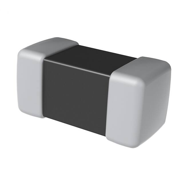
Chip Inductors
High Current Multilayer Chip Power Inductor L-DMI
Overview
Applications
KEMET L-DMI ferrite-based Multilayer Chip Power
Inductors are ideal for use in DC to DC switching power
supplies. The small size of this chip inductor makes it
suitable for mobile equipement that requires tight space
both in dimension and in height. The internal printed coil
structure creates a closed magnetic circuit, which acts as
a magnetic shield eliminating crosstalk, thus permitting
higher mounting densities. The multilayer block structure
yields higher reliability. In addition, the inductor shows
excellent low DC power dissipation, due to low Rdc with
a high aspect ratio internal conductor that stands on
unique green sheet and printing technologies.
• Switching DC-DC power supplies
• Wearables
• Smartphone
• Tablet device
• Digital still camera
• HDD
Benefits
• Unique green sheet and printing technologies
• High reliability
• High current
• Low DCR
• Inductance value from 0.47 – 4.7 µH
• Rated current range from 0.65 – 1.8 A
• Operating temperature range from –40°C to +85°C
• Low profile 1.2 mm maximum
Part Number System
L
0603
C
1R0
M
DMI
T
Inductor
EIA Case Size
(L" x W")
Specification
Inductance
Value (µH)
Inductance
Tolerance
Series
Packaging
0603 (1608 in mm)
0805 (2012 in mm)
0806 (2016 in mm)
1008 (2520 in mm)
C = Commercial
L = 0.8 mm maximum height
S = High saturation type
Q = 1.2 mm maximum height
DMI = High current
multilayer chip type
T = Tape & Reel
R = decimal point
Examples:
R47 = 0.47 µH
1R0 = 1.0 µH
M = ±20%
One world. One KEMET
© KEMET Electronics Corporation • KEMET Tower • One East Broward Boulevard�
Fort Lauderdale, FL 33301 USA • 954-766-2800 • www.kemet.com
L9014_L-DMI • 7/7/2020
1
�Chip Inductors
High Current Multilayer Chip Power Inductor L-DMI
Dimensions – Millimeters (Inches)
Dimensions - Millimeters (Inches)
W
Land Pattern - Millimeters
Land Pattern
L
Chip Inductor
B
T
Solder−resist
C
B
A
B
EIA
Size
Code
Metric
Size
Code
L
Length
W
Width
T
Thickness
B
Bandwidth
A
B
C
0603
1608
1.60 (0.063)
±0.15 (0.006)
0.80 (0.031)
±0.15 (0.006)
0.95 (0.037)
Maximum
0.30 (0.012)
±0.20 (0.008)
0.8 ~ 1.0
0.6 ~ 0.8
0.6 ~ 0.8
0805
2012
0.50 (0.020)
±0.30 (0.012)
0.50 (0.020)
±0.30 (0.012)
0.9 ~ 1.6
0.8 ~ 1.2
0.8 ~ 1.2
1.2 ~ 2.0
1008
2520
2.50 (0.098)
±0.20 (0.008)
2.00 (0.079)
±0.20 (0.008)
1.00 (0.039)
Maximum
1.00 (0.039)
Maximum
0.80 (0.031)
Maximum
1.00 (0.039)
Maximum
1.20 (0.047)
Maximum
0.8 ~ 1.2
2016
1.25 (0.049)
±0.20 (0.008)
1.60 (0.063)
±0.20 (0.008)
0.8 ~ 1.2
0806
2.00 (0.079)
±0.20 (0.008)
2.00 (0.079)
±0.20 (0.008)
1.0 ~ 1.4
0.6 ~ 1.0
1.8 ~ 2.2
0.50 (0.020)
±0.30 (0.012)
Performance Characteristics
Item
Operating Temperature Range
Rated Inductance Range
Inductance Tolerance
Inductance Measurement Condition
Rated Current Range
Rated DC Resistance Range Typical
Rated DC Resistance Range Maximum
Performance Characteristics
–40°C to +85°C
0.47 – 4.7 µH
±20%
1 MHz
0.65 – 1.8 A
0.04 – 0.27 Ω
0.05 – 0.3 Ω
© KEMET Electronics Corporation • KEMET Tower • One East Broward Boulevard�
Fort Lauderdale, FL 33301 USA • 954-766-2800 • www.kemet.com
L9014_L-DMI • 7/7/2020
2
�Chip Inductors
High Current Multilayer Chip Power Inductor L-DMI
Environmental Compliance
All KEMET Chip Inductors are RoHS and REACH Compliant.
Table 1 – Ratings & Part Number Reference
1
Part Number
Inductance (µH)
at 1 MHz
Inductance
Tolerance
DC Resistance
(Ω) Typical
DC Resistance
(Ω) Maximum
L0603CR50MDMIT
0.5
L0603C1R0MDMIT
1.0
Rated Current (A)
Maximum1
±20%
0.12
0.15
0.9
±20%
0.17
0.2
0.75
L0603C2R2MDMIT
2.2
±20%
0.27
0.3
0.65
L0805CR47MDMIT
0.47
±20%
0.06
0.08
1.2
L0805C1R0MDMIT
1.0
±20%
0.11
0.14
1
L0805C1R5MDMIT
1.5
±20%
0.15
0.2
0.8
L0805C2R2MDMIT
2.2
±20%
0.15
0.2
0.8
L0805C3R3MDMIT
3.3
±20%
0.2
0.24
0.7
L0805C4R7MDMIT
4.7
±20%
0.23
0.28
0.7
L0806CR47MDMIT
0.47
±20%
0.06
0.075
1.6
L0806C1R0MDMIT
1.0
±20%
0.09
0.12
1.3
L0806C1R5MDMIT
1.5
±20%
0.1
0.13
1.2
L0806C2R2MDMIT
2.2
±20%
0.11
0.14
1.2
L0806C3R3MDMIT
3.3
±20%
0.13
0.16
1.1
L0806C4R7MDMIT
4.7
±20%
0.16
0.2
0.9
L1008CR47MDMIT
0.47
±20%
0.04
0.05
1.8
L1008C1R0MDMIT
1.0
±20%
0.07
0.08
1.4
L1008C1R5MDMIT
1.5
±20%
0.08
0.09
1.3
L1008C2R2MDMIT
2.2
±20%
0.08
0.09
1.3
L1008C3R3MDMIT
3.3
±20%
0.09
0.12
1.2
L1008C4R7MDMIT
4.7
±20%
0.12
0.15
1.1
L1008L1R5MDMIT
1.5
±20%
0.08
0.09
1.3
L1008L2R2MDMIT
2.2
±20%
0.08
0.1
1.2
L1008S1R0MDMIT
1.0
±20%
0.09
0.115
1.2
L1008S2R2MDMIT
2.2
±20%
0.09
0.115
1.2
L1008S4R7MDMIT
4.7
±20%
0.14
0.16
1.1
1.2
L1008Q1R0MDMIT
1.0
±20%
0.09
0.12
L1008Q2R2MDMIT
2.2
±20%
0.12
0.15
1.1
L1008Q3R3MDMIT
3.3
±20%
0.11
0.15
1.1
L1008Q4R7MDMIT
4.7
±20%
0.14
0.16
1.1
Part Number
Inductance (µH)
at 1 MHz
Inductance
Tolerance
DC Resistance
(Ω) Typical
DC Resistance
(Ω) Maximum
Rated Current
(A) Maximum1
T = 40 K rise at rated current at 20°C
© KEMET Electronics Corporation • KEMET Tower • One East Broward Boulevard�
Fort Lauderdale, FL 33301 USA • 954-766-2800 • www.kemet.com
L9014_L-DMI • 7/7/2020
3
�Chip Inductors
High Current Multilayer Chip Power Inductor L-DMI
DC-Superposed Characteristics
L0603CR50MDMIT
Inductance (µH)
Inductance (µH)
L0603C1R0MDMIT
Idc (A)
Idc (A)
Inductance (µH)
L0805CR47MDMIT
Inductance (µH)
L0603C2R2MDMIT
Idc (A)
Inductance (µH)
L0805C1R5MDMIT
Inductance (µH)
L0805C1R0MDMIT
Idc (A)
Idc (A)
© KEMET Electronics Corporation • KEMET Tower • One East Broward Boulevard�
Fort Lauderdale, FL 33301 USA • 954-766-2800 • www.kemet.com
Idc (A)
L9014_L-DMI • 7/7/2020
4
�Chip Inductors
High Current Multilayer Chip Power Inductor L-DMI
DC-Superposed Characteristics cont.
Inductance (µH)
L0805C3R3MDMIT
Inductance (µH)
L0805C2R2MDMIT
Idc (A)
Inductance (µH)
L0806CR47MDMIT
Inductance (µH)
L0805C4R7MDMIT
Idc (A)
Idc (A)
Inductance (µH)
L0806C1R5MDMIT
Inductance (µH)
L0806C1R0MDMIT
Idc (A)
Idc (A)
© KEMET Electronics Corporation • KEMET Tower • One East Broward Boulevard�
Fort Lauderdale, FL 33301 USA • 954-766-2800 • www.kemet.com
Idc (A)
L9014_L-DMI • 7/7/2020
5
�Chip Inductors
High Current Multilayer Chip Power Inductor L-DMI
DC-Superposed Characteristics cont.
L0806C3R3MDMIT
Inductance (µH)
Inductance (µH)
L0806C2R2MDMIT
Idc (A)
Idc (A)
Inductance (µH)
L1008CR47MDMIT
Inductance (µH)
L0806C4R7MDMIT
Idc (A)
Inductance (µH)
L1008C1R5MDMIT
Inductance (µH)
L1008C1R0MDMIT
Idc (A)
Idc (A)
© KEMET Electronics Corporation • KEMET Tower • One East Broward Boulevard�
Fort Lauderdale, FL 33301 USA • 954-766-2800 • www.kemet.com
Idc (A)
L9014_L-DMI • 7/7/2020
6
�Chip Inductors
High Current Multilayer Chip Power Inductor L-DMI
DC-Superposed Characteristics cont.
L1008C3R3MDMIT
Inductance (µH)
Inductance (µH)
L1008C2R2MDMIT
Idc (A)
Idc (A)
Inductance (µH)
L1008L1R5MDMIT
Inductance (µH)
L1008C4R7MDMIT
Idc (A)
Inductance (µH)
L1008S1R0MDMIT
Inductance (µH)
L1008L2R2MDMIT
Idc (A)
Idc (A)
© KEMET Electronics Corporation • KEMET Tower • One East Broward Boulevard�
Fort Lauderdale, FL 33301 USA • 954-766-2800 • www.kemet.com
Idc (A)
L9014_L-DMI • 7/7/2020
7
�Chip Inductors
High Current Multilayer Chip Power Inductor L-DMI
DC-Superposed Characteristics cont.
Inductance (µH)
L1008S4R7MDMIT
Inductance (µH)
L1008S2R2MDMIT
Idc (A)
Inductance (µH)
L1008Q2R2MDMIT
Inductance (µH)
L1008Q1R0MDMIT
Idc (A)
Idc (A)
Inductance (µH)
L1008Q4R7MDMIT
Inductance (µH)
L1008Q3R3MDMIT
Idc (A)
Idc (A)
© KEMET Electronics Corporation • KEMET Tower • One East Broward Boulevard�
Fort Lauderdale, FL 33301 USA • 954-766-2800 • www.kemet.com
Idc (A)
L9014_L-DMI • 7/7/2020
8
�Chip Inductors
High Current Multilayer Chip Power Inductor L-DMI
Taping Specifications - Millimeters (Inches)
0603 Paper Tape 8mm Width
A
B
T
8.0±0.3
(0.315±0.012)
1.75±0.1
(0.069±0.004)
3.5±0.05
(0.138±0.002)
Ø1.5±0.1/−0
(Ø0.059±0.004/−0)
Sprocket
Hole
P
2.0±0.05
(0.079±0.002)
4.0±0.1
(0.157±0.004)
EIA
Case Size
Metric
Case Size
Height
Reel
Quantity
0603
1608
0.8
4,000
Cavity
Pitch
Thickness
A
B
P
T
Nominal
1.0
1.8
4.0
1.1
Tolerance
±0.2
±0.2
±0.1
Maximum
© KEMET Electronics Corporation • KEMET Tower • One East Broward Boulevard�
Fort Lauderdale, FL 33301 USA • 954-766-2800 • www.kemet.com
L9014_L-DMI • 7/7/2020
9
�Chip Inductors
High Current Multilayer Chip Power Inductor L-DMI
Taping Specifications - Millimeters (Inches) cont.
0805, 0806, 1008 Embossed (Plastic) Tape 8mm Width
1.75±0.1
(0.069±0.004)
A
B
T
8.0±0.3
(0.315±0.012)
3.5±0.05
(0.138±0.002)
Ø1.5±0.1/−0
(Ø0.059±0.004/−0)
Sprocket
Hole
K
P
2.0±0.05
(0.079±0.002)
EIA
Metric
Case Size Case Size
4.0±0.1
(0.157±0.004)
Height
Reel
Quantity
Cavity
Pitch
A
B
P
Nominal
1.55
2.30
4.00
Tolerance
±0.2
±0.2
±0.1
Nominal
1.80
2.20
4.00
Tolerance
±0.1
±0.1
±0.1
0805
2012
0.9
3,000
0806
2016
0.9
3,000
0.7
3,000
Nominal
2.3
2.8
4
0.9
3,000
Tolerance
±0.1
±0.1
±0.1
1.1
2,000
Nominal
2.30
2.80
4.00
Tolerance
±0.1
±0.1
±0.1
1008
2520
© KEMET Electronics Corporation • KEMET Tower • One East Broward Boulevard�
Fort Lauderdale, FL 33301 USA • 954-766-2800 • www.kemet.com
Thickness
T
K
0.30
1.3
0.25
1.3
0.30
1.4
0.30
1.7
L9014_L-DMI • 7/7/2020
10
�Chip Inductors
High Current Multilayer Chip Power Inductor L-DMI
Reel Specifications - Millimeters
t
E
C
B
D
R
A
W
Dimensions - Millimeters
Series
L-DMI
A
B
C
D
E
R
t
W
Nominal
ø178.0
ø60.0
ø13.0
ø21.0
2.0
1.0
2.5
10.0
Tolerance
±2.0
Minimum
±0.2
±0.8
±0.5
Maximum
±1.5
© KEMET Electronics Corporation • KEMET Tower • One East Broward Boulevard�
Fort Lauderdale, FL 33301 USA • 954-766-2800 • www.kemet.com
L9014_L-DMI • 7/7/2020
11
�Chip Inductors
High Current Multilayer Chip Power Inductor L-DMI
Recommended Reflow Soldering Profile
Temperature
300°C
Peak 260°C maximum
10 seconds maximum
200°C
Heating above 230°C
40 seconds maximum
100°C
Preheating 150°C
60 seconds minimum
0°C
Time
Handling Precautions
Inductors should be stored in normal working environments. While the inductors themselves are quite robust in other
environments, exposure to high temperatures, high humidity, corrosive atmospheres, and long-term storage degrades
solderability.
KEMET recommends that maximum storage temperature not exceed 40°C and maximum storage humidity not exceed 70%
relative humidity. Atmospheres should be free of chlorine-bearing and sulfur-bearing compounds. Temperature fluctuations
should be minimized to avoid condensation on the parts.
For optimized solderability, inductor stock should be used promptly, preferably within six months of receipt.
© KEMET Electronics Corporation • KEMET Tower • One East Broward Boulevard�
Fort Lauderdale, FL 33301 USA • 954-766-2800 • www.kemet.com
L9014_L-DMI • 7/7/2020
12
�Chip Inductors
High Current Multilayer Chip Power Inductor L-DMI
KEMET Electronics Corporation Sales Offices
For a complete list of our global sales offi ces, please visit www.kemet.com/sales.
Disclaimer
All product specifi cations, statements, information and data (collectively, the “Information”) in this datasheet are subject to change. The customer is responsible for
checking and verifying the extent to which the Information contained in this publication is applicable to an order at the time the order is placed. All Information given
herein is believed to be accurate and reliable, but it is presented without guarantee, warranty, or responsibility of any kind, expressed or implied.
Statements of suitability for certain applications are based on KEMET Electronics Corporation’s (“KEMET”) knowledge of typical operating conditions for such
applications, but are not intended to constitute – and KEMET specifi cally disclaims – any warranty concerning suitability for a specifi c customer application or use.
The Information is intended for use only by customers who have the requisite experience and capability to determine the correct products for their application. Any
technical advice inferred from this Information or otherwise provided by KEMET with reference to the use of KEMET’s products is given gratis, and KEMET assumes no
obligation or liability for the advice given or results obtained.
Although KEMET designs and manufactures its products to the most stringent quality and safety standards, given the current state of the art, isolated component
failures may still occur. Accordingly, customer applications which require a high degree of reliability or safety should employ suitable designs or other safeguards
(such as installation of protective circuitry or redundancies) in order to ensure that the failure of an electrical component does not result in a risk of personal injury or
property damage.
Although all product–related warnings, cautions and notes must be observed, the customer should not assume that all safety measures are indicted or that other
measures may not be required.
When providing KEMET products and technologies contained herein to other countries, the customer must abide by the procedures and provisions stipulated in all
applicable export laws and regulations, including without limitation the International Traffi c in Arms Regulations (ITAR), the US Export Administration Regulations
(EAR) and the Japan Foreign Exchange and Foreign Trade Act.
KEMET is a registered trademark of KEMET Electronics Corporation.
© KEMET Electronics Corporation • KEMET Tower • One East Broward Boulevard�
Fort Lauderdale, FL 33301 USA • 954-766-2800 • www.kemet.com
L9014_L-DMI • 7/7/2020
13
�