SMD Inductors
NOT FOR NEW DESIGN
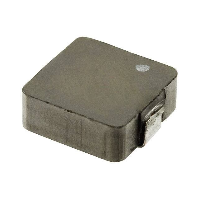
Large-Current Power Inductors MPC
Overview
The KEMET MPC metal composite inductors are designed
for use in power supplies with high ripple current. These
inductors offer a superior saturation current when
compared to technologies based on ferrite cores. Their
low height makes them ideal in applications with thin
profile requirements.
Also, the flat wire used in the design of the MPC enables
high ripple current carrying capabilities.
Applications
•
•
•
•
•
•
Switching DC-DC power supplies
Notebook computers
Tablets
Embedded computer systems
HDTVs
DVD and BluRay players
Part Number System
MPC
0740
L
R42C
Series
Size Code
Inductor
Inductance Code µH
MPC
0730
0740
0750
1040
1055
1250
R = decimal point
Examples:
R42C = 0.42 µH
1R0C = 1.0 µH
One world. One KEMET
© KEMET Electronics Corporation • KEMET Tower • One East Broward Boulevard�
Fort Lauderdale, FL 33301 USA • 954-766-2800 • www.kemet.com
L9001_MPC • 9/11/2018
1
�NOT FOR NEW DESIGN
SMD Inductors
Large-Current Power Inductors MPC
Table 1 – Ratings & Part Number Reference
1
2
Rated Current (A)
Part Number
Inductance (µH)
at 100 kHz
Inductance
Tolerance
DC Resistance
(mΩ) ±10%
Irms1 (Ref.)
Isat2 (Ref.)
MPC0730LR20C
0.20
±25%
1.20
23.0
17.5
20.0
MPC0740LR42C
0.42
±20%
1.55
22.0
MPC0750LR60C
0.60
±20%
2.30
17.0
19.0
MPC0750LR68C
0.68
±20%
2.20
18.0
16.0
30.0
MPC1040LR36C
0.36
±20%
1.05
25.5
MPC1040LR45C
0.45
±20%
1.10
25.0
27.0
MPC1040LR56C
0.56
±20%
1.30
23.0
25.0
MPC1040LR88C
0.88
±20%
2.30
17.0
24.0
MPC1055LR36C
0.36
±20%
0.75
32.0
35.0
MPC1055L1R0C
1.00
±20%
2.30
18.5
21.0
MPC1250LR36C
0.36
±20%
0.65
38.0
40.0
MPC1250LR50C
0.50
±20%
0.80
35.0
40.0
T = 40 K rise at rated current.
Inductance drop 20% at rated current.
DC-Superposed Characteristics
70
0.25
0.20
50
40
0.15
30
0.10
20
0.05
0.00
5
10
15
20
25
70
60
0.4
50
40
0.3
30
0.2
20
0
0
10
0
5
10
15
25
30
MPC0750LR68C
0
80
0.8
0.7
70
0.7
70
0.6
60
0.6
60
0.5
50
0.5
50
0.4
40
0.4
40
0.3
30
0.3
30
0.2
20
0.2
20
0.1
10
0.1
10
0
0.0
0
0
5
10
15
20
25
30
Idc (A)
© KEMET Electronics Corporation • KEMET Tower • One East Broward Boulevard�
Fort Lauderdale, FL 33301 USA • 954-766-2800 • www.kemet.com
Inductance (µH)
80
T (ºC)
Inductance (µH)
MPC0750LR60C
20
Idc (A)
DC Current (A)
0.8
80
0.1
10
0
MPC0740LR42C
0.5
60
T (ºC)
Inductance (µH)
0.6
T (ºC)
80
0
5
10
15
20
25
T (ºC)
MPC0730LR20C
Inductance (µH)
0.30
0
DC Current (A)
L9001_MPC • 9/11/2018
2
�NOT FOR NEW DESIGN
SMD Inductors
Large-Current Power Inductors MPC
DC-Superposed Characteristics cont’d
0.7
60
50
0.3
40
0.2
30
20
0.1
Inductance (µH)
0.4
10
15
20
Idc (A)
25
30
MPC1040LR56C
50
40
0.3
30
0.2
20
0.1
0
Inductance (µH)
Inductance (µH)
60
0.4
5
10
15
20
25
30
20
10
0
5
10
15
70
0.8
60
0.7
0.6
50
0.5
40
0.4
30
0.3
0
0
1.4
70
1.2
50
0.3
40
0.2
30
20
0.1
Inductance (µH)
80
60
20
10
0
5
10
15
20
Idc (A)
25
30
35
40
MPC1250LR36C
0.4
0.2
0.6
30
20
0.1
10
5
10
15
20
Idc (A)
0
25
30
35
40
80
70
60
50
40
30
0.4
70
40
MPC1055L1R0C
0.6
0.7
50
0
30
0.8
80
60
0.3
0
25
1.0
0
0
© KEMET Electronics Corporation • KEMET Tower • One East Broward Boulevard�
Fort Lauderdale, FL 33301 USA • 954-766-2800 • www.kemet.com
Inductance (µH)
15
0
∆T (ºC)
Inductance (µH)
0.5
10
20
20
0.2
10
5
0
80
0.1
∆T (ºC)
Inductance (µH)
MPC1055LR36C
0
30
Idc (A)
0.4
0
25
MPC1040LR88C
Idc (A)
0.5
20
Idc (A)
0.2
10
0
30
0.2
0.9
70
0.5
40
0.3
1.0
80
0.6
50
0.4
10
0
5
10
15
20
Idc (A)
0
30
25
MPC1250LR50C
80
70
60
0.5
50
0.4
40
0.3
30
0.2
20
0.1
0
∆T (ºC)
5
60
0.5
0
0
T (ºC)
0.7
0
70
0.1
10
0
80
0.6
T (ºC)
Inductance (µH)
70
MPC1040LR45C
T (ºC)
80
T (ºC)
MPC1040LR36C
∆T (ºC)
0.5
10
0
5
10
15
20
Idc (A)
25
30
35
40
0
L9001_MPC • 9/11/2018
3
�MPC1040LR36C
0.36 ±20%
MPC0750LR60C
0.60
±20%
[RoHS
MPC0750LR60C
0.60±20%
±20%
[RoHS Compliant]
Compliant]
MPC1040LR36C
0.36 ±20%
MPC1040LR36C
0.36
MPC0750LR60C
0.60
MPC1040LR36C
0.36
±20%
MPC1040LR45C
0.45 ±20%
MPC1040LR36C
0.36
±20%
MPC1040LR36C
0.36
±20%
MPC1040LR45C
0.45 ±20%
・ Precautions (see page 80)
MPC1040LR45C
0.45
MPC1040LR36C
0.36±20%
MPC1040LR45C
0.45
±20%
0.56 ±20%
・ MPC1040LR56C
Precautions (see page 80)
MPC1040LR45C
0.45
±20%
MPC1040LR45C
0.45±20%
±20%
MPC1040LR56C
0.56
±20%
MPC1040LR56C
0.56
Inductance
MPC1040LR45C
0.45
MPC1040LR56C
0.56
±20%
MPC1040LR88C
0.88
±20%
MPC1040LR56C
0.56
±20%
Inductance
(μH)
MPC1040LR56C
0.56
±20%
Model
・
Precautions
(see
page
80)
MPC1040LR88C
0.88
±20%
MPC1040LR88C
0.88
±20%
MPC1040LR56C
0.56
MPC1040LR88C
0.88
±20%
(μH)
Model
MPC1055LR36C
0.36
±20%
at 100kHz
MPC1040LR88C
0.88
±20%
MPC1040LR88C
0.88
±20%
MPC1055LR36C
0.36
±20%
Inductance
MPC1055LR36C
0.36
at
100kHz
MPC1040LR88C
0.88±20%
MPC1055LR36C
0.36
±20%
SMD Inductors
MPC0740LR42C
0.42
±20%
MPC1055L1R0C
1.00
±20%
MPC1055LR36C
0.36
±20%
(μH)
Model
MPC1055LR36C
0.36
±20%
MPC0740LR42C
0.42
±20%
MPC1055L1R0C
1.00
±20%
MPC1055L1R0C
1.00
MPC1055LR36C
0.36±20%
MPC1055L1R0C
1.00
±20%
MPC0750LR60C
0.60
±20%
MPC1250LR36C
0.36
±20%
at
100kHz
Large-Current
Power
Inductors
MPC
MPC1055L1R0C
1.00
±20%
MPC1055L1R0C
1.00
±20%
MPC0750LR60C
0.60
±20%
MPC1250LR36C
0.36
±20%
MPC1040LR36C
0.36
±20%
MPC1250LR36C
0.36
MPC1055L1R0C
1.00±20%
MPC1250LR36C
0.36
±20%
MPC0740LR42C
0.42
±20%
MPC1250LR50C
0.50
±20%
MPC1250LR36C
0.36
±20%
MPC1040LR36C
0.36
±20%
MPC1250LR36C
0.36±20%
±20%
MPC1040LR45C
0.45
±20%
MPC1250LR50C
0.50
±20%
MPC1250LR50C
0.50
MPC1250LR36C
0.36
MPC1250LR50C
0.50
±20%
MPC0750LR60C
0.60
±20%
0.45
±20%
MPC1250LR50C
MPC1040LR56C
0.56
±20% current.
*1 T=40K
rise at ratedMPC1040LR45C
current. *2 Inductance
drop 20% at0.50
rated±20%
MPC1250LR50C
0.50
±20%
MPC1040LR36C
0.36
±20%
MPC1250LR50C
0.50
±20%
MPC1040LR56C
0.56
±20%
*1 T=40K
rise
at ratedrange:
current. *2 Inductance
drop
20%
at rated
*1 T=40K
rise
current. *2 Inductance
20%
rated
current.
●Operating
temperature
-20~+120drop
(Include
self
temperat
rise)
MPC1040LR88C
0.88
±20% urecurrent.
*1 T=40K
riseatatrated
rated
current. *2 Inductance
drop
20%atat
rated
current.
1.05 ±10%
2.30
±10%
2.30±10%
±10%
1.05 ±10%
1.05
2.30
1.05
±10%
1.10 ±10%
1.05
±10%
1.05
±10%
1.10 ±10%
1.10
1.05±10%
1.10
±10%
1.30 ±10%
1.10
±10%
1.10±10%
±10%
1.30 ±10%
1.30
1.10
1.30
±10%
2.30 ±10%
DC resistance
1.30
±10%
1.30
±10%
2.30
DC
resistance
2.30
±10%
1.30
2.30
±10%
(mΩ)
typ.±10%
0.75
±10%
2.30
±10%
(mΩ)
typ. ±10%
2.30
±10%
0.75
0.75
±10%
2.30
0.75
±10%
1.55
±10%±10%
2.30
DC
resistance
0.75
±10%
0.75
±10%
1.55
±10%
2.30
±10%
2.30
±10%
0.75
2.30
±10%
(mΩ)
typ. ±10%
2.30
±10%
0.65
2.30
±10%
2.30
±10%
2.30
±10%
0.65
1.05
±10%±10%
0.65
±10%
2.30
0.65
±10%
1.55
±10%
0.80
±10%
0.65
±10%
1.05
±10%
0.65
±10%
1.10
±10%±10%
0.80
0.80
±10%
0.65
0.80
±10%
2.30
±10%
1.10
±10%
0.80
±10%
1.30
±10%
0.80
±10%
1.05
±10%
0.80
±10%
1.30
2.30±10%
±10%
25.5
17.0
17.0 25.5
25.5
17.0
25.5
25.0
25.5
25.5
25.0
25.5 25.0
25.0
23.0
25.0
25.0 23.0
23.0
25.0
23.0
Rated current
17.0
23.0
Rated
current
23.0
*1
Irms
17.0
17.0
23.0
17.0
*1
32.0
Irms
(Ref.)
17.0
17.0 32.0
32.0
17.0
32.0
(Ref.)
Rated current
22.0
18.5
32.0
32.0
*1
Irms
22.0
18.5
32.0 18.5
18.5
17.0
38.0
(Ref.)
18.5
18.5
17.0
25.5
38.0
18.5 38.0
38.0
22.0
35.0
38.0
25.5
38.0
25.0
35.0
35.0
38.0
35.0
17.0
25.0
35.0
23.0
35.0
25.5
35.0
23.0
17.0
19.0
19.0
30.0
19.0
30.0
30.0
30.0
27.0
30.0
27.0
27.0
27.0
25.0
27.0
25.0
(A)
25.0
(A)
25.0
Isat *224.0
25.0
24.0
Isat *224.0
(Ref.)
24.0
24.0
35.0
(Ref.) 35.0
(A)
20.0 35.0
35.0
Isat
20.0 *2
21.0
35.0
21.0
19.0
(Ref.) 21.0
21.0
19.0 40.0
30.0
21.0
40.0
20.0
30.0 40.0
40.0
27.0
40.0
40.0
19.0
27.0 40.0
25.0
40.0
30.0 40.0
NOT FOR NEW DESIGN
3 .3
4.14.1
3 .3
5.9
3 .3
3 .3
4.1
4.14.1
4.1
4.1
5.9
3 .3
5.9
3.3
3.3
5.9
3.3
3.3
3.3
3.3
3.3
5.9
3.3 3.3 3.3
5.9
5.95.9
5.9
3.3
5.9
3.3
5.9
3.3
5.9
3.3
3.3
3.3
3.6
3.63.6
3.6
3.6
3.6
5.9
3.3
5.9
3.3
3.3
3.3
4.1
4.14.1
4.1
4.1
4.14.1
3.3
3.3
3.3
3.63.6
3.3
3.6
4.1
3.3
5.9
3.3 3.3 3.3
5.9
5.9
5.9
3.3
5.9
3.3
5.9
3.3
5.9 5.9 3.3 3.3
4.1
3.3
3.3
3.3
3.3
3.3
3.3
3.6
3.5
±0.5
3.5
±0.5
3.5
3.5
±0.5
3.5
±0.5
3.5±0.5
±0.5 3.5 ±0.5
3.5
±0.5
5.5 Maximum
2.62.6
3 .3
5.9
35.9
3..33
33.3.3
3 .3
4.1
3 .3
3 .3
5.9
5.9
5.9
5.9
5.9 5.9 3 .3
4.1
3.0 ±0.5
(2.1)
(2.1)
(2.1)(2.1) (2.1)
5.5 Maximum (2.1)
(2.1)
Maximum (2.1)
5.5
5.55.5
Maximum
5.5Maximum
Maximum
(2.1)
5.5
5.5Maximum
Maximum
5.5 Maximum
2.62.6
2.6
2.62.6
2.6
2.6
2.6 2.6
2.6
2.6
2.62.6
2.6
2.6
2.6
33..33
33.3.3
33.3.3
4.1
(2.1)
(2.1)
5.5 Maximum
3.3
(2.1)
(2.1)
(2.1)
(2.1)
3.0 ±0.5
3.4
3.3
3.4
3.4 8.6
8.6
3.4
8.6 3.4
3.4
3.6
[Part No]
[Part No]
[Part
No]No]
[Lot No]
[Lot
5.9
[Part
No]
[Lot No]
[Lot No]
3.4
8.6
3.4
3.6
[Lot No]
5.0 Maximum
5.0Maximum
Maximum
5.0
5.0 Maximum
3.3
[mm]
[mm]
3.3
3.6
10.0 ±0.3
5.9
5.9
[Lot No] [Part No]
14.5 Maximum
14.5
14.5 Maximum
14.5 Maximum
Maximum
12.5 ±0.3
5.9
3.0 ±0.5
10.0 ±0.3
[Part[Part
No]No]
[Part[Lot
No]No]
[Lot
No]
10.0 ±0.3
10.0 ±0.3
3.3
3.3
3.3
[mm]
[mm]
[mm]
[mm]
[mm]
3.6
5.5 Maximum
3.3
3.6
3.6
5.5 Maximum
5.5 Maximum
3.6
3.6
11.7 Maximum
[mm]
3.0 ±0.5
11.7 Maximum
11.7 Maximum
[mm]
[mm]
3.0 ±0.5
11.7 Maximum
12.5 ±0.3
12.5 ±0.3
MPC1250LR36C
MPC1250LR50C
12.5 ±0.3
● MPC1250LR36C
● MPC1250LR36C
● MPC1250LR36C
● MPC1250LR36C
● MPC1250LR50C
● MPC1250LR50C
●
MPC1250LR50C
● MPC1250LR50C
2.7
3.0
±0.5
3.0
±0.5
3.0
±0.5
3.0 ±0.5
3.0
±0.5
3.0
±0.5
3.0 ±0.5
(2.1)
[Part
[PartNo]
No]
No]
[Part
[PartNo]
No] [Part
[LotNo]
No]
[Lot
[Part
No]
[Part
No] [PartNo]
[Lot
No]
No]
[Lot
No]
[Part
No] [Lot
[Lot
[LotNo]
No] [Lot No]
[Lot No]
4
MPC1055L1R0C
3.5
(2.1)
(2.1)
(2.1)(2.1) (2.1)
(2.1)
(2.1)
(2.1)
Power Inductors VOL.11
4
4
44
2.7
5.5 Maximum
Power Inductors VOL.11
● MPC1055L1R0C
Power Inductors
VOL.11
4 ● MPC1055L1R0C
Power
Inductors
Power Inductors
VOL.11VOL.11
Power
VOL.11
● MPC1055L1R0C
Power Inductors
Inductors
VOL.11
Power
Inductors
VOL.11
Power
Inductors
VOL.11
4
4
VOL.11 ● MPC1055L1R0C
4
4Power Inductors
2.7
3.0 ±0.5
3.0 ±0.5
MPC1055LR36C
11.7 Maximum
[Lot No]
2.7
3.5
3.3
4.0 Maximum
11.7 Maximum
[Lot
No]
11.7 Maximum
11.7
Maximum
11.7
11.7
Maximum
11.7Maximum
Maximum
11.7
11.7Maximum
Maximum [Part No]
11.7 Maximum
10.0
±0.3
10.0
±0.3
10.0
±0.3
10.0
±0.3
10.0
±0.3
10.0
±0.3
10.0
±0.3
● MPC1055LR36C
● MPC1055LR36C
● MPC1055LR36C
●● MPC1055LR36C
MPC1055LR36C
●● MPC1055LR36C
MPC1055LR36C
● MPC1055LR36C
● MPC1055LR36C
(1.5)
4.0 Maximum
2.7
2.7
4.1
10.0
±0.3
10.0
±0.3
● MPC1055LR36C
[Lot
[LotNo]
No]
[Part
No] [Lot No]
[Lot
[LotNo]
No] [Lot No]
[Lot No] [Part No]
3.5
2.7
3.0 ±0.5
3.0 ±0.5
MPC1040LR88C
2.7
(2.1)
[Part No]
[PartMaximum
No]
11.5
[Lot
No]No]
[Part
[PartNo]
No] [Part
[Lot No]
[Part
No]
[Part
No]
[Part No]
10.0 ±0.3
10.0
±0.3
10.0
±0.3
10.0
±0.3
10.0
±0.3
10.0
±0.3
● MPC1040LR88C
10.0
±0.3
10.0
±0.3
● MPC1040LR88C
● MPC1040LR88C
● MPC1040LR88C
●● MPC1040LR88C
MPC1040LR88C
●● MPC1040LR88C
MPC1040LR88C
●
MPC1040LR88C
● MPC1040LR88C
4.0
Maximum
(0.1)
2.7
3.5 2.72.7 3.5
2.7
2.7 3.5
3.52.7 2.7
2.73.5
2.7
2.7 3.5
3.5 2.7
2.7
2.7
3.5
2.7
[Lot No]
(2.1)
[Part No]
(2.1)
(2.1) (2.1) (2.1)
4.0 Maximum (2.1)
11.5 Maximum
4.0 Maximum
[Lot No]
11.5
Maximum
(2.1)
4.0 Maximum (2.1)
11.5 Maximum 4.0
11.5
4.0Maximum
Maximum
11.5Maximum
Maximum
(2.1)
4.0
11.5
4.0Maximum
Maximum
11.5Maximum
Maximum
4.0 Maximum
11.5 Maximum
4.0 Maximum
11.5 Maximum
10.0 ±0.3
10.0 ±0.3
10.0 ±0.3
● MPC1040LR36C
MPC1040LR56C
MPC1040LR56C
● MPC1040LR45C
● MPC1040LR56C
11.5 No]
Maximum
[Part
No]
[Part
[PartNo]
No] [Part
[Lot[Part
No] No]
[Part
No]
[PartNo]
No] 11.5 Maximum
[Lot
[Lot
No]
[Part
No] [Lot No]
[Lot No]
[Lot
[LotNo]
No]
[Lot No] [Part No]
10.0 ±0.3
10.0 ±0.3
10.0
±0.3
10.0
±0.3
10.0
±0.3
10.0
±0.3
10.0
±0.3
● MPC1040LR36C
●
●● MPC1040LR36C
MPC1040LR36C
● MPC1040LR36C
MPC1040LR45C
●
MPC1040LR36C
MPC1040LR36C
● MPC1040LR36C
●
●●●MPC1040LR45C
MPC1040LR45C
MPC1040LR36C
● MPC1040LR45C
MPC1040LR56C
●
MPC1040LR45C
● MPC1040LR45C
MPC1040LR45C
MPC1040LR36C
● MPC1040LR56C
●
●●MPC1040LR56C
MPC1040LR56C
MPC1040LR45C
●
MPC1040LR36C
● MPC1040LR56C
●● MPC1040LR56C
MPC1040LR56C
MPC1040LR45C
● MPC1040LR56C
● MPC1040LR45C
10.0 ±0.3
10.0 ±0.3
10.0 ±0.3
● MPC0750LR60C
2.7
2.7
2.6
6.7 ±0.36.7 ±0.3
6.7 ±0.3
● MPC0750LR60C
3.5
2.6
6.7
±0.3
6.7
±0.3
6.7
±0.3
6.7
±0.3
6.7
±0.3
MPC0750LR60C● MPC0750LR60C
MPC0750LR68C
6.7 ±0.36.7 ±0.3
6.7 ±0.3
6.76.7
±0.3
±0.3
● MPC0750LR60C
● MPC0740LR42C
● MPC0750LR60C
●● MPC0750LR60C
MPC0750LR60C
●● MPC0750LR60C
MPC0750LR60C
● MPC0750LR60C
3.5
2.7
2.0
±0.3
2.0
±0.3
2.0
±0.3
2.0
±0.3
2.0
±0.3
2.0 ±0.32.0 ±0.3
(1.5)
3.0 Maximum (MPC0730)
(1.5)
(1.5)
[Part No]
(1.5)
8.08.0
Maximum
4.0 Maximum
(MPC0740)
5.0 Maximum
Maximum
(1.5)
[Lot
No]
(1.5)
8.0
Maximum
8.0
5.0 Maximum (1.5)
8.0Maximum
Maximum [Part No] 5.0
5.0Maximum
Maximum
8.0
5.0
8.0Maximum
Maximum
5.0Maximum
Maximum
8.0 Maximum [Lot No]
5.0 Maximum
(1.5)
[Part
No]
[Part No]
[Part
8.0No]
Maximum
[Lot
No]
5.0 Maximum
[PartNo]
No] [Part
[Lot
No]
(1.5)
[Part
No]
[Part
No]
No]
[Lot
No]
[Lot
No]
[Part
No] [Lot
8.0 Maximum
5.0 Maximum
[Lot
[LotNo]
No]
(1.5)
[Part No]
[Lot No]
(0.1)
(1.5)
8.0 Maximum
5.0 Maximum
[Lot No]
(0.1) (1.5)
(0.1)
[Part No]
(0.1)
(1.5)
(1.5)
(0.1)
(1.5)
(0.1)
Maximum
11.5
Maximum
[Lot
No]
(1.5)
(0.1) 4.0
(1.5) (1.5)
(0.1)
4.0
Maximum
4.0
11.5
Maximum
11.5
[Part
No]
4.0Maximum
Maximum
11.5Maximum
Maximum
4.0
11.5
4.0Maximum
Maximum
11.5Maximum
Maximum
[Lot
No]
4.0 Maximum
11.5 Maximum11.5 Maximum4.0 Maximum
(0.1)
(1.5)
2.7
2.7
2.7
2.7
3.53.5
±0.5
±0.5
8.0 Maximum
3.5
3.5
3.5
3.03.0
±0.5
±0.5
4.0 Maximum (MPC0740)
3.0 Maximum (MPC0730)
[Lot
Shape and●Dimensions
Land Pattern
[LotNo]
No]
MPC0740LR42C Recommended
4.0 Maximum (MPC0740)
[Lot No]
● MPC0740LR42C
2.7
2.7
2.7
3.53.5
±0.5
±0.5
6.76.7
±0.3
±0.3
6.7
±0.3
6.7
±0.3
6.7
±0.3
6.7
±0.3
6.7
±0.3
[Part
No]
[Part
No]
[Lot
No]
[Lot
No]
Maximum
[Part
No] [Lot8.0No]
2.02.0
±0.3
±0.3
4.0
4.0Maximum
Maximum(MPC0740)
(MPC0740)
4.0 Maximum (MPC0740)
2.02.0
±0.3
±0.3
8.0
8.0Maximum
Maximum
Land Pattern
3.5 ±0.5
● MPC0740LR42C
● MPC0740LR42C
●● MPC0740LR42C
*1 T=40K rise at rated current. *2 Inductance8.0
drop
20% at rated
current.
MPC0740LR42C
Maximum
MPC0730LR20C
●● MPC0740LR42C
●OperatingShape
temperature
-20~+120 (Include
self temperat
ure rise)
and range:
Dimensions
Recommended
MPC0740LR42C
[Part No]Land Pattern
● MPC0740LR42C
No] Pattern
[Part
[PartNo]
No] [Part
MPC0740LR42C
Shape and Dimensions
Recommended
Land
[Lot No]
3.0 Maximum (MPC0730)
25.0
24.0
27.0
24.0
35.0
25.0
35.0
21.0
24.0
21.0
40.0
35.0
40.0
40.0
21.0
40.0
40.0
40.0
25.0
17.0
32.0
23.0
32.0
18.5
17.0
18.5
38.0
32.0
38.0
35.0
18.5
35.0
38.0
2.7
3.5
2.7
2.7
3.5
3.52.7 2.7
2.73.5 35.0
3.5
±0.5
3.5
±0.5
3.5
±0.5
3.5 ±0.53.5 ±0.5
3.5
±0.5
3.5 ±0.5
Dimensions (mm)
2.0
±0.3
2.0
±0.3
2.0
±0.3
2.0
±0.3
2.0
±0.3
Part Number
1.10
±10%
2.30
0.75±10%
±10%
1.30
±10%
0.75
2.30±10%
±10%
2.30
±10%
2.30
0.65±10%
±10%
0.75
±10%
0.65
0.80±10%
±10%
2.30
±10%
0.80 ±10%
0.65 ±10%
0.80 ±10% 2.7
2.7
2.0 ±0.3
0.45
±20%
current.
ure
rise)
ure
rise) ure rise)
current.
0.88
±20%
0.36
±20%
current.
ure
rise)
0.56
±20%
ure
rise)
0.36
±20%
1.00
±20%
ure
rise)
MPC1040LR88C
0.88
±20%
MPC1055L1R0C
1.00
±20%
MPC1250LR36C
0.36
±20%
Shape and Dimensions
Recommended Land
Pattern
MPC1055LR36C
0.36
±20%
MPC1250LR36C
0.36
±20%
MPC1250LR50C
0.50
±20%
Shape
and Dimensions
Recommended
Land
Pattern
Shape
Dimensions
Recommended
Land
Shapeand
and
Dimensions
Recommended
LandPattern
Pattern
MPC1055L1R0C
1.00
±20%
Shape
and
Dimensions
Recommended
Land
Pattern
(MPC0730)
MPC1250LR50C
0.50
±20%3.0 Maximum
Shapeand
andDimensions
Dimensions
Recommended
Land
Pattern
*1 T=40K rise at rated
current. *2 Inductance drop
20% atPattern
rated
current.
Shape
Recommended
Land
MPC1250LR36C
0.36
±20%
3.0
Maximum
(MPC0730)
3.0
(MPC0730)
3.0Maximum
Maximum
(MPC0730)
4.0
Maximum
●Operating temperature range: -20~+120 (Include self temperat
ure rise) (MPC0740)
Maximum
*1 T=40K rise at rated current. *2 Inductance drop 20% at8.0
rated
current.
3.0
Maximum
(MPC0730)
4.0
Maximum
(MPC0740)
4.0
Maximum
3.0
Maximum
(MPC0730)
MPC1250LR50C
0.50
±20% (MPC0740)
4.0
8.0 Maximum
8.0
Maximum
8.0self
Maximum
3.0 Maximum
Maximum (MPC0740)
(MPC0730)
●Operating temperature range: -20~+120 (Include
temperat
ure rise)
2.0 ±0.32.0 ±0.3
2.0 ±0.3
Dimensions
MPC1040LR45C
*1 T=40K
rise
current. *2 Inductance
20%
rated
●Operating
temperature
range:
-20~+120
(Include
self
temperat
●Operating
temperature
range:
-20~+120
(Include
self
temperat
●Operating
temperature
range:
-20~+120
(Includedrop
self
temperat
*1 T=40K
riseatatrated
rated
current. *2 Inductance
drop
20%atat
rated
MPC1040LR88C
MPC1055LR36C
*1 T=40Ktemperature
rise at rated current. *2 Inductance
drop temperat
20% at rated
●Operating
(Include
MPC1040LR56C
●Operating temperaturerange:
range: -20~+120
-20~+120
(Includeself
self temperat
MPC1055LR36C
MPC1055L1R0C
●Operating temperature range: -20~+120
(Include self temperat
30.0
30.0
27.0
27.0
25.0
25.0
24.0
24.0
35.0
35.0
21.0
21.0
40.0
40.0
40.0
40.0
(2.2)
(2.2)
(2.2)
Operating temperature range: −20°C to +120°C (Include self temperature rise)
© KEMET Electronics Corporation • KEMET Tower • One East Broward Boulevard�
Fort Lauderdale, FL 33301 USA • 954-766-2800 • www.kemet.com
(2.2)
L9001_MPC • 9/11/2018
4
�NOT FOR NEW DESIGN
SMD Inductors
Large-Current Power Inductors MPC
Taping Specification
MPC0740, 0750 Series
(1,000pcs./reel)
Dimensions of indented square hole plastic tape
øD0
W
F
P2
E
P0
T
P1
Reel dimensions
Case
Size
Dimensions (mm)
Reel
Quantity
W
MPC0740, 0750 Series
F
E
P1
P2
P0
øD0
T
±0.1
±0.1
±0.1
±0.1
±0.1
±0.05
±0.05
7.5
1.75
12.0
2.0
4.0
1.55
0.4
W1
(1,000pcs./reel)
A
B
CTolerance
MPC0730
±0.2
E
D
MPC0740
1,000
Dimensions of indented square hole
plastic
tape
Nominal
16.0
MPC0750
øD0
P0Tolerance
P2
±0.3
24.0
±0.1
11.5
±0.1
1.75
±0.1
16.0
±0.1
2.0
±0.1
4.0
±0.05
1.55
±0.05
0.4
500
Tolerance
Nominal
W2
±0.2
24.0
±0.1
11.5
±0.1
1.75
±0.1
24.0
±0.1
2.0
±0.1
4.0
±0.05
1.55
±0.05
0.4
500
Tolerance
Nominal
±0.4
24.0
±0.2
11.5
±0.2
1.75
±0.2
24.0
±0.2
2.0
±0.2
4.0
±0.02
1.5
±0.1
0.4
MPC1055
MPC1250
F
500
E
Nominal
MPC1040
W
T
P1
Reel Specifications
Reel dimensions
E
C
D
A
B
W1
W2
Dimensions (mm)
Case
Size
A
B
C
D
E
Tolerance
±2.0
±1.0
±0.2
±0.8
±0.5
Nominal
ø330
ø80
ø13.0
ø21.0
2.0
MPC1040
Tolerance
Nominal
±5.0
ø330
±5.0
ø80
±0.5
ø13.5
±1.0
ø21.0
±0.5
2.0
MPC1055
Tolerance
Nominal
±2.0
ø380
±1.0
ø100
±0.5
ø13.0
±0.8
ø21.0
MPC1250
Tolerance
Nominal
±2.0
ø380
±5.0
ø100
±0.5
ø13.0
±0.8
ø21.0
MPC0730
MPC0740
MPC0750
W1
W2
±1.0
±1.0
R1.0
17.5
21.5
R1.0
±2.0
24.4
±3.0
30.4
±0.5
2.0
R1.0
±2.0
24.4
±3.0
30.4
±0.5
2.0
R1.0
±2.0
25.5
±3.0
28.5
© KEMET Electronics Corporation • KEMET Tower • One East Broward Boulevard�
Fort Lauderdale, FL 33301 USA • 954-766-2800 • www.kemet.com
r
L9001_MPC • 9/11/2018
5
�SMD Inductors
NOT FOR NEW DESIGN
Large-Current Power Inductors MPC
Handling Precautions
Inductors should be stored in normal working environments. While the inductors themselves are quite robust in other
environments, solderability will be degraded by exposure to high temperatures, high humidity, corrosive atmospheres, and
long term storage.
KEMET recommends that maximum storage temperature not exceed 40°C and maximum storage humidity not exceed 70%
relative humidity. Atmospheres should be free of chlorine and sulfur bearing compounds. Temperature fluctuations should
be minimized to avoid condensation on the parts. For optimized solderability, inductors’ stock should be used promptly,
preferably within six months of receipt.
Export Control
For customers in Japan
For products which are controlled items subject to the “Foreign Exchange and Foreign Trade Law” of Japan, the export
license specified by the law is required for export.
For customers outside Japan
Inductors should not be used or sold for use in the development, production, stockpiling or utilization of any conventional
weapons or mass-destruction weapons (nuclear, chemical, biological weapons or missiles), or any other weapons.
© KEMET Electronics Corporation • KEMET Tower • One East Broward Boulevard�
Fort Lauderdale, FL 33301 USA • 954-766-2800 • www.kemet.com
L9001_MPC • 9/11/2018
6
�SMD Inductors
NOT FOR NEW DESIGN
Large-Current Power Inductors MPC
KEMET Electronics Corporation Sales Offices
For a complete list of our global sales offices, please visit www.kemet.com/sales.
Disclaimer
All product specifications, statements, information and data (collectively, the “Information”) in this datasheet are subject to change. The customer is responsible for
checking and verifying the extent to which the Information contained in this publication is applicable to an order at the time the order is placed. All Information given
herein is believed to be accurate and reliable, but it is presented without guarantee, warranty, or responsibility of any kind, expressed or implied.
Statements of suitability for certain applications are based on KEMET Electronics Corporation’s (“KEMET”) knowledge of typical operating conditions for such
applications, but are not intended to constitute – and KEMET specifically disclaims – any warranty concerning suitability for a specific customer application or use.
The Information is intended for use only by customers who have the requisite experience and capability to determine the correct products for their application. Any
technical advice inferred from this Information or otherwise provided by KEMET with reference to the use of KEMET’s products is given gratis, and KEMET assumes
no obligation or liability for the advice given or results obtained.
Although KEMET designs and manufactures its products to the most stringent quality and safety standards, given the current state of the art, isolated component
failures may still occur. Accordingly, customer applications which require a high degree of reliability or safety should employ suitable designs or other safeguards
(such as installation of protective circuitry or redundancies) in order to ensure that the failure of an electrical component does not result in a risk of personal injury
or property damage.
Although all product–related warnings, cautions and notes must be observed, the customer should not assume that all safety measures are indicted or that other
measures may not be required.
KEMET is a registered trademark of KEMET Electronics Corporation.
© KEMET Electronics Corporation • KEMET Tower • One East Broward Boulevard�
Fort Lauderdale, FL 33301 USA • 954-766-2800 • www.kemet.com
L9001_MPC • 9/11/2018
7
�
很抱歉,暂时无法提供与“MPC1040LR88C”相匹配的价格&库存,您可以联系我们找货
免费人工找货- 国内价格 香港价格
- 500+7.73219500+0.96483


 工商网监
湘ICP备2023018690号
工商网监
湘ICP备2023018690号
