Axial Aluminum Electrolytic Capacitors
PEG226, +150°C
Overview
Applications
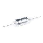
The KEMET PEG226 is an electrolytic capacitor with an
outstanding electrical performance. The device has a
polarized all-welded design, tinned copper wire leads,
and a negative pole connected to the case. The PEG226
winding is housed in a cylindrical aluminum can, with a high
purity aluminum lid and a high quality rubber gasket. The
low ESR is the result of a low resistive electrolyte/paper
system and an all-welded design. Thanks to its mechanical
robustness, the PEG226 is suitable for use in mobile
and aircraft installations, with operation up to +150°C.
KEMET's automotive grade capacitors meet the demanding
Automotive Electronics Council's AEC–Q200 qualification
requirements.
The KEMET PEG226 is a new generation of high
performance axial electrolytic capacitors. It is designed for
automotive applications with extremely high demands.
Benefits
• AEC–Q200 automotive qualified
• 2,000 hours at +150°C
• Extremely high ripple current
• Up to 28 ARMS ripple current, continuous load
• High vibration resistance
• Polarized all-welded design
• Outstanding electrical performance
Click image above for interactive 3D content
Open PDF in Adobe Reader for full functionality
Part Number System
PEG226
H
F
415
0
M
E1
Series
Rated Voltage (VDC)
Size Code
Capacitance Code
(µF)
Version
Capacitance
Tolerance
Packaging
Axial Aluminum
Electrolytic
H = 25
K = 40
M = 63
N = 80
See Dimension
Table
The last two
digits represent
significant figures.
The first digit
indicates the total
number digits.
0 = Standard
Q = −10/+30%
M = ±20%
E1 = Bulk
Built Into Tomorrow
© KEMET Electronics Corporation • KEMET Tower • One East Broward Boulevard�
Fort Lauderdale, FL 33301 USA • 954-766-2800 • www.kemet.com
A4016_PEG226 • 9/2/2020
1
�Axial Aluminum Electrolytic Capacitors – PEG226, +150°C
Performance Characteristics
Item
Performance Characteristics
Capacitance Range
Rated Voltage
250 – 4,700 µF
25 – 80 VDC
Operating Temperature
–40 to +150°C
Capacitance Tolerance
−10/+30%, (±20% select values) at 100 Hz/+20°C
Operational Lifetime
Shelf Life
Leakage Current
Vibration Test
Specifications
Standards
D (mm)
Rated voltage, +125°C (hours)
Rated voltage, +150°C (hours)
16
6,300
1,500
18 and 20
8,400
2,000
5,000 hours at +105°C or 10 years at +40°C 0 VDC
I = 0.003 CV + 4.0 (µA)
C = rated capacitance (µF), V = rated voltage (VDC). Voltage applied for 5 minutes at +20°C.
Procedure
Requirements
1.5 mm displacement amplitude or 20 g maximum acceleration. Vibration applied
for three 22-hour sessions at 10 – 2,000 Hz (capacitor clamped by body).
No leakage of electrolyte or
other visible damage. Deviations
in capacitance from initial
measurements must not exceed:
Δ C/C < 5%
IEC 60384–4 long life grade 40/125/56, AEC–Q200
Compensation Factor of Ripple Current (RC) vs. Frequency
Frequency
100 Hz
300 Hz
1 kHz
5 kHz
100 kHz
Coefficient
0.35
0.57
0.80
1.00
1.04
Test Method & Performance
Endurance Life Test
Conditions
Performance
Temperature
Test Duration
Ripple Current
Voltage
Performance
Capacitance Change
Equivalent Series Resistance
Leakage Current
+150°C
1,500 hours (D = 16 mm)
2,000 hours (D = 18 and 20 mm)
Maximum ripple current specified in table
The sum of DC voltage and the peak AC voltage must not exceed the rated voltage of the capacitor
The following specifications will be satisfied when the capacitor is tested at +20°C:
Within 15% of the initial value
Does not exceed 200% of the initial value
Does not exceed leakage current limit
© KEMET Electronics Corporation • KEMET Tower • One East Broward Boulevard�
Fort Lauderdale, FL 33301 USA • 954-766-2800 • www.kemet.com
A4016_PEG226 • 9/2/2020
2
�Axial Aluminum Electrolytic Capacitors – PEG226, +150°C
Ordering Options Table
Packaging Kind
Lead and
Packaging Code
Lead Length (mm)
Standard Packaging Option
Bulk (box)
40 ±2
(E1)
Dimensions – Millimeters
END VIEW (+)
SIDE VIEW
LL
D
LL
−
+
d
L
L1
Length to Lead Bend
Size
Code
F
D
L
Dimensions in mm
L1
d
LL
±0.5
±1
Minimum
±0.03
b ±2 Box
Approximate
Weight
Grams
16.2
26.7
33
1.0
40
8
G
16.2
34.7
41
1.0
40
11
M
18.2
26.7
33
1.0
40
11
N
18.2
34.7
41
1.0
40
14
V
18.2
38.7
45
1.0
40
16
H
20.2
26.7
33
1.0
40
13
J
20.2
34.7
41
1.0
40
20
L
20.2
42.7
49
1.0
40
24
Note: L1 is KEMET's recommendation for minimum distance between symmetrical lead bend. Available only for
customer specific part numbers. Lead bend dimensions must be specified and confirmed per article.
© KEMET Electronics Corporation • KEMET Tower • One East Broward Boulevard�
Fort Lauderdale, FL 33301 USA • 954-766-2800 • www.kemet.com
A4016_PEG226 • 9/2/2020
3
�Axial Aluminum Electrolytic Capacitors – PEG226, +150°C
Shelf Life
The capacitance, ESR and impedance of a capacitor will not change significantly after extended storage periods, however,
the leakage current will very slowly increase. KEMET products are particularly stable and allow a shelf life in excess of ten
years at 40°C. See sectional specification under each product for specific data.
Failure Rate
Estimated field failure rate: ≤ 0.15 ppm (failures per year/produced number of capacitors per year).
The expected failure rate for this capacitor range is based on field experience for capacitors with structural similarity.
Environmental Compliance
All Part Numbers in this datasheet are Reach and RoHS compliant and Halogen-Free.
As an environmentally conscious company, KEMET is working continuously with improvements concerning the environmental
effects of both our capacitors and their production.
In Europe (RoHS Directive) and in some other geographical areas such as China, legislation has been put in place to prevent
the use of some hazardous materials, such as lead (Pb), in electronic equipment. All products in this catalog are produced
to help our customers' obligations to guarantee their products and fulfill these legislative requirements. The only material of
concern in our products has been lead (Pb), which has been removed from all designs to fulfill the requirement of containing
less than 0.1% of lead in any homogeneous material. KEMET will closely follow any changes in legislation worldwide and
make any necessary changes in its products, whenever needed.
Some customer segments such as medical, military and automotive electronics may still require the use of lead in electrode
coatings. To clarify the situation and distinguish products from each other, a special symbol is used on the packaging labels
for RoHS compatible capacitors.
Due to customer requirements, there may appear additional markings such as lead-free (LF), or lead-free wires (LFW) on the
label.
© KEMET Electronics Corporation • KEMET Tower • One East Broward Boulevard�
Fort Lauderdale, FL 33301 USA • 954-766-2800 • www.kemet.com
A4016_PEG226 • 9/2/2020
4
�Axial Aluminum Electrolytic Capacitors – PEG226, +150°C
Table 1 – Ratings & Part Number Reference
VDC
Rated
Capacitance
100 Hz
20°C (µF)
1
Size
Code
Ripple Current
Case
Size
DxL
(mm)
25
25
25
25
25
25
25
25
40
40
40
40
40
40
40
40
63
63
63
63
63
63
63
63
80
80
80
80
80
80
80
80
1500
2200
2000
3000
3400
2200
3300
4700
800
1200
1200
1800
2000
1500
2200
2700
250
370
380
560
640
470
680
900
250
370
380
560
640
470
680
900
F
G
M
N
V
H
J
L
F
G
M
N
V
H
J
L
F
G
M
N
V
H
J
L
F
G
M
N
V
H
J
L
16 x 27
16 x 35
18 x 27
18 x 35
18 x 39
20 x 27
20 x 35
20 x 43
16 x 27
16 x 35
18 x 27
18 x 35
18 x 39
20 x 27
20 x 35
20 x 43
16 x 27
16 x 35
18 x 27
18 x 35
18 x 39
20 x 27
20 x 35
20 x 43
16 x 27
16 x 35
18 x 27
18 x 35
18 x 39
20 x 27
20 x 35
20 x 43
VDC
Rated
Capacitance
Size
Code
Case
Size
Maximum
Rated
≥ 5 kHz
≥ 5 kHz
≥ 5 kHz
≥ 5 kHz
≥ 5 kHz
125°C (A)1 140°C (A)1 150°C (A)1 125°C (A) 125°C (A)
16.8
19.2
18.8
21.2
22.0
22.2
25.8
28.5
16.2
18.6
18.3
20.5
21.4
22.8
25.7
27.9
11.5
13.6
14.0
16.2
17.1
17.3
20.0
22.2
9.9
12.0
12.2
14.3
15.0
15.4
18.1
20.3
10.6
12.1
11.9
13.4
13.9
14.0
16.3
18.0
10.2
11.8
11.6
13.0
13.6
14.4
16.2
17.6
7.3
8.6
8.9
10.2
10.8
10.9
12.7
14.0
6.3
7.6
7.7
9.0
9.5
9.8
11.4
12.8
4.7
5.4
5.3
6.0
6.2
6.3
7.3
8.1
4.6
5.3
5.2
5.8
6.1
6.5
7.3
7.9
3.3
3.9
4.0
4.6
4.8
4.9
5.7
6.3
2.8
3.4
3.4
4.0
4.2
4.4
5.1
5.7
5.9
7.2
6.5
7.9
8.3
7.1
8.9
10.3
5.6
7.0
6.3
7.6
8.1
7.3
8.9
10.1
4.0
5.1
4.9
6.0
6.5
5.5
6.9
8.1
3.4
4.4
4.3
5.4
5.9
4.9
6.3
7.4
Ripple Current
ESR Maximum
Maximum
7.4
9.1
8.3
10.0
10.5
9.1
11.3
13.1
7.2
8.8
8.0
9.6
10.3
9.3
11.2
12.8
5.1
6.4
6.1
7.6
8.2
7.0
8.7
10.2
4.4
5.7
5.5
6.9
7.5
6.4
8.0
9.4
100 Hz
20°C (mΩ)
72
51
53
37
33
50
34
25
100
69
70
49
43
57
41
32
227
155
151
104
91
125
87
67
279
190
187
128
113
152
106
81
5 – 100 kHz
100 kHz
125 – 150°C
20°C (mΩ)
(mΩ)
36
12.7
26
9.7
26
11.0
19
8.7
17
8.1
25
10.6
17
7.8
13
6.4
36
13.6
26
10.3
27
11.7
20
9.3
17
8.5
22
10.0
17
7.9
13
6.7
53
26.9
37
19.2
36
19.9
26
14.9
23
13.3
32
17.5
23
13.0
18
10.6
105
36.3
72
25.0
72
26.3
50
19.2
45
17.4
60
21.9
42
15.9
32
12.7
ESR
Part Number
PEG226HF4150ME1
PEG226HG4220ME1
PEG226HM4200QE1
PEG226HN4300QE1
PEG226HV4340QE1
PEG226HH4220QE1
PEG226HJ4330QE1
PEG226HL4470QE1
PEG226KF3800QE1
PEG226KG4120QE1
PEG226KM4120QE1
PEG226KN4180QE1
PEG226KV4200QE1
PEG226KH4150QE1
PEG226KJ4220QE1
PEG226KL4270QE1
PEG226MF3250QE1
PEG226MG3370QE1
PEG226MM3380QE1
PEG226MN3560QE1
PEG226MV3640QE1
PEG226MH3470QE1
PEG226MJ3680QE1
PEG226ML3900QE1
PEG226NF3250QE1
PEG226NG3370QE1
PEG226NM3380QE1
PEG226NN3560QE1
PEG226NV3640QE1
PEG226NH3470QE1
PEG226NJ3680QE1
PEG226NL3900QE1
Part Number
Capacitor-mounted with low thermal resistance path (heat-sink).
© KEMET Electronics Corporation • KEMET Tower • One East Broward Boulevard�
Fort Lauderdale, FL 33301 USA • 954-766-2800 • www.kemet.com
A4016_PEG226 • 9/2/2020
5
�Axial Aluminum Electrolytic Capacitors – PEG226, +150°C
Marking
KEMET logo, Polarity indication
Part number
Batch number
prefixed by week and
year of manufacture
Capacitance, Rated voltage (VDC)
Construction
Tinned Copper
Wire Lead (−)
Aluminum Can
Welded
Terminal Tab (+)
High Purity
Aluminum Lid
Tinned Copper
Wire Lead (+)
Rubber Gasket
Detailed Cross Section
High Purity
Aluminum Lid
Welded Terminal
Tab (+)
Margin
Aluminum Can
Paper Spacer Impregnated
with Electrolyte
(First Layer)
Cathode Aluminum Foil,
Etched (Second Layer)
Tinned Copper
Paper Spacer Impregnated
Wire Lead (+)
with Electrolyte
Anode Aluminum Foil, Etched,
(Third Layer)
Covered with Aluminum Oxide
(Fourth Layer)
Rubber Gasket
© KEMET Electronics Corporation • KEMET Tower • One East Broward Boulevard�
Fort Lauderdale, FL 33301 USA • 954-766-2800 • www.kemet.com
Welded
Terminal Tab (−)
Extended Cathode
Tinned Copper
Wire Lead (−)
A4016_PEG226 • 9/2/2020
6
�Axial Aluminum Electrolytic Capacitors – PEG226, +150°C
Construction Data
The manufacturing process begins with the anode foil being
electrochemically etched to increase the surface area and
then “formed” to produce the aluminum oxide layer. Both the
anode and cathode foils are then interleaved with absorbent
paper and wound into a cylinder. During the winding process,
aluminum tabs are attached to each foil to provide the
electrical contact.
The winding is assembled to the capacitor Al-can and to
the Al-lid. The can is filled with electrolyte and the winding
is impregnated during a vacuum treatment. The capacitor
is sealed. Throughout the process, all materials inside the
housing must be maintained at the highest purity and be
compatible with the electrolyte.
Each capacitor is aged and tested before being packed. The
purpose of aging is to repair any damage in the oxide layer
and thus reduce the leakage current to a very low level. Aging
is carried out at elevated temperature and is accomplished by
applying voltage to the device while carefully controlling the
supply current. The process takes between 2 and 20 hours,
depending on voltage rating.
Damage to the oxide layer can occur due to a variety of
reasons:
• Slitting of the anode foil after forming
• Attaching the tabs to the anode foil
• Minor mechanical damage caused during winding
The following tests are applied for each individual capacitor.
Electrical:
• Leakage current
• Capacitance
• ESR
• Tan Delta
Mechanical/Visual:
• Pull strength test of wire terminals
• Print detail
• Box labels
• Packaging, including packed quantity
© KEMET Electronics Corporation • KEMET Tower • One East Broward Boulevard�
Fort Lauderdale, FL 33301 USA • 954-766-2800 • www.kemet.com
Extended cathode
Anode foil
Foil tab
Tissues
Cathode foil
Etching
Forming
Winding
Assembly
Filling (elyt)
Impregnation
Sealing
Aging
Testing
Labeling
Packing
A4016_PEG226 • 9/2/2020
7
�Axial Aluminum Electrolytic Capacitors – PEG226, +150°C
KEMET Electronics Corporation Sales Offices
For a complete list of our global sales offi ces, please visit www.kemet.com/sales.
Disclaimer
All product specifi cations, statements, information and data (collectively, the “Information”) in this datasheet are subject to change. The customer is responsible for
checking and verifying the extent to which the Information contained in this publication is applicable to an order at the time the order is placed. All Information given
herein is believed to be accurate and reliable, but it is presented without guarantee, warranty, or responsibility of any kind, expressed or implied.
Statements of suitability for certain applications are based on KEMET Electronics Corporation’s (“KEMET”) knowledge of typical operating conditions for such
applications, but are not intended to constitute – and KEMET specifi cally disclaims – any warranty concerning suitability for a specifi c customer application or use.
The Information is intended for use only by customers who have the requisite experience and capability to determine the correct products for their application. Any
technical advice inferred from this Information or otherwise provided by KEMET with reference to the use of KEMET’s products is given gratis, and KEMET assumes
no obligation or liability for the advice given or results obtained.
Although KEMET designs and manufactures its products to the most stringent quality and safety standards, given the current state of the art, isolated component
failures may still occur. Accordingly, customer applications which require a high degree of reliability or safety should employ suitable designs or other safeguards
(such as installation of protective circuitry or redundancies) in order to ensure that the failure of an electrical component does not result in a risk of personal injury
or property damage.
Although all product–related warnings, cautions and notes must be observed, the customer should not assume that all safety measures are indicted or that other
measures may not be required.
KEMET is a registered trademark of KEMET Electronics Corporation.
© KEMET Electronics Corporation • KEMET Tower • One East Broward Boulevard�
Fort Lauderdale, FL 33301 USA • 954-766-2800 • www.kemet.com
A4016_PEG226 • 9/2/2020
8
�