AC Line EMI Suppression and RC Networks
PME295, Metallized Impregnated Paper,
Class Y1, 440 VAC/480 VAC
Overview
Applications
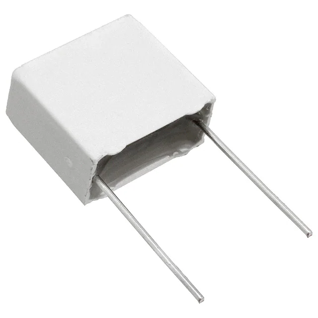
The PME295 is constructed of multilayer metallized paper
encapsulated and impregnated in self-extinguishing
material, meeting the requirements of UL 94 V–0.
Safety capacitors for bridging of double or reinforced
insulation applications, requiring voltage testing up to 4,000
VAC at 60 seconds. PME295 capacitors can be left in place
during this test.
Benefits
• Approvals: ENEC, UL, cUL, CQC
• Rated voltage: 440 VAC/480 VAC 50/60 Hz
• Capacitance range: 470 – 4,700 pF
• Lead spacing: 15.0 mm
• Capacitance tolerance: ±20%
• Climatic category: 40/115/56/B, IEC 60068–1
• Tape & Reel packaging in accordance with IEC 60286–2
• RoHS Compliant and lead-free terminations
• Operating temperature range of −40˚C to +115˚C
• 100% screening factory test at 4,000 VAC, 50 Hz,
2 seconds
Click image above for interactive 3D content
Open PDF in Adobe Reader for full functionality
Legacy Part Number System
PME295
R
B
3470
M
R30
Series
Rated Voltage (VAC)
Lead Spacing (mm)
Capacitance Code (pF)
Capacitance
Tolerance
Packaging
Y1, Metallized Paper
R = 440
B = 15.0
The last three digits
represent significant
figures. The first digit
specifies the total
number of digits.
M = ±20%
See Ordering
Options Table
New KEMET Part Number System
P
295
B
E
471
M
440
A
Capacitor
Class
Series
Lead Spacing (mm)
Size Code
Capacitance Code (pF)
Capacitance
Tolerance
Rated Voltage
(VAC)
Packaging
Y1,
Metallized
Paper
B = 15.0
See
Dimension
Table
First two digits represent
significant figures. Third
digit specifies number of
zeros.
M = ±20%
440 = 440
P = Paper
See Ordering
Options Table
One world. One KEMET
© KEMET Electronics Corporation • KEMET Tower • One East Broward Boulevard�
Fort Lauderdale, FL 33301 USA • 954-766-2800 • www.kemet.com
F3064_PME295_Y1_440-480 • 3/15/2019
1
�Film Capacitors
AC Line EMI Suppression and RC Networks – PME295, Metallized Impregnated Paper, Class Y1, 440 VAC/480 VAC
Benefits cont'd
• Highest possible safety regarding active and passive
• High dV/dt capability
flammability
• Impregnated paper provides excellent stability and
• Excellent self-healing properties ensure long life even when reliability properties, particularly in applications with
subjected to frequent over voltages
continuous operation
• Good resistance to ionization due to impregnated dielectric
Ordering Options Table
Lead
Spacing
Nominal
(mm)
Type of Leads and Packaging
Lead Length
(mm)
KEMET
Lead and
Packaging
Code
Legacy
Lead and
Packaging
Code
6 +0/−1
30 +5/−0
C
A
R06
R30
H0 = 18.5 ±0.5
L
R19T0
H0 = 18.5 ±0.5
XLTF1
R25X2
Standard Lead and Packaging Options
Bulk (Bag) – Short leads
Bulk (Bag) – Maximum length leads
Tape & Reel
(Standard reel Φ = 360 mm)
Tape & Reel
(Standard reel Φ = 360 mm)
15
Native 15
formed to 7.5
Dimensions – Millimeters
FRONT VIEW
SIDE VIEW
L
B
H
d
0.5
LL
p
p
B
H
L
d
Nominal Tolerance Nominal Tolerance Nominal Tolerance Nominal Tolerance Nominal Tolerance
15
15
15
15
±0.4
±0.4
±0.4
±0.4
5.5
6.5
7.5
8.5
Maximum
Maximum
Maximum
Maximum
12.5
12.5
14.5
16
Maximum
Maximum
Maximum
Maximum
18
18
18
18
Maximum
Maximum
Maximum
Maximum
0.8
0.8
0.8
0.8
±0.05
±0.05
±0.05
±0.05
Note: See Ordering Options Table for lead length (LL) options.
© KEMET Electronics Corporation • KEMET Tower • One East Broward Boulevard�
Fort Lauderdale, FL 33301 USA • 954-766-2800 • www.kemet.com
F3064_PME295_Y1_440-480 • 3/15/2019
2
�Film Capacitors
AC Line EMI Suppression and RC Networks – PME295, Metallized Impregnated Paper, Class Y1, 440 VAC/480 VAC
Performance Characteristics
Rated Voltage
Capacitance Range
Capacitance Tolerance
Temperature Range
Climatic Category
Approvals
440 VAC 50/60 Hz (ENEC)
480 VAC 50/60 Hz (UL, cUL)
0.00047 – 0.0047 µF
±20%
−40°C to +115°C
40/115/56/B
ENEC, UL, cUL, CQC
Maximum Values at +23°C
Dissipation Factor
Test Voltage Between Terminals
1 kHz
1.3%
The 100% screening factory test is carried out at 4,000 VAC,
50 Hz, 2 seconds. The voltage level is selected to meet the
requirements in applicable equipment standards. All electrical
characteristics are checked after the test.
Measured at 500 VDC after 60 seconds, +23°C
Insulation Resistance
Between Terminals:
12,000 MΩ
In DC Applications
Resonance Frequency
Recommended voltage ≤ 1,500 VDC
Tabulated self-resonance frequencies f0 refer to 5 mm lead
length
Suppression vs. Frequency, Typical Values
dB
Attenuation
70
60
50
4,700 pF
1,500 pF
470 pF
40
30
20
10
0
f
1
3
5
10
30
100
200 MHz
© KEMET Electronics Corporation • KEMET Tower • One East Broward Boulevard�
Fort Lauderdale, FL 33301 USA • 954-766-2800 • www.kemet.com
F3064_PME295_Y1_440-480 • 3/15/2019
3
�Film Capacitors
AC Line EMI Suppression and RC Networks – PME295, Metallized Impregnated Paper, Class Y1, 440 VAC/480 VAC
Environmental Test Data
Test
IEC Publication
Endurance
IEC 60384-14
IEC 60068-2-6
Test Fc
IEC 60068-2-29
Test Eb
IEC 60068-2-14
Test Na
Vibration
Bump
Change of Temperature
Procedure
1.7 x VR Vac 50 Hz, once every hour increase to 1,000 VAC for 0.1
second, 1,000 hours at upper rated temperature.
3 directions at 2 hours each
10 – 500 Hz at 0.75 mm or 98 m/s2
4,000 bumps at 390 m/s2
Upper and lower rated temperature 5 cycles
Passive Flammability
IEC 60384-14
IEC 60384-1, IEC 60695-11-5 Needle flame test
Humidity
IEC 60068-2-3
Test Ca
+40°C and 93% RH, 56 days
Approvals
Certification Body
Mark
Intertek Semko AB
UL
Specification
File Number
EN/IEC 60384–14 (440
VAC)
SE/0140–13D
UL 60384–14
CAN/CSA–E60384–14:09
CQC
IEC 60384–14
E73869
CQC16001145221
Environmental Compliance
All KEMET EMI capacitors are RoHS Compliant.
© KEMET Electronics Corporation • KEMET Tower • One East Broward Boulevard�
Fort Lauderdale, FL 33301 USA • 954-766-2800 • www.kemet.com
F3064_PME295_Y1_440-480 • 3/15/2019
4
�Film Capacitors
AC Line EMI Suppression and RC Networks – PME295, Metallized Impregnated Paper, Class Y1, 440 VAC/480 VAC
Table 1 – Ratings & Part Number Reference
Maximum Dimensions in
mm
B
H
L
Lead
Spacing
(p)
0.00047
0.00056
0.00068
0.00082
0.001
0.0012
0.0015
0.0018
0.0022
0.0025
0.0027
0.0033
0.0039
0.0047
5.5
5.5
5.5
5.5
5.5
6.5
6.5
6.5
6.5
7.5
7.5
7.5
8.5
8.5
12.5
12.5
12.5
12.5
12.5
12.5
12.5
12.5
12.5
14.5
14.5
14.5
16
16
18
18
18
18
18
18
18
18
18
18
18
18
18
18
15
15
15
15
15
15
15
15
15
15
15
15
15
15
64
59
54
49
46
43
40
37
33
31
30
27
24
22
2,000
2,000
2,000
2,000
2,000
2,000
2,000
2,000
2,000
2,000
2,000
2,000
2,000
2,000
P295BE471M440(1)
P295BE561M440(1)
P295BE681M440(1)
P295BE821M440(1)
P295BE102M440(1)
P295BJ122M440(1)
P295BJ152M440(1)
P295BJ182M440(1)
P295BJ222M440(1)
P295BL252M440(1)
P295BL272M440(1)
P295BL332M440(1)
P295BQ392M440(1)
P295BQ472M440(1)
PME295RB3470M(1)
PME295RB3560M(1)
PME295RB3680M(1)
PME295RB3820M(1)
PME295RB4100M(1)
PME295RB4120M(1)
PME295RB4150M(1)
PME295RB4180M(1)
PME295RB4220M(1)
PME295RB4250M(1)
PME295RB4270M(1)
PME295RB4330M(1)
PME295RB4390M(1)
PME295RB4470M(1)
Capacitance
Value (µF)
B (mm)
H (mm)
L (mm)
Lead Spacing
(p)
fo (MHz)
dV/dt
(V/µs)
New KEMET
Part Number
Legacy Part Number
Capacitance
Value (µF)
fo
(MHz)
dV/dt
(V/µs)
New KEMET Part
Number
Legacy Part
Number
(1) Insert ordering code for lead type and packaging. See Ordering Options Table for available options.
© KEMET Electronics Corporation • KEMET Tower • One East Broward Boulevard�
Fort Lauderdale, FL 33301 USA • 954-766-2800 • www.kemet.com
F3064_PME295_Y1_440-480 • 3/15/2019
5
�Film Capacitors
AC Line EMI Suppression and RC Networks – PME295, Metallized Impregnated Paper, Class Y1, 440 VAC/480 VAC
Soldering Process
The implementation of the RoHS directive has resulted in the selection of SnAuCu (SAC) alloys or SnCu alloys as primary
solder. This has increased the liquidus temperature from 183°C for SnPb eutectic alloys to 217 – 221°C for the new alloys.
As a result, the heat stress to the components, even in wave soldering, has increased considerably due to higher preheat and
wave temperatures. Polypropylene capacitors are especially sensitive to heat (the melting point of polypropylene is 160 –
170°C). Wave soldering can be destructive, especially for mechanically small polypropylene capacitors (with lead spacing of
5 to 15 mm), and great care must be taken during soldering. The recommended solder profiles from KEMET should be used.
Consult KEMET with any questions. In general, the wave soldering curve from IEC Publication 61760-1, Edition 2 serves as a
solid guideline for successful soldering. See Figure 1.
Reflow soldering is not recommended for through-hole film capacitors. Exposing capacitors to a soldering profile in excess
of the above the recommended limits may result in degradation of or permanent damage to the capacitors.
Do not place the polypropylene capacitor through an adhesive curing oven to cure resin for surface mount components.
Insert through-hole parts after the curing of surface mount parts. Consult KEMET to discuss the actual temperature profile in
the oven, if through-hole components must pass through the adhesive curing process. A maximum of two soldering cycles is
recommended. Allow time for the capacitor surface temperature to return to normal before the second soldering cycle.
Manual Soldering Recommendations
Wave Soldering Recommendations
300
Following is the recommendation for manual
soldering with a soldering iron.
2 +3 seconds maximum
260°C
250
First wave
Recommended Soldering Temperature
Temperature (°C)
200
400
350
Soldering Iron Bit Temperature (°C)
Second wave
300
Cooling
∆T < 150°C
Preheating
150
ca 2°C/second
ca 3.5°C/second typical
T preheat
100
ca 5°C/second
115 °C max
100 °C
250
Typical
50
200
150
0
0
100
40
80
120
160
200
240
Time (s)
50
0
0
1
2
3
4
5
6
7
8
Soldering Time (seconds)
The soldering iron tip temperature should
be set at 350°C (+10°C maximum) with the
soldering duration not to exceed more than 3
seconds.
© KEMET Electronics Corporation • KEMET Tower • One East Broward Boulevard�
Fort Lauderdale, FL 33301 USA • 954-766-2800 • www.kemet.com
F3064_PME295_Y1_440-480 • 3/15/2019
6
�Film Capacitors
AC Line EMI Suppression and RC Networks – PME295, Metallized Impregnated Paper, Class Y1, 440 VAC/480 VAC
Soldering Process cont'd
Wave Soldering Recommendations cont'd
1. The table indicates the maximum set-up temperature of the soldering process
Figure 1
Dielectric
Film
Material
Maximum Preheat Temperature
Maximum Peak
Soldering Temperature
Capacitor
Capacitor
Capacitor
Capacitor
Capacitor
Pitch ≤ 10 mm Pitch = 15 mm Pitch > 15 mm Pitch ≤ 15 mm Pitch > 15 mm
Polyester
130°C
130°C
130°C
270°C
270°C
Polypropylene
100°C
110°C
130°C
260°C
270°C
Paper
130°C
130°C
140°C
270°C
270°C
Polyphenylene
sulphide
150°C
150°C
160°C
270°C
270°C
2. The maximum temperature measured inside the capacitor: set the temperature so that inside the element the maximum
temperature is below the limit.
Dielectric Film Material
Maximum Temperature
Measured Inside the Element
Polyester
160°C
Polypropylene
110°C
Paper
160°C
Polyphenylene sulphide
160°C
Temperature monitored inside the capacitor.
Selective Soldering Recommendations
Selective dip soldering is a variation of reflow soldering. In this method, the printed circuit board with through-hole
components to be soldered is preheated and transported over the solder bath, as in normal-flow soldering, without touching
the solder. When the board is over the bath, it is stopped. Pre-designed solder pots are lifted from the bath with molten
solder only at the places of the selected components, and then pressed against the lower surface of the board to solder
the components.
The temperature profile for selective soldering is similar to the temperature profile for double-wave flow soldering outlined in
this document. However, instead of two baths, there is only one with a time from 3 to 10 seconds. In selective soldering, the
risk of overheating is greater than in double-wave flow soldering, and great care must be taken so that the parts do
not overheat.
© KEMET Electronics Corporation • KEMET Tower • One East Broward Boulevard�
Fort Lauderdale, FL 33301 USA • 954-766-2800 • www.kemet.com
F3064_PME295_Y1_440-480 • 3/15/2019
7
�Film Capacitors
AC Line EMI Suppression and RC Networks – PME295, Metallized Impregnated Paper, Class Y1, 440 VAC/480 VAC
Construction
Molded Plastic
Case
Metallized
Impregnated Paper
(First Layer)
Detailed Cross Section
Molded Plastic
Case
Self-Extinguishing
Resin
Metallized
Impregnated Paper
(Second Layer)
Margin
Margin
Metal Contact
Layer
Metal Contact
Layer
Margin
Leads
Winding Scheme
Metal
Spraying
Material
Impregnated
Paper
Metallization
Series Design — Multilayer Impregnated Paper Dielectric
2 Section
© KEMET Electronics Corporation • KEMET Tower • One East Broward Boulevard�
Fort Lauderdale, FL 33301 USA • 954-766-2800 • www.kemet.com
F3064_PME295_Y1_440-480 • 3/15/2019
8
�Film Capacitors
AC Line EMI Suppression and RC Networks – PME295, Metallized Impregnated Paper, Class Y1, 440 VAC/480 VAC
Marking
FRONT
TOP
Approval
Marks
Series
Rated Voltage,
Safety Class
IEC Climatic
Category
Capacitance
Capacitance
Tolerance
Manufacturing
Date Code
Approval
Marks
Packaging Quantities
Lead
Spacing
(mm)
Thickness Height
(mm)
(mm)
Length
(mm)
Lead and Packaging Code
15
5.5
7.5
6.5
8.5
12.5
14.5
12.5
16
18.0
18.0
18.0
18.0
Bulk
Short
Leads
Bulk
Long
Leads
Standard
Reel
360 mm
Standard
Reel
Formed
C/R06
1,000
600
600
400
A/R30
500
400
400
250
L/R19T0
600
400
400
400
XLTF1/R25X2
350
400
-
© KEMET Electronics Corporation • KEMET Tower • One East Broward Boulevard�
Fort Lauderdale, FL 33301 USA • 954-766-2800 • www.kemet.com
F3064_PME295_Y1_440-480 • 3/15/2019
9
�Film Capacitors
AC Line EMI Suppression and RC Networks – PME295, Metallized Impregnated Paper, Class Y1, 440 VAC/480 VAC
Lead Taping & Packaging (IEC 60286–2)
Lead Spacing 5 mm
Lead Spacing 7.5 mm
0
0
Lead Spacing 22.5 – 27.5 mm
Lead Spacing 10 – 15mm
0
0
Formed Leads from 10 and 15 mm to 7.5 mm
0
Taping Specification
Standard
IEC 60286-2
Dimensions in mm
Lead spacing
+6/−0.1
F
5
7.5
Formed 7.5
10
15
22.5
27.5
F
±0.5
W
18
18
18
18
18
18
18
18 +1/−0.5
Minimum
W0
5
5
5
5
5
5
5
Position of sprocket hole
±0.5
W1
9
9
9
9
9
9
9
9 +0.75/−0.5
Distance between tapes
Maximum
W2
3
3
3
3
3
3
3
3
Sprocket hole diameter
±0.2
D0
4
4
4
4
4
4
4
4
Feed hole lead spacing
±0.3
P0 (1)
12.7
12.7
12.7 (4)
12.7
12.7
12.7
12.7
12.7
Distance lead – feed hole
±0.7
P1
3.85
3.75
3.75
7.7
5.2
5.3
5.3
P1
Deviation tape – plane
Maximum
∆p
1.3
1.3
1.3
1.3
1.3
1.3
1.3
1.3
Lateral deviation
Maximum
∆h
2
2
2
2
2
2
2
2
0.7
0.9
Maximum
0.9
Maximum
0.9
Maximum
18.5±0.5
18.5±0.5
18.0 +2/−0
58
58
58 Maximum
Carrier tape width
Hold-down tape width
Total thickness
Sprocket hole/cap body
Sprocket hole/
top of cap body
±0.2
t
Nominal
H0 (2)
Maximum
H1 (3)
0.7
0.7
0.7
18.5±0.5 18.5±0.5 18.5±0.5
32
(1) Maximum cumulative feed hole error, 1 mm per 20 parts
(2) 16.5 mm available on request
31
43
0.7
18.5±0.5 18.5±0.5
43
43
(3) Depending on case size
(4) 15 mm available on request
© KEMET Electronics Corporation • KEMET Tower • One East Broward Boulevard�
Fort Lauderdale, FL 33301 USA • 954-766-2800 • www.kemet.com
F3064_PME295_Y1_440-480 • 3/15/2019
10
�Film Capacitors
AC Line EMI Suppression and RC Networks – PME295, Metallized Impregnated Paper, Class Y1, 440 VAC/480 VAC
Lead Taping & Packaging (IEC 60286-2) cont'd
Ammo Specifications
Dimensions (mm)
Series
R4x, R4x+R, R7x, RSB
F5A, F5B, F5D
F6xx, F8xx
PHExxx, PMExxx, PMRxxx,
SMR & PFR
H
W
T
360
340
59
330
330
50
H
T
W
Reel Specifications
Dimensions (mm)
Series
R4x, R4x+R, R7x, RSB
F5A, F5B, F5D
F6xx, F8xx
PHExxx, PMExxx, PMRxxx,
SMR & PFR
D
H
W
355
500
30
25
55 (Max)
360
500
30
46 (Max)
D
H
W
Manufacturing Date Code (IEC–60062)
Y = Year, Z = Month
Year
2010
2011
2012
2013
2014
2015
2016
2017
2018
2019
2020
2021
2022
2023
2024
2025
2026
2027
2028
2029
2030
Code
A
B
C
D
E
F
H
J
K
L
M
N
P
R
S
T
U
V
W
X
A
Month
January
February
March
April
May
June
July
August
September
October
November
December
Code
1
2
3
4
5
6
7
8
9
O
N
D
© KEMET Electronics Corporation • KEMET Tower • One East Broward Boulevard�
Fort Lauderdale, FL 33301 USA • 954-766-2800 • www.kemet.com
F3064_PME295_Y1_440-480 • 3/15/2019
11
�Film Capacitors
AC Line EMI Suppression and RC Networks – PME295, Metallized Impregnated Paper, Class Y1, 440 VAC/480 VAC
KEMET Electronics Corporation Sales Offices
For a complete list of our global sales offi ces, please visit www.kemet.com/sales.
Disclaimer
All product specifi cations, statements, information and data (collectively, the “Information”) in this datasheet are subject to change. The customer is responsible for
checking and verifying the extent to which the Information contained in this publication is applicable to an order at the time the order is placed. All Information given
herein is believed to be accurate and reliable, but it is presented without guarantee, warranty, or responsibility of any kind, expressed or implied.
Statements of suitability for certain applications are based on KEMET Electronics Corporation’s (“KEMET”) knowledge of typical operating conditions for such
applications, but are not intended to constitute – and KEMET specifi cally disclaims – any warranty concerning suitability for a specifi c customer application or use.
The Information is intended for use only by customers who have the requisite experience and capability to determine the correct products for their application. Any
technical advice inferred from this Information or otherwise provided by KEMET with reference to the use of KEMET’s products is given gratis, and KEMET assumes
no obligation or liability for the advice given or results obtained.
Although KEMET designs and manufactures its products to the most stringent quality and safety standards, given the current state of the art, isolated component
failures may still occur. Accordingly, customer applications which require a high degree of reliability or safety should employ suitable designs or other safeguards
(such as installation of protective circuitry or redundancies) in order to ensure that the failure of an electrical component does not result in a risk of personal injury
or property damage.
Although all product–related warnings, cautions and notes must be observed, the customer should not assume that all safety measures are indicted or that other
measures may not be required.
KEMET is a registered trademark of KEMET Electronics Corporation.
© KEMET Electronics Corporation • KEMET Tower • One East Broward Boulevard�
Fort Lauderdale, FL 33301 USA • 954-766-2800 • www.kemet.com
F3064_PME295_Y1_440-480 • 3/15/2019
12
�


 工商网监
湘ICP备2023018690号
工商网监
湘ICP备2023018690号

