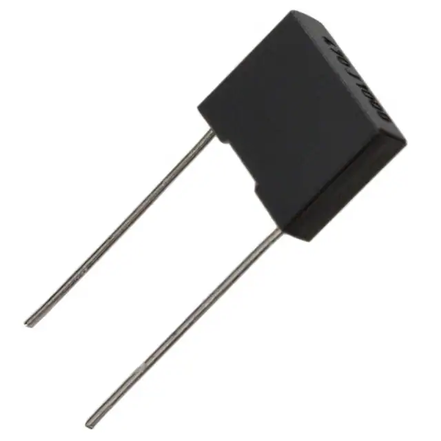
General Purpose Metallized Polyester Film Capacitors
R66, Radial, 7.5 mm Lead Spacing, 50 – 630 VDC
(Automotive Grade)
Overview
Applications
The R66 is constructed of metallized polyester film (wound
or stacked technology) with radial leads of tinned wire.
Radial leads are electrically welded to the contact metal
layer on the ends of the capacitor winding. The capacitor is
encapsulated with thermosetting resin in a box of material
meeting the UL 94 V–0 requirements.
Typical applications include blocking, coupling, decoupling,
bypassing, and interference suppression in low voltage
applications such as automotive. Not suitable for acrossthe-line application (see Suppressor Capacitors).
Automotive grade devices meet the demanding Automotive
Electronics Council's AEC–Q200 qualification requirements.
Benefits
• Voltage range: 50 – 630 VDC
• Capacitance range: 0.001 – 4.7 µF
• Lead Spacing: 7.5 mm
• Capacitance tolerance: ±5%, ±10%, ±20%
• Climatic category: 55/105/56
• Operating temperature range of −55°C to +105°C
• RoHS compliance and lead (Pb)-free terminations
• Tape & Reel packaging in accordance with IEC 60286–2
• Self-healing
• Automotive grade (AEC–Q200)
Part Number System
R66
Series
Metallized
Polyester
E
Rated Voltage
(VDC)
C = 50
D = 63
E = 100
I = 250
M = 400
P = 630
D
Length (mm)
D = 7.5
3100
Capacitance
Code (pF)
The last three
digits represent
significant figures.
First digit specifies
the number of zeros
to be added.
AA
7A
Packaging
Internal Use
See Ordering
Options Table
10
6A
7A
J
Capacitance
Tolerance
J = ±5%
K = ±10%
M = ±20%
Built Into Tomorrow
© KEMET Electronics Corporation • KEMET Tower • One East Broward Boulevard�
Fort Lauderdale, FL 33301 USA • 954-766-2800 • www.kemet.com
F3102_R66 • 9/13/2021
1
�General Purpose Metallized Polyester Film Capacitors
R66, Radial, 7.5 mm Lead Spacing, 50 – 630 VDC (Automotive Grade)
Ordering Options Table
Lead Spacing
Nominal
(mm)
Type of Leads and Packaging
LL Lead Length
(mm)
Lead and
Packaging
Code
4 +2/−0
H0=18.5 ±0.5
H0=18.5 ±0.5
AA
DQ
28
H0 = 18.5 ±0.5
2.7 +0.5/−0
3.5 +0.5/−0
10 ±1
3.2 +0.3/−0.2
17 +1/−2
CK
JA
JB
JC
JH
Z3
Standard Lead and Packaging Options
Bulk – Short Leads
Ammo Pack in Taping Style Figure 1
Ammo Pack in Taping Style Figure 2
Other Lead and Packaging Options
7.5
Tape & Reel (Standard Reel Ø 355 mm)
Bulk – Short Leads
Bulk – Short Leads
Bulk – Short Leads
Bulk – Short Leads
Bulk – Long Leads
Dimensions – Millimeters
FRONT VIEW
SIDE VIEW
L
T
H
S
LL
F
S
T
H
L
F
Nominal
Tolerance
Nominal
Tolerance
Nominal
Tolerance
Nominal
Tolerance
Nominal
Tolerance
7.5
7.5
7.5
7.5
±0.4
±0.4
±0.4
±0.4
3.0
4.0
5.0
6.0
+0.1/−0.5
+0.1/−0.5
+0.1/−0.5
+0.1/−0.5
8.0
9.0
10.5
12.0
+0.1/−0.5
+0.1/−0.5
+0.1/−0.5
+0.1/−0.5
10.0
10.0
10.0
10.5
+0.2/−0.5
+0.2/−0.5
+0.2/−0.5
+0.2/−0.5
0.5
0.6
0.6
0.6
±0.05
±0.05
±0.05
±0.05
Note: See Ordering Options Table for lead length (LL/H0) options.
© KEMET Electronics Corporation • KEMET Tower • One East Broward Boulevard�
Fort Lauderdale, FL 33301 USA • 954-766-2800 • www.kemet.com
F3102_R66 • 9/13/2021
2
�General Purpose Metallized Polyester Film Capacitors
R66, Radial, 7.5 mm Lead Spacing, 50 – 630 VDC (Automotive Grade)
Performance Characteristics
Dielectric
Plates
Winding
Leads
Protection
Related Documents
Polyester film (polyethylene terephthalate)
Metal layer deposited by evaporation under vacuum
Non-inductive type
Tinned wire
Plastic case, thermosetting resin filled. Box material is solvent resistant and flame retardant according to
UL94
IEC 60384–2
Rated Voltage VR (VDC)
50
63
100
250
400
630
Rated Voltage VR (VAC)
30
40
63
160
200
220
Capacitance Range (µF)
0.68 – 4.7
0.33 – 3.3
0.068 – 1.5
0.022 – 0.33
0.0068 – 0.15
0.001 – 0.047
Capacitance Values
E6 series (IEC 60063) measured at 1 kHz and +20 ±1°C
Capacitance Tolerance
±5%, ±10%, ±20%
Operating Temperature
Range
−55°C to +105°C Upper operating temperature of +125°C is allowed for a maximum operating time of
1,000 hours. (Stacked technology only)
Rated Temperature TR
Voltage Derating
Climatic Category
+85°C
Above +85°C DC and AC voltage derating is 1.25%/°C
55/105/56 IEC 60068–1
Storage time: ≤ 24 months from the date marked on the label package
Average relative humidity per year ≤ 70%
Storage Conditions
RH ≤ 85% for 30 days randomly distributed throughout the year
Dew is absent
Temperature: −40 to 80°C (see "Maximum Humidity in Storage Conditions" graph below)
Test Voltage
Capacitance Drift
1.6 x VR VDC for 2 seconds (between terminations) at +25°C ±5°C
Maximum 3% after a 2 year storage period at a temperature of +10°C to +40°C and a relative humidity of 40%
to 60%
Operational life > 200,000 hours
Reliability
(Reference IEC-61709)
Maximum Pulse Steepness
Temperature Coefficient
Self Inductance
(Lead Length ~ 2 mm)
Failure rate ≤ 1 FIT, T = +40°C, V = 0.5 x VR
Failure criteria: open or short circuit, capacitance change > 10%, DF 2 times the catalog limits,
IR < 0.005 x initial limit
dV/dt according to Table 1. For peak to peak voltages lower than rated voltage (Vpp 0.33 μF
50 VDC for VR ≤ 100 VDC
1 minute
100 VDC for VR > 100 VDC
1 minute
≥ 3,750 MΩ
(≥ 50,000 MΩ)*
≥ 1,250 MΩ • µF
(≥ 5,000 MΩ • µF )*
≥ 30,000 MΩ
(≥ 50,000 MΩ )*
* typical value
Maximum Humidity in Storage Condition
45
90
40
80
35
70
Maximum Overtemperature ∆Tlim vs Th
30
60
∆Tlim (°C)
50
40
30 Days
Annual Average
30
20
25
20
15
10
5
10
0
0
−40
−20
0
20
40
Temperature (°C)
60
80
0
5
10
15
20
25
30
35
40
45
50
55
60
65
70
75
80
85
90
95
100
105
110
115
Relative Humidity (%)
100
Temperature Th(°C)
Th is the maximum ambient temperature surrounding the capacitor or hottest contact point (e.g. tracks), whichever is higher, in the worst operation
conditions in °C.
Qualification
Automotive grade products meet or exceed the requirements outlined by the Automotive Electronics Council. Details
regarding test methods and conditions are referenced in document AEC–Q200, Stress Test Qualification for Passive
Components. For additional information regarding the Automotive Electronics Council and AEC–Q200, please visit their
website at www.aecouncil.com.
© KEMET Electronics Corporation • KEMET Tower • One East Broward Boulevard�
Fort Lauderdale, FL 33301 USA • 954-766-2800 • www.kemet.com
F3102_R66 • 9/13/2021
4
�General Purpose Metallized Polyester Film Capacitors
R66, Radial, 7.5 mm Lead Spacing, 50 – 630 VDC (Automotive Grade)
Maximum Voltage (Vrms) vs. Frequency (Sinusoidal Waveform/Th ≤ 40°C)
63 Vdc / 40 Vac
50 Vdc / 30 Vac
100
100
Voltage (Vrms)
1,000
Voltage (Vrms)
1,000
10
10
0.33
0.68
1.5
3.3
0.68 µF p = 7.5
1.5 µF p = 7.5
4.7 µF p = 7.5
1
0.1
1
Frequency (kHz)
10
1
100
0.1
µF
µF
µF
µF
p = 7.5
p = 7.5
p = 7.5
p = 7.5
1
100
1
0.1
µF
µF
µF
µF
Voltage (Vrms)
100
Voltage (Vrms)
1,000
0.1
0.22
0.47
1
p = 7.5
p = 7.5
p = 7.5
p = 7.5
1
Frequency (kHz)
10
0.033 µF
0.068 µF
0.15 µF
0.33 µF
10
1
100
0.1
1
0.1
Voltage (Vrms)
100
Voltage (Vrms)
100
1
p = 7.5
p = 7.5
p = 7.5
p = 7.5
1
Frequency (kHz)
Frequency (kHz)
10
100
630 Vdc / 220 Vac
1,000
0.01 µF
0.022 µF
0.047 µF
0.15 µF
100
p = 7.5
p = 7.5
p = 7.5
p = 7.5
400 Vdc / 200 Vac
1,000
10
10
250 Vdc / 160 Vac
100 Vdc / 63 Vac
1,000
10
Frequency (kHz)
10
100
© KEMET Electronics Corporation • KEMET Tower • One East Broward Boulevard�
Fort Lauderdale, FL 33301 USA • 954-766-2800 • www.kemet.com
0.001 µF
0.01 µF
0.022 µF
0.047 µF
10
1
0.1
1
p = 7.5
p = 7.5
p = 7.5
p = 7.5
Frequency (kHz)
10
F3102_R66 • 9/13/2021
100
5
�General Purpose Metallized Polyester Film Capacitors
R66, Radial, 7.5 mm Lead Spacing, 50 – 630 VDC (Automotive Grade)
Maximum Current (Irms) vs. Frequency (Sinusoidal Waveform/Th ≤ 40°C)
50 Vdc / 30 Vac
63 Vdc / 40 Vac
10
1
1
Current (A rms)
Current (A rms)
10
0.68 µF p = 7.5
1.5 µF p = 7.5
4.7 µF p = 7.5
0.1
0.01
0.1
1
Frequency (kHz)
0.1
0.33 µF
0.68 µF
1.5 µF
3.3 µF
10
100
0.01
0.1
1
Frequency (kHz)
p = 7.5
p = 7.5
p = 7.5
p = 7.5
10
100
250 Vdc / 160 Vac
100 Vdc / 63 Vac
10
1
1
Current (A rms)
Current (A rms)
10
0.1
0.01
0.1
0.1 µF p = 7.5
0.22 µF p = 7.5
0.47 µF p = 7.5
1 µF p = 7.5
0.1
1
Frequency (kHz)
100
10
0.01
0.033 µF
0.068 µF
0.15 µF
0.33 µF
0.1
1
400 Vdc / 200 Vac
10
100
10
100
630 Vdc / 220 Vac
1
1
0.001 µF
0.01 µF
0.022 µF
0.047 µF
Current (A rms)
10
Current (A rms)
10
0.1
p = 7.5
p = 7.5
p = 7.5
p = 7.5
0.1
0.01 µF
0.022 µF
0.047 µF
0.15 µF
0.01
Frequency (kHz)
p = 7.5
p = 7.5
p = 7.5
p = 7.5
0.1
1
Frequency (kHz)
10
p = 7.5
p = 7.5
p = 7.5
p = 7.5
100
© KEMET Electronics Corporation • KEMET Tower • One East Broward Boulevard�
Fort Lauderdale, FL 33301 USA • 954-766-2800 • www.kemet.com
0.01
0.1
1
Frequency (kHz)
F3102_R66 • 9/13/2021
6
�General Purpose Metallized Polyester Film Capacitors
R66, Radial, 7.5 mm Lead Spacing, 50 – 630 VDC (Automotive Grade)
Environmental Test Data
Damp Heat, Steady
State Test
Test Conditions:
Temperature:
Relative humidity (RH):
Test duration:
Endurance Test
+40°C ±2°C
93% ±2%
56 days
Test Conditions
Temperature:
Voltage applied:
Test duration:
Resistance to Soldering
Heat Test
+105°C ±2°C
1.25 x VC
2,000 hours
Test Conditions
Solder bath temperature:
Dipping time
(with heat screen):
260°C ±5°C
10 seconds ±1 second
Performances
|Δ C/C| ≤ 5%,
Δ tanδ ≤ 0.005 at 1 kHz
IR after test ≥ 50% of initial limit
Performances
|Δ C/C| ≤ 5%,
Δ tanδ ≤ 0.005 at 10 kHz for C ≤ 1µF
Δ tanδ ≤ 0.003 at 1 kHz for C > 1µF
IR after test ≥ 50% of initial limit
Performances
|Δ C/C| ≤ 2%,
Δ tanδ ≤ 0.005 at 10 kHz for C ≤ 1µF
Δ tanδ ≤ 0.003 at 1 kHz for C > 1µF
IR after test ≥ initial limit
Environmental Compliance
All KEMET MKT capacitors are RoHS compliant.
© KEMET Electronics Corporation • KEMET Tower • One East Broward Boulevard�
Fort Lauderdale, FL 33301 USA • 954-766-2800 • www.kemet.com
F3102_R66 • 9/13/2021
7
�General Purpose Metallized Polyester Film Capacitors
R66, Radial, 7.5 mm Lead Spacing, 50 – 630 VDC (Automotive Grade)
Table 1 – Ratings & Part Number Reference
Dimensions in mm
VDC
VAC
Capacitance
Value (µF)
B
H
50
50
50
50
50
63
63
63
63
63
63
63
100
100
100
100
100
100
100
100
100
250
250
250
250
250
250
250
250
400
400
400
400
400
400
400
400
400
630
630
630
630
630
630
630
630
630
630
630
30
30
30
30
30
40
40
40
40
40
40
40
63
63
63
63
63
63
63
63
63
160
160
160
160
160
160
160
160
200
200
200
200
200
200
200
200
200
220
220
220
220
220
220
220
220
220
220
220
0.68
1.0
1.5
2.2
4.7
0.33
0.47
0.68
1.0
1.5
2.2
3.3
0.068
0.10
0.15
0.22
0.33
0.47
0.68
1.0
1.5
0.022
0.033
0.047
0.068
0.10
0.15
0.22
0.33
0.0068
0.010
0.015
0.022
0.033
0.047
0.068
0.10
0.15
0.0010
0.0015
0.0022
0.0033
0.0047
0.0068
0.010
0.015
0.022
0.033
0.047
3.0
3.0
4.0
5.0
6.0
3.0
3.0
4.0
4.0
5.0
6.0
6.0
3.0
3.0
3.0
3.0
4.0
4.0
4.0
5.0
6.0
3.0
3.0
3.0
3.0
4.0
4.0
5.0
6.0
3.0
3.0
3.0
3.0
4.0
4.0
5.0
6.0
6.0
3.0
3.0
3.0
3.0
3.0
4.0
4.0
4.0
5.0
6.0
6.0
8.0
8.0
9.0
10.5
12.0
8.0
8.0
9.0
9.0
10.5
12.0
12.0
8.0
8.0
8.0
8.0
9.0
9.0
9.0
10.5
12.0
8.0
8.0
8.0
8.0
9.0
9.0
10.5
12.0
8.0
8.0
8.0
8.0
9.0
9.0
10.5
12.0
12.0
8.0
8.0
8.0
8.0
8.0
9.0
9.0
9.0
10.5
12.0
12.0
VDC
VAC
Capacitance
Value (µF)
B (mm)
H
(mm)
L
Lead
Spacing
dV/dt
(V/µs)
Maximum K0
(V2 /µs)
KEMET Internal
Part Number
Customer
Part Number
10.0
10.0
10.0
10.0
10.5
10.0
10.0
10.0
10.0
10.0
10.5
10.5
10.0
10.0
10.0
10.0
10.0
10.0
10.0
10.0
10.5
10.0
10.0
10.0
10.0
10.0
10.0
10.0
10.5
10.0
10.0
10.0
10.0
10.0
10.0
10.0
10.5
10.5
10.0
10.0
10.0
10.0
10.0
10.0
10.0
10.0
10.0
10.5
10.5
7.5
7.5
7.5
7.5
7.5
7.5
7.5
7.5
7.5
7.5
7.5
7.5
7.5
7.5
7.5
7.5
7.5
7.5
7.5
7.5
7.5
7.5
7.5
7.5
7.5
7.5
7.5
7.5
7.5
7.5
7.5
7.5
7.5
7.5
7.5
7.5
7.5
7.5
7.5
7.5
7.5
7.5
7.5
7.5
7.5
7.5
7.5
7.5
7.5
100
100
100
100
100
120
120
120
120
120
120
120
150
150
150
150
150
150
150
150
150
200
200
200
200
200
200
200
200
275
275
275
275
275
275
275
275
275
40
40
40
40
40
40
300
300
300
300
300
10000
10000
10000
10000
10000
15120
15120
15120
15120
15120
15120
15120
30000
30000
30000
30000
30000
30000
30000
30000
30000
100000
100000
100000
100000
100000
100000
100000
100000
220000
220000
220000
220000
220000
220000
220000
220000
220000
50400
50400
50400
50400
50400
50400
378000
378000
378000
378000
378000
66CD3680(1)6A(2)
66CD4100(1)6A(2)
66CD4150(1)6A(2)
66CD4220(1)6A(2)
66CD4470(1)6A(2)
66DD3330(1)7A(2)
66DD3470(1)6A(2)
66DD3680(1)7A(2)
66DD4100(1)7A(2)
66DD4150(1)7A(2)
66DD4220(1)6A(2)
66DD4330(1)6A(2)
66ED2680(1)7A(2)
66ED3100(1)7A(2)
66ED3150(1)7A(2)
66ED3220(1)7A(2)
66ED3330(1)7A(2)
66ED3470(1)7A(2)
66ED3680(1)7A(2)
66ED4100(1)7A(2)
66ED4150(1)6A(2)
66ID2220(1)7A(2)
66ID2330(1)7A(2)
66ID2470(1)7A(2)
66ID2680(1)6A(2)
66ID3100(1)7A(2)
66ID3150(1)7A(2)
66ID3220(1)7A(2)
66ID3330(1)6A(2)
66MD1680(1)7A(2)
66MD2100(1)7A(2)
66MD2150(1)7A(2)
66MD2220(1)6A(2)
66MD2330(1)7A(2)
66MD2470(1)7A(2)
66MD2680(1)7A(2)
66MD3100(1)6A(2)
66MD3150(1)6A(2)
66PD1100(1)10(2)
66PD1150(1)10(2)
66PD1220(1)10(2)
66PD1330(1)10(2)
66PD1470(1)10(2)
66PD1680(1)10(2)
66PD2100(1)7A(2)
66PD2150(1)7A(2)
66PD2220(1)7A(2)
66PD2330(1)6A(2)
66PD2470(1)6A(2)
R66CD3680(1)6A(2)
R66CD4100(1)6A(2)
R66CD4150(1)6A(2)
R66CD4220(1)6A(2)
R66CD4470(1)6A(2)
R66DD3330(1)7A(2)
R66DD3470(1)6A(2)
R66DD3680(1)7A(2)
R66DD4100(1)7A(2)
R66DD4150(1)7A(2)
R66DD4220(1)6A(2)
R66DD4330(1)6A(2)
R66ED2680(1)7A(2)
R66ED3100(1)7A(2)
R66ED3150(1)7A(2)
R66ED3220(1)7A(2)
R66ED3330(1)7A(2)
R66ED3470(1)7A(2)
R66ED3680(1)7A(2)
R66ED4100(1)7A(2)
R66ED4150(1)6A(2)
R66ID2220(1)7A(2)
R66ID2330(1)7A(2)
R66ID2470(1)7A(2)
R66ID2680(1)6A(2)
R66ID3100(1)7A(2)
R66ID3150(1)7A(2)
R66ID3220(1)7A(2)
R66ID3330(1)6A(2)
R66MD1680(1)7A(2)
R66MD2100(1)7A(2)
R66MD2150(1)7A(2)
R66MD2220(1)6A(2)
R66MD2330(1)7A(2)
R66MD2470(1)7A(2)
R66MD2680(1)7A(2)
R66MD3100(1)6A(2)
R66MD3150(1)6A(2)
R66PD1100(1)10(2)
R66PD1150(1)10(2)
R66PD1220(1)10(2)
R66PD1330(1)10(2)
R66PD1470(1)10(2)
R66PD1680(1)10(2)
R66PD2100(1)7A(2)
R66PD2150(1)7A(2)
R66PD2220(1)7A(2)
R66PD2330(1)6A(2)
R66PD2470(1)6A(2)
L (mm)
Lead
Spacing
dV/dt (V/
µs)
Max K0
(V2 /µs)
KEMET Internal
Part Number
Customer
Part Number
(1) Insert lead and packaging code. See Ordering Options Table for available options.
(2) J = 5%, K = 10%, M = 20%
Bold denotes wound capacitor technology
© KEMET Electronics Corporation • KEMET Tower • One East Broward Boulevard�
Fort Lauderdale, FL 33301 USA • 954-766-2800 • www.kemet.com
F3102_R66 • 9/13/2021
8
�General Purpose Metallized Polyester Film Capacitors
R66, Radial, 7.5 mm Lead Spacing, 50 – 630 VDC (Automotive Grade)
Soldering Process
The implementation of the RoHS directive has resulted in the selection of SnAgCu (SAC) alloys or SnCu alloys as primary solder.
This has increased the liquidus temperature from that of 183°C for SnPb eutectic alloy to 217 – 221°C for the new alloys. As a
result, the heat stress to the components, even in wave soldering, has increased considerably due to higher pre-heat and wave
temperatures. Polypropylene capacitors are especially sensitive to heat (the melting point of polypropylene is 160 – 170°C).
Wave soldering can be destructive, especially for mechanically small polypropylene capacitors (with lead spacing of 5 to 15
mm), and great care has to be taken during soldering. The recommended solder profiles from KEMET should be used. Please
consult KEMET with any questions. In general, the wave soldering curve from IEC Publication 61760–1 Edition 2, serves as a solid
guideline for successful soldering. Please see Figure 1.
Reflow soldering is not recommended for through-hole film capacitors. Exposing capacitors to a soldering profile in excess of the
above the recommended limits may result to degradation or permanent damage to the capacitors.
Do not place the polypropylene capacitor through an adhesive curing oven to cure resin for surface mount components. Insert
through-hole parts after the curing of surface mount parts. Consult KEMET to discuss the actual temperature profile in the oven,
if through-hole components must pass through the adhesive curing process. A maximum two soldering cycles is recommended.
Please allow time for the capacitor surface temperature to return to a normal temperature before the second soldering cycle.
Wave Soldering Recommendations
Manual Soldering Recommendations
300
Following is the recommendation for manual
soldering with a soldering iron.
2+3 seconds max
260°C
250
Second Wave
First Wave
Recommended Soldering Temperature
Temperature (°C)
200
400
Soldering Iron Bit Temperature (°C)
350
300
∆ T < 150°C
Cooling
Preheating
150
ca. 2°C/second
ca. 3.5°C/second typical
ca. 5°C/second
Tpreheat
100
Typical
250
50
200
150
0
100
0
40
80
120
160
200
240
Time (seconds)
50
0
0
1
2
3
4
5
6
7
8
Soldering Time (seconds)
The soldering iron tip temperature should
be set at 350°C (+10°C maximum) with the
soldering duration not to exceed more than 3
seconds.
© KEMET Electronics Corporation • KEMET Tower • One East Broward Boulevard�
Fort Lauderdale, FL 33301 USA • 954-766-2800 • www.kemet.com
F3102_R66 • 9/13/2021
9
�General Purpose Metallized Polyester Film Capacitors
R66, Radial, 7.5 mm Lead Spacing, 50 – 630 VDC (Automotive Grade)
Soldering Process cont.
Wave Soldering Recommendations cont.
1. The table indicates the maximum set-up temperature of the soldering process
Figure 1.
Dielectric
Film Material
Maximum
Preheat
Temperature
Maximum
Peak Soldering
Temperature
Capacitor Capacitor Capacitor Capacitor
Pitch
Pitch
Pitch
Pitch
≤ 15 mm > 15 mm ≤ 15 mm > 15 mm
Polyester
130°C
130°C
270°C
270°C
Polypropylene
110°C
130°C
260°C
270°C
Paper
130°C
140°C
270°C
270°C
Polyphenylene
Sulphide
150°C
160°C
270°C
270°C
2. The maximum temperature measured inside the capacitor:
Set the temperature so that inside the element the maximum temperature is below the limit:
Dielectric Film Material
Maximum temperature
measured inside the element
Polyester
160°C
Polypropylene
110°C
Paper
160°C
Polyphenylene Sulphide
160°C
Temperature monitored inside the capacitor.
Selective Soldering Recommendations
Selective dip soldering is a variation of reflow soldering. In this method, the printed circuit board with through-hole
components to be soldered is preheated and transported over the solder bath as in normal flow soldering without touching
the solder. When the board is over the bath, it is stopped and pre-designed solder pots are lifted from the bath with molten
solder only at the places of the selected components, and pressed against the lower surface of the board to solder the
components.
The temperature profile for selective soldering is similar to the double wave flow soldering outlined in this document,
however, instead of two baths, there is only one bath with a time from 3 to 10 seconds. In selective soldering, the risk of
overheating is greater than in double wave flow soldering, and great care must be taken so that the parts are not overheated.
© KEMET Electronics Corporation • KEMET Tower • One East Broward Boulevard�
Fort Lauderdale, FL 33301 USA • 954-766-2800 • www.kemet.com
F3102_R66 • 9/13/2021
10
�General Purpose Metallized Polyester Film Capacitors
R66, Radial, 7.5 mm Lead Spacing, 50 – 630 VDC (Automotive Grade)
Marking
FRONT
TOP
Capacitance
Capacitance
Tolerance
Rated
Voltage
Packaging Quantities
Lead Spacing
Thickness
(mm)
Height (mm)
Length (mm)
Bulk
Short Leads
7.5
3.0
4.0
5.0
6.0
8.0
9.0
10.5
12.0
10.0
10.0
10.0
10.5
1,500
2,000
1,500
1,000
© KEMET Electronics Corporation • KEMET Tower • One East Broward Boulevard�
Fort Lauderdale, FL 33301 USA • 954-766-2800 • www.kemet.com
Bulk
Standard Reel
Long Leads
355 mm
1,750
1,500
1,000
800
2,100
1,500
1,200
1,000
Ammo
Taped
2,800
2,100
1,600
1,350
F3102_R66 • 9/13/2021
11
�General Purpose Metallized Polyester Film Capacitors
R66, Radial, 7.5 mm Lead Spacing, 50 – 630 VDC (Automotive Grade)
Lead Taping & Packaging (IEC 60286–2)
Figure 1 — Lead Spacing 5 & 7.5 mm
P1
P
P2
Figure 2 — Lead Spacing 7.5 mm
P
P1
∆h
A
H0
W0
P0
F
t
A
H0
Ød
W1
∆h
W2
B
Ød
W0
W1
W
W
P0
F
D0
∆h
∆h
W2
B
P
t
t
A−B
t
A−B
D0
Dimensions (mm)
Description
Symbol
5
Figure 1
Lead Spacing
7.5
7.5
Figure 1
Figure 2
Tolerance
Lead wire diameter
d
0.5 – 0.6
0.5 – 0.6
0.5 – 0.6
±0.05
Taping lead space
P
12.7
12.7
12.7
±1
Feed hole lead space
P0
12.7
12.7
12.7
±0.2*
Centering of the lead wire
P1
3.85
2.6
3.75
±0.7
Centering of the body
P2
6.35
6.35
Lead spacing
F
5
7.5
7.5
+0.6/−0.1
∆h
0
0
0
±2
H0 **
18.5
18.5
18.5
±0.5
Component alignment
Height of component from tape
center
±1.3
Carrier tape width
W
18
18
18
+1/−0.5
Hold down tape width
W0
6
6
6
Minimum
Hole position
W1
9
9
9
±0.5
Hold down tape position
W2
3
3
3
Maximum
Feed hole diameter
D0
4
4
4
±0.2
Tape thickness
t
0.7
0.7
0.7
±0.2
*Maximum 1 mm on 20 lead spaces.
**H0 = 16.5 mm is available upon request.
For orders of capacitors with lead space = 7.5 mm, please specify the
requested version: Figure 1 = Packaging code “CK” / Figure 2 – Packaging code “28”
© KEMET Electronics Corporation • KEMET Tower • One East Broward Boulevard�
Fort Lauderdale, FL 33301 USA • 954-766-2800 • www.kemet.com
F3102_R66 • 9/13/2021
12
�General Purpose Metallized Polyester Film Capacitors
R66, Radial, 7.5 mm Lead Spacing, 50 – 630 VDC (Automotive Grade)
Ammo Specifications
Reel Specifications
Dimensions in mm
Dimensions in mm
H
W
T
D
H
W
360 *
340
59
355
30
55 maximum
* Lower dimension available upon request (maximum 295 mm)
D
H
H
W
T
W
© KEMET Electronics Corporation • KEMET Tower • One East Broward Boulevard�
Fort Lauderdale, FL 33301 USA • 954-766-2800 • www.kemet.com
F3102_R66 • 9/13/2021
13
�General Purpose Metallized Polyester Film Capacitors
R66, Radial, 7.5 mm Lead Spacing, 50 – 630 VDC (Automotive Grade)
KEMET Electronics Corporation Sales Offices
For a complete list of our global sales offi ces, please visit www.kemet.com/sales.
Disclaimer
All product specifi cations, statements, information and data (collectively, the “Information”) in this datasheet are subject to change. The customer is responsible for
checking and verifying the extent to which the Information contained in this publication is applicable to an order at the time the order is placed. All Information given
herein is believed to be accurate and reliable, but it is presented without guarantee, warranty, or responsibility of any kind, expressed or implied.
Statements of suitability for certain applications are based on KEMET Electronics Corporation’s (“KEMET”) knowledge of typical operating conditions for such
applications, but are not intended to constitute – and KEMET specifi cally disclaims – any warranty concerning suitability for a specifi c customer application or use.
The Information is intended for use only by customers who have the requisite experience and capability to determine the correct products for their application. Any
technical advice inferred from this Information or otherwise provided by KEMET with reference to the use of KEMET’s products is given gratis, and KEMET assumes
no obligation or liability for the advice given or results obtained.
Although KEMET designs and manufactures its products to the most stringent quality and safety standards, given the current state of the art, isolated component
failures may still occur. Accordingly, customer applications which require a high degree of reliability or safety should employ suitable designs or other safeguards
(such as installation of protective circuitry or redundancies) in order to ensure that the failure of an electrical component does not result in a risk of personal injury
or property damage.
Although all product–related warnings, cautions and notes must be observed, the customer should not assume that all safety measures are indicted or that other
measures may not be required.
KEMET is a registered trademark of KEMET Electronics Corporation.
© KEMET Electronics Corporation • KEMET Tower • One East Broward Boulevard�
Fort Lauderdale, FL 33301 USA • 954-766-2800 • www.kemet.com
F3102_R66 • 9/13/2021
14
�