General Purpose Metallized Polyester Film Capacitors
R82 Series, Radial, 5 mm Lead Spacing, 50 – 400 VDC
(Automotive Grade)
Overview
Applications
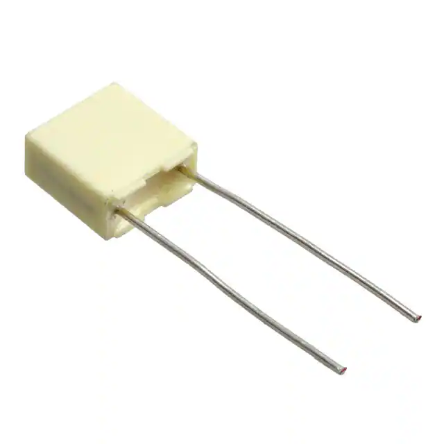
The R82 Series is constructed of metallized polyester film
(wound or stacked technology) with radial leads of tinned
wire. Radial leads are electrically welded to the contact
metal layer on the ends of the capacitor winding. The
capacitor is encapsulated with thermosetting resin in a box
of material meeting the UL 94V–0 requirements.
Typical applications include blocking, coupling, decoupling,
timing and oscillator circuits. Not suitable for across-theline application (see Suppressor Capacitors).
Automotive grade devices meet the demanding Automotive
Electronics Council's AEC–Q200 qualification requirements.
Benefits
• Voltage range: 50 – 400 VDC
• Capacitance range: 0.001 µF – 4.7 µF
• Lead Spacing: 5 mm
• Capacitance tolerance: ±5%, ±10%, ±20%
• Climatic category: 55/105/56
• Operating temperature range of -55˚C to +105˚C
• RoHS compliance and lead-free terminations
• Tape and reel packaging in accordance with IEC 60286–2
• Self-healing
• Automotive grade (AEC–Q200)
Click image above for interactive 3D content
Open PDF in Adobe Reader for full functionality
Part Number System
R82
Series
Metallized
Polyester
D
Rated Voltage
(VDC)
C = 50
D = 63
E = 100
I = 250
M = 400
C
Length (mm)
C = 5.0
3470
Capacitance
Code (pF)
The last three
digits represent
significant figures.
First digit specifies
the number of zeros
to be added.
AA
60
J
Packaging
Internal Use
See Ordering
Options Table
30
50
60
70
Capacitance
Tolerance
J = ±5%
K = ±10%
M = ±20%
One world. One KEMET
© KEMET Electronics Corporation • P.O. Box 5928 • Greenville, SC 29606 (864) 963-6300 • www.kemet.com
F3101_R82 • 5/4/2017
1
�Film Through-Hole Capacitors – General Purpose Metallized Polyester Film Capacitors
R82 Series, Radial, 5 mm Lead Spacing, 50 – 400 VDC (Automotive Grade)
Ordering Options Table
Lead Spacing
Nominal
(mm)
Type of Leads and Packaging
LL Lead Length
(mm)
Lead and
Packaging
Code
4 +1.5/-0
H0=18.5 +/- 0.5
AA
DQ
H0 = 18.5 +/- 0.5
2.7 +0.5/-0
3.5 +0.5/-0
10 +/- 1
4.0 +0.5/-0
3.2 +0.3/-0.2
17 +1/-2
CK
JA
JB
JC
JE
JH
Z3
Standard Lead and Packaging Options
Bulk (Bag)–Short Leads
Ammo Pack
Other Lead and Packaging Options
Tape & Reel (Standard Reel)
Bulk (Bag)–Short Leads
Bulk (Bag)–Short Leads
Bulk (Bag)–Short Leads
Bulk (Bag)–Short Leads
Bulk (Bag)–Short Leads
Bulk (Bag)–Long Leads
5
Dimensions – Millimeters
FRONT VIEW
SIDE VIEW
L
B
H
d
0.5
LL
p
p
B
H
L
d
Nominal
Tolerance
Nominal
Tolerance
Nominal
Tolerance
Nominal
Tolerance
Nominal
Tolerance
5.0
5.0
5.0
5.0
5.0
5.0
+/-0.4
+/-0.4
+/-0.4
+/-0.4
+/-0.4
+/-0.4
2.5
3.5
4.5
5.0
6.0
7.2
+0.1
+0.1
+0.1
+0.1
+0.1
+0.1
6.5
7.5
9.5
10.0
11.0
13.0
+0.1
+0.1
+0.1
+0.1
+0.1
+0.1
7.2
7.2
7.2
7.2
7.2
7.2
+0.2
+0.2
+0.3
+0.3
+0.3
+0.3
0.5
0.5
0.5
0.5
0.5
0.6
+/-0.05
+/-0.05
+/-0.05
+/-0.05
+/-0.05
+/-0.05
Note: See Ordering Options Table for lead length (LL/H 0) options.
© KEMET Electronics Corporation • P.O. Box 5928 • Greenville, SC 29606 (864) 963-6300 • www.kemet.com
F3101_R82 • 5/4/2017
2
�Film Through-Hole Capacitors – General Purpose Metallized Polyester Film Capacitors
R82 Series, Radial, 5 mm Lead Spacing, 50 – 400 VDC (Automotive Grade)
Performance Characteristics
Dielectric
Plates
Winding
Leads
Protection
Related Documents
Polyester film (polyethylene terephthalate).
Metal layer deposited by evaporation under vacum.
Non-inductive type.
Tinned wire.
Plastic case, thermosetting resin filled. Box material is solvent resistant and flame retardant according to
UL94.
IEC 60384-2
Rated Voltage VR (VDC)
50
63
100
Rated Voltage VR (VAC)
30
40
63
140
160
160
200
0.001 – 1
0.022 –
0.22
0.0068 –
0.15
0.0068 –
0.068
0.001 –
0.047
Capacitance Range (µF)
Capacitance Values
2.2 – 4.7
±5%, ±10%, ±20%
Operating Temperature
Range
-55°C to 105°C
Voltage Derating
Climatic Category
250
400
400
E6 series (IEC 60063) measured @ 1 kHz and +20 ±1°C
Capacitance Tolerance
Rated Temperature TR
0.1 – 1.5
250
+85°C
Above +85°C DC and AC voltage derating is 1.25%/°C
55/105/56 IEC 60068-1
Storage time: ≤ 24 months from the date marked on the label package
Average relative humidity per year ≤ 70%
Storage Conditions
RH ≤ 85% for 30 days randomly distributed throughout the year
Dew is absent
Temperature: -40 to 80°C (see "Maximum Humidity in Storage Conditions" graph below)
Test Voltage
Capacitance Drift
1.4 x VR VDC for 2 seconds (between terminations) @ +25°C ±5°C
Maximum 3% after a 2 year storage period at a temperature of +10°C to +40°C and a relative humidity of 40%
to 60%
Operational life >200,000 hours
Reliability
(Reference MIL-HDBK-217)
Failure rate ≤ 1 FIT, T = +40°C, V = 0.5 x VR
Failure criteria: open or short circuit, cap. change > 10%, DF 2 times the catalog limits, IR < 0.005 x initial limit
Maximum Pulse Steepness
Temperature Coefficient
Self Inductance
(Lead Length ~ 2 mm)
dV/dt according to Table 1. For peak to peak voltages lower than rated voltage (Vpp 15 mm
Polyester
130°C
130°C
130°C
270°C
270°C
Polypropylene
100°C
110°C
130°C
260°C
270°C
Paper
130°C
130°C
140°C
270°C
270°C
Polyphenylene
Sulphide
150°C
150°C
160°C
270°C
270°C
2. The maximum temperature measured inside the capacitor:
Set the temperature so that inside the element the maximum temperature is below the limit:
Dielectric Film Material
Maximum temperature
measured inside the element
Polyester
160°C
Polypropylene
110°C
Paper
160°C
Polyphenylene
sulphide
160°C
Temperature monitored inside the capacitor.
Selective Soldering Recommendations
Selective dip soldering is a variation of reflow soldering. In this method, the printed circuit board with through-hole
components to be soldered is preheated and transported over the solder bath as in normal flow soldering without touching
the solder. When the board is over the bath, it is stopped and pre-designed solder pots are lifted from the bath with molten
solder only at the places of the selected components, and pressed against the lower surface of the board to solder the
components.
The temperature profile for selective soldering is similar to the double wave flow soldering outlined in this document,
however, instead of two baths, there is only one bath with a time from 3 to 10 seconds. In selective soldering, the risk of
overheating is greater than in double wave flow soldering, and great care must be taken so that the parts are not overheated.
© KEMET Electronics Corporation • P.O. Box 5928 • Greenville, SC 29606 (864) 963-6300 • www.kemet.com
F3101_R82 • 5/4/2017
10
�Single-sided
Single-sided
Metallized
Film Through-Hole Capacitors –Metallized
General Purpose Metallized Polyester Film Capacitors
Polypropylene
Polypropylene
R82 Series, Radial, 5 mm Lead Spacing,
Film 50 – 400 VDC (Automotive Grade)
Film
Double-sided
Metallized
Polyester
Carrier
Film
Polyprop
Film Die
Construction
3 Sections
Wound
3 Sections
4 Sections
Single-sided Metallized
Polypropylene Film
(First Layer)
Molded Plastic
Case
Single-sided Metallized
Polypropylene Film
(Second Layer)
Metallized Impregnated Paper
Detailed Cross Section
Molded Plastic
Case
Self-Extinguishing
Resin
Metallized Polyphenylene
Sulfide Film (SMR)
Polyp
Margin
Margin
Metal Contact
Layer
Metal Contact
Metallized
Impregnated
Paper
MetallizedLayer
Polyphenylene Sulfide Film with
Vacuum-Evaporated
Aluminum Electrodes
Metal Foil
Poly
Film
Margin
1 Section
1 Section
1 Section
Leads
Single-sided
WindingMetallized
SchemePolyester Film
AXIAL - Polyprop
Single-sided
Metallized
Polyester
Film
Polypropylene
Film Dielectric
Metal Foil
1 Section
1 Section
AXIAL - Single-sided Metallized
Polypropylene Film
AXIAL - Single-sided Metallized
Polyester Film
Single-sided
Metallized
Polypropylene
Film
1 Section
© KEMET Electronics Corporation • P.O. Box 5928 • Greenville, SC 29606 (864) 963-6300 • www.kemet.com
Doub
Me
Polyes
Single-sided
Metallized
Polyester
Film
1 Section
F3101_R82 • 5/4/2017
11
�Film Through-Hole Capacitors – General Purpose Metallized Polyester Film Capacitors
R82 Series, Radial, 5 mm Lead Spacing, 50 – 400 VDC (Automotive Grade)
Construction cont'd
Stacked
Molded Plastic
Case
Detailed Cross Section
Molded Plastic
Case
Single-sided Metallized
Polyester Film
(First Layer) Self-Extinguishing
Resin
Single-sided Metallized
Polyester Film
(Second Layer)
Margin
Metal Contact
Layer
Metal Contact
Layer
Leads
© KEMET Electronics Corporation • P.O. Box 5928 • Greenville, SC 29606 (864) 963-6300 • www.kemet.com
F3101_R82 • 5/4/2017
12
�Film Through-Hole Capacitors – General Purpose Metallized Polyester Film Capacitors
R82 Series, Radial, 5 mm Lead Spacing, 50 – 400 VDC (Automotive Grade)
Marking
Wound
Stacked
FRONT
Capacitance
Tolerance
Capacitance
Voltage
FRONT
Capacitance
Tolerance
Capacitance
Voltage
Packaging Quantities
Lead Spacing
Thickness
(mm)
Height (mm)
Length (mm)
Bulk
Short Leads
5
2.5
3.5
4.5
5.0
6.0
7.2
6.5
7.5
9.5
10.0
11.0
13.0
7.2
7.2
7.2
7.2
7.2
7.2
3,000
2,000
1,500
1,000
2,000
1,500
Bulk
Standard Reel
Long Leads
355 mm
4,000
3,000
2,000
1,500
1,000
750
© KEMET Electronics Corporation • P.O. Box 5928 • Greenville, SC 29606 (864) 963-6300 • www.kemet.com
2,500
1,800
1,400
1,200
1,000
800
Ammo
Taped
3,500
2,500
1,900
1,700
1,400
1,150
F3101_R82 • 5/4/2017
13
�Film Through-Hole Capacitors – General Purpose Metallized Polyester Film Capacitors
R82 Series, Radial, 5 mm Lead Spacing, 50 – 400 VDC (Automotive Grade)
Lead Taping & Packaging (IEC 60286–2)
Figure 2 – Lead Space 7.5 mm
Figure 1 – Lead Space 5 & 7.5 mm
Dimensions (mm)
Description
Symbol
5
Figure 1
Lead Spacing
7.5
7.5
Figure 1
Figure 2
Tolerance
Lead wire diameter
d
0.5–0.6
0.5–0.6
0.5–0.6
±0.05
Taping lead space
P
12.7
12.7
12.7
±1
Feed hole lead space
P0
12.7
12.7
12.7
±0.2*
Centering of the lead wire
P1
3.85
2.6
3.75
±0.7
Centering of the body
P2
6.35
6.35
Lead spacing
F
5
7.5
7.5
+0.6 -0.1
∆h
0
0
0
±2
H0 **
18.5
18.5
18.5
±0.5
Carrier tape width
W
18
18
18
+1 -0.5
Hold down tape width
W0
6
6
6
minimum
Hole position
W1
9
9
9
±0.5
Hold down tape position
W2
3
3
3
maximum
Feed hole diameter
D0
4
4
4
±0.2
Tape thickness
t
0.7
0.7
0.7
±0.2
Component alignment
Height of component from tape
center
±1.3
*Maximum 1 mm on 20 lead spaces.
**H0 = 16.5 mm is available upon request.
For orders of capacitors with lead space = 7.5 mm, please specify the
requested version (Figure 1 or Figure 2).
© KEMET Electronics Corporation • P.O. Box 5928 • Greenville, SC 29606 (864) 963-6300 • www.kemet.com
F3101_R82 • 5/4/2017
14
�Film Through-Hole Capacitors – General Purpose Metallized Polyester Film Capacitors
R82 Series, Radial, 5 mm Lead Spacing, 50 – 400 VDC (Automotive Grade)
Ammo Specifications
Reel Specifications
Dimensions in mm
Dimensions in mm
H
W
T
D
H
W
360 *
340
59
355
30
55 maximum
* Lower dimension available upon request (maximum 295 mm)
© KEMET Electronics Corporation • P.O. Box 5928 • Greenville, SC 29606 (864) 963-6300 • www.kemet.com
F3101_R82 • 5/4/2017
15
�Film Through-Hole Capacitors – General Purpose Metallized Polyester Film Capacitors
R82 Series, Radial, 5 mm Lead Spacing, 50 – 400 VDC (Automotive Grade)
KEMET Electronics Corporation Sales Offices
For a complete list of our global sales offi ces, please visit www.kemet.com/sales.
Disclaimer
All product specifi cations, statements, information and data (collectively, the “Information”) in this datasheet are subject to change. The customer is responsible for
checking and verifying the extent to which the Information contained in this publication is applicable to an order at the time the order is placed.
All Information given herein is believed to be accurate and reliable, but it is presented without guarantee, warranty, or responsibility of any kind, expressed or implied.
Statements of suitability for certain applications are based on KEMET Electronics Corporation’s (“KEMET”) knowledge of typical operating conditions for such
applications, but are not intended to constitute – and KEMET specifi cally disclaims – any warranty concerning suitability for a specifi c customer application or use.
The Information is intended for use only by customers who have the requisite experience and capability to determine the correct products for their application. Any
technical advice inferred from this Information or otherwise provided by KEMET with reference to the use of KEMET’s products is given gratis, and KEMET assumes no
obligation or liability for the advice given or results obtained.
Although KEMET designs and manufactures its products to the most stringent quality and safety standards, given the current state of the art, isolated component
failures may still occur. Accordingly, customer applications which require a high degree of reliability or safety should employ suitable designs or other safeguards
(such as installation of protective circuitry or redundancies) in order to ensure that the failure of an electrical component does not result in a risk of personal injury or
property damage.
Although all product–related warnings, cautions and notes must be observed, the customer should not assume that all safety measures are indicted or that other
measures may not be required.
KEMET is a registered trademark of KEMET Electronics Corporation.
© KEMET Electronics Corporation • P.O. Box 5928 • Greenville, SC 29606 (864) 963-6300 • www.kemet.com
F3101_R82 • 5/4/2017
16
�


 工商网监
湘ICP备2023018690号
工商网监
湘ICP备2023018690号
