Surface Mount Multilayer Ceramic Chip Capacitors (SMD MLCCs)
KPS HV, Large Case, SM Series, X7R Dielectric,
500 – 10,000 VDC (Industrial Grade)
Overview
KPS HV (KEMET Power Solutions, High Voltage), Large
Case (≥ 1515), SM Series capacitors in X7R dielectric are
designed to meet robust performance standards required
in higher reliability industrial applications. Utilizing leadframe technology, SM Series devices isolate the multilayer
ceramic chip component from the printed circuit board
providing advanced mechanical and thermal stress performance. Isolation of the chip component also addresses
concerns for audible, microphonic noise that may occur
when a bias voltage is applied. Although this technology
does not eliminate the potential for mechanical damage
that may propagate during extreme environmental and handling conditions, it does demonstrate superior performance
over non-isolating systems. Available in both formed "L"
and "J" lead configurations, SM Series devices offer up to
10 mm of board flex capability and exhibit lower ESR, ESL and
higher current discharge capability when compared to other
dielectric solutions.
Combined with the stability of an X7R dielectric, KEMET’s
High Voltage SM Series devices exhibit a predictable change
in capacitance with respect to time and voltage and boast
a minimal change in capacitance with reference to ambient
temperature. Capacitance change is limited to ±15% from
−55°C to +125°C.
KEMET's Industrial grade products offer additional screening
options for higher reliability applications. Both Group A and
Group B testing/inspection options per MIL–PRF–49467 are
available for the SM Series.
Benefits
• −55°C to +125°C operating temperature range
• Large Case Sizes (≥ 1515)
• Formed “L” or “J” leadframe configurations
• Group A and B screening per MIL–PRF–49467 available
• Reliable and robust leadframe termination system
• DC voltage ratings of 500 V, 1 KV, 2 KV, 3 KV, 4 KV, 5 KV,
7.5 KV, and 10 KV
• Capacitance offerings ranging from 150 pF up to 5.6 μF
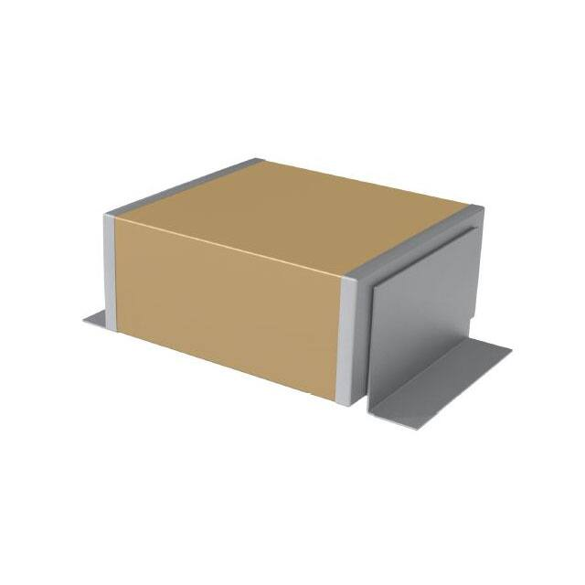
Click image above for interactive 3D content
Ordering Information
Open PDF in Adobe Reader for full functionality
SM20
B
153
K
501
B
M
Style/Size
Dielectric
Capacitance
Code (pF)
Capacitance
Tolerance
Rated Voltage
(VDC)
Lead
Configuration1
Testing/
Inspection Option2
Two significant
digits and
number of zeros
K = ±10%
M = ±20%
501 = 500
102 = 1,000
202 = 2,000
302 = 3,000
402 = 4,000
502 = 5,000
752 = 7,500
103 = 10,000
A = Formed "L"
B = Formed "J"
Blank = None
M = Group A per MIL–PRF–49467
SM20
SM21
SM22
SM23
SM24
SM25
SM26
SM30
SM31
SM33
SM34
SM35
SM36
B = X7R
Standard lead configuration is formed "J". If the appropriate character is excluded from the ordering code, the assumed lead configuration will be
formed "J".
2
Group B testing/inspection option per MIL–PRF–49467 is available upon request. Please contact KEMET for ordering details.
1
One world. One KEMET
© KEMET Electronics Corporation • P.O. Box 5928 • Greenville, SC 29606 • 864-963-6300 • www.kemet.com
C1033_X7R_KPS_HIVOLT_SMD • 8/18/2016
1
�Surface Mount Multilayer Ceramic Chip Capacitors (SMD MLCCs)
KPS HV, Large Case, SM Series, X7R Dielectric, 500 – 10,000 VDC (Industrial Grade)
Dimensions – Inches (Millimeters)
FORMED LEAD (L)
FORMED LEAD (J)
Top View
Top View
Profile View
(L)
(L)
A W
LL
Profile View
(J)
T
0.030±0.010
(0.76±0.25)
L
Style/
Size
L
Length
W
Width
SM20
SM21
SM22
SM23
SM24
SM25
SM26
SM30
SM31
0.150±0.015 (3.81±0.38)
0.200±0.020 (5.08±0.51)
0.250±0.020 (6.35±0.51)
0.350±0.030 (8.89±0.76)
0.450±0.030 (11.43±0.76)
0.550±0.030 (14.00±0.76)
0.650±0.030 (16.50±0.76)
0.300±0.030 (7.62±0.76)
0.400±0.030 (10.20±0.76)
0.150±0.015 (3.81±0.38)
0.200±0.020 (5.08±0.51)
0.200±0.020 (5.08±0.51)
0.300±0.030 (7.62±0.76)
0.400±0.030 (10.20±0.76)
0.500±0.030 (12.70±0.76)
0.600±0.030 (15.20±0.76)
0.150±0.015 (3.81±0.38)
0.200±0.020 (5.08±0.51)
SM33
0.700±0.030 (17.08±0.76)
SM34
SM35
SM36
0.900±0.030 (22.90±0.76)
1.100±0.030 (27.90±0.76)
1.350±0.030 (33.00±0.76)
T
Thickness
Max.
(J)
A W
LL
L
A
Lead Width
Max.
LL
Lead Length
(Formed "L")
0.130 (3.30)
0.180 (4.57)
0.220 (5.59)
0.140 (3.55)
0.130 (3.30)
0.100 (2.54)
0.300±0.030 (7.62±0.76)
0.180 (4.57)
0.200 (5.08)
0.400±0.030 (10.20±0.76)
0.500±0.030 (12.70±0.76)
0.600±0.030 (15.20±0.76)
0.220 (5.59)
0.300 (7.62)
0.400 (10.2)
0.500 (12.7)
0.030±0.010
(0.76±0.25)
LL
Lead Length
(Formed "J")
0.040±0.010
(1.02±0.25)
0.100 (2.54)
0.200 (5.08)
0.300 (7.62)
0.400 (10.20)
0.500 (12.70)
T
0.100±0.020
(2.54±0.51)
0.100±0.020
(2.54±0.51)
Benefits cont'd
• Advanced protection against thermal and mechanical
stress
• Provides up to 10 mm of board flex capability
• Reduces audible, microphonic noise
• Low ESR and ESL
• Non-polar device, minimizing installation concerns
• Silver plated copper alloy leadframe termination system
Applications
Typical applications include switch mode power supplies (input filters, resonators, tank circuits, snubber circuits, output
filters), high voltage coupling and DC blocking, voltage multiplier circuits, DC/DC converters and coupling capacitors in Ćuk
converters, noise reduction (piezoelectric/mechanical), circuits with a direct battery or power source connection, critical
and safety relevant circuits without (integrated) current limitation and any application that is subject to high levels of board
flexure or temperature cycling. Markets include power supply, LCD fluorescent backlight ballasts, HID lighting, telecom
equipment, industrial and medical equipment/control and Military.
© KEMET Electronics Corporation • P.O. Box 5928 • Greenville, SC 29606 • 864-963-6300 • www.kemet.com
C1033_X7R_KPS_HIVOLT_SMD • 8/18/2016
2
�Surface Mount Multilayer Ceramic Chip Capacitors (SMD MLCCs)
KPS HV, Large Case, SM Series, X7R Dielectric, 500 – 10,000 VDC (Industrial Grade)
Qualification/Certification
Industrial Grade products are subject to internal qualification. Details regarding test methods and conditions are referenced
in Table 3, Performance & Reliability.
Environmental Compliance
RoHS Compliant with Exemption(s).
Electrical Parameters/Characteristics
Item
Parameters/Characteristics
Operating Temperature Range
−55°C to +125°C
Capacitance Change with Reference to
+25°C and 0 VDC Applied (TCC)
±15%
Aging Rate (Maximum % Capacitance Loss/Decade Hour)
3.0%
Dielectric Withstanding Voltage (DWV)
Dissipation Factor (DF) Maximum Limit at 25ºC
Insulation Resistance (IR) Limit at 25°C
150% of rated voltage for voltage rating of ≤ 1,250 VDC
120% of rated voltage for voltage rating of > 1,250 VDC
(5±1 seconds and charge/discharge not exceeding 50 mA)
2.5%
1,000 megohm microfarads or 100 GΩ
(Rated voltage DC applied for 120±5 seconds at 25°C for voltage rating of ≤ 500 VDC)
(500 VDC applied for 120±5 seconds at 25°C for voltage rating of > 500 VDC)
Regarding aging rate: Capacitance measurements (including tolerance) are indexed to a referee time of 1,000 hours.
To obtain IR limit, divide MΩ-µF value by the capacitance and compare to GΩ limit. Select the lower of the two limits.
Capacitance and dissipation factor (DF) measured under the following conditions:
1 kHz ±50 Hz and 1.0 Vrms ±0.2 V if capacitance > 100 pF
Note: When measuring capacitance it is important to ensure the set voltage level is held constant. The HP4284 and Agilent E4980 have a feature known
as Automatic Level Control (ALC). The ALC feature should be switched to "ON."
Post Environmental Limits
High Temperature Life, Biased Humidity, Moisture Resistance
Dielectric
Rated DC Voltage
Capacitance Value
Dissipation Factor
(Maximum %)
Capacitance
Shift
X7R
All
All
3.0
±20%
© KEMET Electronics Corporation • P.O. Box 5928 • Greenville, SC 29606 • 864-963-6300 • www.kemet.com
C1033_X7R_KPS_HIVOLT_SMD • 8/18/2016
3
�Surface Mount Multilayer Ceramic Chip Capacitors (SMD MLCCs)
KPS HV, Large Case, SM Series, X7R Dielectric, 500 – 10,000 VDC (Industrial Grade)
Table 1A – Capacitance Range/Selection Waterfall SM20 – SM24 Style/Size
Style/Size
SM20
SM21
0.150 ± 0.015
(3.81 ± 0.38)
0.150 ± 0.015
(3.81 ± 0.38)
0.130
(3.30)
0.100
(2.54)
0.100 ± 0.020
(2.54 ± 0.51)
0.040 ± 0.010
(1.02 ± 0.25)
0.200 ± 0.020
(5.08 ± 0.51)
0.200 ± 0.020
(5.08 ± 0.51)
0.180
(4.57)
0.100
(2.54)
0.100 ± 0.020
(2.54 ± 0.51)
0.040 ± 0.010
(1.02 ± 0.25)
SM22
SM23
SM24
0.350 ± 0.030
(8.89 ± 0.76)
0.300 ± 0.030
(7.62 ± 0.76)
0.220
(5.59)
0.200
(5.08)
0.100 ± 0.020
(2.54 ± 0.51)
0.100 ± 0.020
(2.54 ± 0.51)
0.450 ± 0.030
(11.43 ± 0.76)
0.400 ± 0.030
(10.20 ± 0.76)
0.220
(5.59)
0.300
(7.62)
0.100 ± 0.020
(2.54 ± 0.51)
0.100 ± 0.020
(2.54 ± 0.51)
Dimensions – inches (mm)
Length
Width
Thickness
Maximum
Lead Width
Maximum
Lead Length
"L"
Lead Length
"J"
0.250 ± 0.020
(6.35 ± 0.51)
0.200 ± 0.020
(5.08 ± 0.51)
0.180
(4.57)
0.100
(2.54)
0.100 ± 0.020
(2.54 ± 0.51)
0.040 ± 0.010
(1.02 ± 0.25)
X7R Dielectric
Voltage Code
Voltage DC
501 102 202 501 102 202 302 501 102 202 302 501 102 202 302 402 501 102 202 302 402 502
500 1 K
2 K 500 1 K
331
391
471
561
681
821
102
122
152
182
222
272
332
392
472
562
682
822
103
123
153
183
223
273
333
393
473
563
683
823
331
391
471
561
681
821
102
122
152
182
222
272
332
392
2K
3 K 500 1 K
Capacitance
330 pF
390 pF
470 pF
560 pF
680 pF
820 pF
1,000 pF
1,200 pF
1,500 pF
1,800 pF
2,200 pF
2,700 pF
3,300 pF
3,900 pF
4,700 pF
5,600 pF
6,800 pF
8,200 pF
0.01 µF
0.012 µF
0.015 µF
0.018 µF
0.022 µF
0.027 µF
0.033 µF
0.039 µF
0.047 µF
0.056 µF
0.068 µF
0.082 µF
0.1 µF
0.12 µF
0.15 µF
0.18 µF
0.22 µF
0.27 µF
0.33 µF
0.39 µF
0.47 µF
0.56 µF
0.68 µF
0.82 µF
1.0 µF
1.2 µF
2K
3 K 500 1 K
2K
3K
4 K 500 1 K
2K
3K
4K
5K
102
122
152
182
222
272
332
392
472
562
682
822
103
123
153
183
223
273
333
102
122
152
182
222
272
332
392
472
562
682
822
103
123
153
102
122
152
182
222
272
332
392
472
562
682
102
122
152
182
222
272
332
392
472
562
682
822
103
123
153
183
223
273
333
393
473
563
683
823
104
102
122
152
182
222
272
332
392
472
562
682
822
103
123
153
183
223
273
333
102
122
152
182
222
272
332
392
472
562
682
822
103
123
102
122
152
182
222
272
332
392
472
562
682
Capacitance Code
331
391
471
561
681
821
102
122
152
182
222
272
332
392
472
562
682
822
103
123
153
183
223
821
102
122
152
182
222
272
332
392
472
562
682
822
103
123
153
183
223
273
333
393
473
563
683
823
104
124
154
184
821
102
122
152
182
222
272
332
392
472
562
682
822
103
123
153
183
223
273
333
393
473
563
683
821
102
122
152
182
222
272
332
392
472
562
682
822
103
123
821
102
122
152
182
222
272
332
392
472
681
821
102
122
152
182
222
272
332
392
472
562
682
822
103
123
153
183
223
273
333
393
473
563
683
823
104
124
154
184
224
274
681
821
102
122
152
182
222
272
332
392
472
562
682
822
103
123
153
183
223
273
333
393
473
563
683
823
104
681
821
102
122
152
182
222
272
332
392
472
562
682
822
103
123
153
681
821
102
122
152
182
222
272
332
392
472
562
102
122
152
182
222
272
332
392
472
562
682
822
103
123
153
183
223
273
333
393
473
563
683
823
104
124
154
184
224
274
334
394
474
564
102
122
152
182
222
272
332
392
472
562
682
822
103
123
153
183
223
273
333
393
473
563
683
823
104
124
154
184
224
274
© KEMET Electronics Corporation • P.O. Box 5928 • Greenville, SC 29606 • 864-963-6300 • www.kemet.com
102
122
152
182
222
272
332
392
472
562
682
822
103
123
153
183
223
273
333
393
473
563
683
823
104
124
154
184
224
274
334
394
474
564
684
824
105
125
102
122
152
182
222
272
332
392
472
562
682
822
103
123
153
183
223
273
333
393
473
563
683
823
104
124
154
184
224
274
334
394
474
Capacitance
Tolerance
K, M
C1033_X7R_KPS_HIVOLT_SMD • 8/18/2016
4
�Surface Mount Multilayer Ceramic Chip Capacitors (SMD MLCCs)
KPS HV, Large Case, SM Series, X7R Dielectric, 500 – 10,000 VDC (Industrial Grade)
Table 1B – Capacitance Range/Selection Waterfall SM25 – SM31 Style/Size
Style/Size
SM25
SM26
SM30
SM31
0.300 ± 0.030
(7.62 ± 0.76)
0.150 ± 0.015
(3.81 ± 0.38)
0.140
(3.55)
0.100
(2.54)
0.100 ± 0.020
(2.54 ± 0.51)
0.100 ± 0.020
(2.54 ± 0.51)
0.400 ± 0.030
(10.20 ± 0.76)
0.200 ± 0.020
(5.08 ± 0.51)
0.130
(3.30)
0.100
(2.54)
0.100 ± 0.020
(2.54 ± 0.51)
0.100 ± 0.020
(2.54 ± 0.51)
Dimensions – inches (mm)
0.550 ± 0.030
(14.00 ± 0.76)
0.500 ± 0.030
(12.70 ± 0.76)
0.220
(5.59)
0.400
(10.20)
0.100 ± 0.020
(2.54 ± 0.51)
0.100 ± 0.020
(2.54 ± 0.51)
Length
Width
Thickness
Maximum
Lead Width
Maximum
Lead Length
"L"
Lead Length
"J"
0.650 ± 0.030
(16.50 ± 0.76)
0.600 ± 0.030
(15.20 ± 0.76)
0.220
(5.59)
0.500
(12.70)
0.100 ± 0.020
(2.54 ± 0.51)
0.100 ± 0.020
(2.54 ± 0.51)
X7R Dielectric
Voltage Code
501 102 202 302 402 502 501 102 202 302 402 502 501 102 202 302 402 501 102 202 302 402 502
Voltage DC
500 1 K 2 K 3 K 4 K 5 K 500 1 K 2 K 3 K 4 K 5 K 500 1 K 2 K 3 K 4 K 500 1 K 2 K 3 K 4 K 5 K
Capacitance
Capacitance Code
150 pF
180 pF
220 pF
270 pF
330 pF
390 pF
470 pF
560 pF
680 pF
820 pF
1,000 pF
1,200 pF
1,500 pF
1,800 pF
2,200 pF
2,700 pF
3,300 pF
3,900 pF
4,700 pF
5,600 pF
6,800 pF
8,200 pF
0.01 µF
0.012 µF
0.015 µF
0.018 µF
0.022 µF
0.027 µF
0.033 µF
0.039 µF
0.047 µF
0.056 µF
0.068 µF
0.082 µF
0.1 µF
0.12 µF
0.15 µF
0.18 µF
0.22 µF
0.27 µF
0.33 µF
0.39 µF
0.47 µF
0.56 µF
0.68 µF
0.82 µF
222
272
332
392
472
562
682
822
103
123
153
183
223
273
333
393
473
563
683
823
104
124
154
184
224
274
334
394
474
564
684
824
222
272
332
392
472
562
682
822
103
123
153
183
223
273
333
393
473
563
683
823
104
124
154
184
224
274
334
394
474
222
272
332
392
472
562
682
822
103
123
153
183
223
273
333
393
473
563
683
823
104
124
222
272
332
392
472
562
682
822
103
123
153
183
223
273
333
393
473
222
272
332
392
472
562
682
822
103
123
153
222
272
332
392
472
562
682
822
103
222
272
332
392
472
562
682
822
103
123
153
183
223
273
333
393
473
563
683
823
104
124
154
184
224
274
334
394
474
564
684
824
222
272
332
392
472
562
682
822
103
123
153
183
223
273
333
393
473
563
683
823
104
124
154
184
224
274
334
394
474
564
684
824
222
272
332
392
472
562
682
822
103
123
153
183
223
273
333
393
473
563
683
823
104
124
154
184
222
272
332
392
472
562
682
822
103
123
153
183
223
273
333
393
473
563
683
823
104
392 392
472 472
562 562
682 682
822 822
103 103
123 123
153 153
183
223
273
333
151
181
221
271
331
391
471
561
681
821
102
122
152
182
222
272
332
392
472
562
682
822
103
123
153
183
223
273
333
393
473
563
683
823
104
124
154
184
151
181
221
271
331
391
471
561
681
821
102
122
152
182
222
272
332
392
472
562
682
822
103
123
153
183
223
273
333
393
473
563
151
181
221
271
331
391
471
561
681
821
102
122
152
182
222
272
332
392
472
562
682
822
103
151
181
221
271
331
391
471
561
681
821
102
122
152
182
222
272
332
© KEMET Electronics Corporation • P.O. Box 5928 • Greenville, SC 29606 • 864-963-6300 • www.kemet.com
151
181
221
271
331
391
471
561
681
821
102
122
152
681
821
102
122
152
182
222
272
332
392
472
562
682
822
103
123
153
183
223
273
333
393
473
563
683
823
104
124
154
184
224
274
334
394
681
821
102
122
152
182
222
272
332
392
472
562
682
822
103
123
153
183
223
273
333
393
473
563
683
823
104
681
821
102
122
152
182
222
272
332
392
472
562
682
822
103
123
153
183
223
681
821
102
122
152
182
222
272
332
392
472
562
682
822
681
821
102
122
152
182
222
272
332
392
Capacitance
Tolerance
681
821
102
122
152
K, M
C1033_X7R_KPS_HIVOLT_SMD • 8/18/2016
5
�Surface Mount Multilayer Ceramic Chip Capacitors (SMD MLCCs)
KPS HV, Large Case, SM Series, X7R Dielectric, 500 – 10,000 VDC (Industrial Grade)
Table 1B – Capacitance Range/Selection Waterfall SM25 – SM31 Style/Size cont'd
Style/Size
SM25
SM26
SM30
SM31
0.300 ± 0.030
(7.62 ± 0.76)
0.150 ± 0.015
(3.81 ± 0.38)
0.140
(3.55)
0.100
(2.54)
0.100 ± 0.020
(2.54 ± 0.51)
0.100 ± 0.020
(2.54 ± 0.51)
0.400 ± 0.030
(10.20 ± 0.76)
0.200 ± 0.020
(5.08 ± 0.51)
0.130
(3.30)
0.100
(2.54)
0.100 ± 0.020
(2.54 ± 0.51)
0.100 ± 0.020
(2.54 ± 0.51)
Dimensions – inches (mm)
0.550 ± 0.030
(14.00 ± 0.76)
0.500 ± 0.030
(12.70 ± 0.76)
0.220
(5.59)
0.400
(10.20)
0.100 ± 0.020
(2.54 ± 0.51)
0.100 ± 0.020
(2.54 ± 0.51)
Length
Width
Thickness
Maximum
Lead Width
Maximum
Lead Length
"L"
Lead Length
"J"
0.650 ± 0.030
(16.50 ± 0.76)
0.600 ± 0.030
(15.20 ± 0.76)
0.220
(5.59)
0.500
(12.70)
0.100 ± 0.020
(2.54 ± 0.51)
0.100 ± 0.020
(2.54 ± 0.51)
X7R Dielectric
Voltage Code
501 102 202 302 402 502 501 102 202 302 402 502 501 102 202 302 402 501 102 202 302 402 502
Voltage DC
500 1 K 2 K 3 K 4 K 5 K 500 1 K 2 K 3 K 4 K 5 K 500 1 K 2 K 3 K 4 K 500 1 K 2 K 3 K 4 K 5 K
Capacitance
1.0 µF
1.2 µF
1.5 µF
1.8 µF
2.2 µF
2.7 µF
2.9 µF
Capacitance Code
105
125
155
185
105
125
155
185
225
275
295
Capacitance
Tolerance
105
© KEMET Electronics Corporation • P.O. Box 5928 • Greenville, SC 29606 • 864-963-6300 • www.kemet.com
K, M
C1033_X7R_KPS_HIVOLT_SMD • 8/18/2016
6
�Surface Mount Multilayer Ceramic Chip Capacitors (SMD MLCCs)
KPS HV, Large Case, SM Series, X7R Dielectric, 500 – 10,000 VDC (Industrial Grade)
Table 1C – Capacitance Range/Selection Waterfall SM33 – SM35 Style/Size
Style/Size
SM33
SM34
SM35
Dimensions – inches (mm)
Thickness
Maximum
Lead Width
Maximum
Lead Length
"L"
Lead Length
"J"
0.700 ± 0.030
(17.08 ± 0.76)
0.300 ± 0.030
(7.62 ± 0.76)
0.180
(4.57)
0.200
(5.08)
0.100 ± 0.020
(2.54 ± 0.51)
0.100 ± 0.020
(2.54 ± 0.51)
Voltage Code
501 102 202 302 402 502 752
Length
Width
0.900 ± 0.030
(22.90 ± 0.76)
0.400 ± 0.030
(10.20 ± 0.76)
0.220
(5.59)
0.300
(7.62)
0.100 ± 0.020
(2.54 ± 0.51)
0.100 ± 0.020
(2.54 ± 0.51)
1.100 ± 0.030
(27.90 ± 0.76)
0.500 ± 0.030
(12.70 ± 0.76)
0.220
(5.59)
0.400
(10.2)
0.100 ± 0.020
(2.54 ± 0.51)
0.100 ± 0.020
(2.54 ± 0.51)
X7R Dielectric
Voltage DC
Capacitance
820 pF
1,000 pF
1,200 pF
1,500 pF
1,800 pF
2,200 pF
2,700 pF
3,300 pF
3,900 pF
4,700 pF
5,600 pF
6,800 pF
8,200 pF
0.01 µF
0.012 µF
0.015 µF
0.018 µF
0.022 µF
0.027 µF
0.033 µF
0.039 µF
0.047 µF
0.056 µF
0.068 µF
0.082 µF
0.1 µF
0.12 µF
0.15 µF
0.18 µF
0.22 µF
0.27 µF
0.33 µF
0.39 µF
0.47 µF
0.56 µF
0.68 µF
0.82 µF
1.0 µF
1.2 µF
1.5 µF
1.8 µF
2.2 µF
2.7 µF
2.9 µF
3.3 µF
3.9 µF
501 102 202 302 402 502 752 103 501 102 202 302 402 502 752 103
500 1 K 2 K 3 K 4 K 5 K 7.5 K 500 1 K 2 K 3 K 4 K 5 K 7.5 K 10 K 500 1 K 2 K 3 K 4 K 5 K 7.5 K 10 K Capacitance
Tolerance
Capacitance Code
821
102
122
152
182
222
272
332
392
472
562
682
822
103
123
153
183
223
273
333
393
473
563
683
823
104
124
154
184
224
274
334
394
474
564
684
824
105
125
155
821
102
122
152
182
222
272
332
392
472
562
682
822
103
123
153
183
223
273
333
393
473
563
683
823
104
124
154
184
224
274
334
394
474
564
684
821
102
122
152
182
222
272
332
392
472
562
682
822
103
123
153
183
223
273
333
393
473
563
683
823
821
102
122
152
182
222
272
332
392
472
562
682
822
103
123
153
183
223
273
333
393
821
102
122
152
182
222
272
332
392
472
562
682
822
103
123
821
102
122
152
182
222
272
332
392
472
562
682
821
102
122
152
182
222
272
332
392
472
102
122
152
182
222
272
332
392
472
562
682
822
103
123
153
183
223
273
333
393
473
563
683
823
104
124
154
184
224
274
334
394
474
564
684
824
105
125
155
185
225
102
122
152
182
222
272
332
392
472
562
682
822
103
123
153
183
223
273
333
393
473
563
683
823
104
124
154
184
224
274
334
394
474
564
684
824
105
102
122
152
182
222
272
332
392
472
562
682
822
103
123
153
183
223
273
333
393
473
563
683
823
104
124
154
184
224
274
102
122
152
182
222
272
332
392
472
562
682
822
103
123
153
183
223
273
333
393
473
563
683
823
102
122
152
182
222
272
332
392
472
562
682
822
103
123
153
183
223
273
333
102
122
152
182
222
272
332
392
472
562
682
822
103
123
153
183
223
102
122
152
182
222
272
332
392
472
562
682
102
122
152
182
222
272
332
392
472
562
332
392
472
562
682
822
103
123
153
183
223
273
333
393
473
563
683
823
104
124
154
184
224
274
334
394
474
564
684
824
105
125
155
185
225
275
295
335
395
© KEMET Electronics Corporation • P.O. Box 5928 • Greenville, SC 29606 • 864-963-6300 • www.kemet.com
332
392
472
562
682
822
103
123
153
183
223
273
333
393
473
563
683
823
104
124
154
184
224
274
334
394
474
564
684
824
105
125
332
392
472
562
682
822
103
123
153
183
223
273
333
393
473
563
683
823
104
124
154
184
224
274
332
392
472
562
682
822
103
123
153
183
223
273
333
393
473
563
683
823
104
332
392
472
562
682
822
103
123
153
183
223
273
333
393
473
332
392
472
562
682
822
103
123
153
183
223
273
332
392
472
562
682
822
103
102
122
152
182
222
272
332
392
472
562
682
K, M
C1033_X7R_KPS_HIVOLT_SMD • 8/18/2016
7
�Surface Mount Multilayer Ceramic Chip Capacitors (SMD MLCCs)
KPS HV, Large Case, SM Series, X7R Dielectric, 500 – 10,000 VDC (Industrial Grade)
Table 1D – Capacitance Range/Selection Waterfall SM36 Style/Size
Style/Size
SM36
Dimensions – inches (mm)
Thickness
Maximum
Lead Width
Maximum
Lead Length
"L"
Lead Length
"J"
1.350 ± 0.030
(33.00 ± 0.76)
0.600 ± 0.030
(15.20 ± 0.76)
0.220
(5.59)
0.500
(12.7)
0.100 ± 0.020
(2.54 ± 0.51)
0.100 ± 0.020
(2.54 ± 0.51)
Voltage Code
501 102 202 302 402 502 752 103
Voltage DC
500 1 K 2 K 3 K 4 K 5 K 7.5 K 10 K
Capacitance
Capacitance Code
Length
Width
X7R Dielectric
1,500 pF
1,800 pF
2,200 pF
2,700 pF
3,300 pF
3,900 pF
4,700 pF
5,600 pF
6,800 pF
8,200 pF
0.01 µF
0.012 µF
0.015 µF
0.018 µF
0.022 µF
0.027 µF
0.033 µF
0.039 µF
0.047 µF
0.056 µF
0.068 µF
0.082 µF
0.1 µF
0.12 µF
0.15 µF
0.18 µF
0.22 µF
0.27 µF
0.33 µF
0.39 µF
0.47 µF
0.56 µF
0.68 µF
0.82 µF
1.0 µF
1.2 µF
1.5 µF
1.8 µF
2.2 µF
2.7 µF
2.9 µF
3.3 µF
3.9 µF
4.7 µF
5.6 µF
472
562
682
822
103
123
153
183
223
273
333
393
473
563
683
823
104
124
154
184
224
274
334
394
474
564
684
824
105
125
155
185
225
275
295
335
395
475
565
472
562
682
822
103
123
153
183
223
273
333
393
473
563
683
823
104
124
154
184
224
274
334
394
474
564
684
824
105
125
155
185
225
472
562
682
822
103
123
153
183
223
273
333
393
473
563
683
823
104
124
154
184
224
274
334
472
562
682
822
103
123
153
183
223
273
333
393
473
563
683
823
104
124
154
472
562
682
822
103
123
153
183
223
273
333
393
473
563
683
472
562
682
822
103
123
153
183
223
273
333
472
562
682
822
103
123
153
183
223
Capacitance
Tolerance
152
182
222
272
332
392
472
562
682
822
103
K, M, P, Z
© KEMET Electronics Corporation • P.O. Box 5928 • Greenville, SC 29606 • 864-963-6300 • www.kemet.com
C1033_X7R_KPS_HIVOLT_SMD • 8/18/2016
8
�Surface Mount Multilayer Ceramic Chip Capacitors (SMD MLCCs)
KPS HV, Large Case, SM Series, X7R Dielectric, 500 – 10,000 VDC (Industrial Grade)
Table 2 – Chip Thickness/Packaging Quantities
1
Series
Style/Size
SM
SM20
SM21
SM22
SM23
SM24
SM25
SM26
SM30
SM31
SM33
SM34
SM35
SM36
Tray
Quantity
Minimum1
Tray
Quantity
Maximum1
50
1
25
10
Minimum order value applies. Contact KEMET for details.
Soldering Process
The capacitors and assemblies outlined in this
specification sheet are susceptible to thermal shock
damage due to their large ceramic mass. Temperature
profiles used should provide adequate temperature rise and
cool-down time to prevent damage from thermal shock. In
general, KEMET recommends against hand soldering for
these types of large ceramic devices.
Recommended Reflow Soldering Profile:
Profile Feature
Preheat/Soak
Recommended Soldering Technique:
• Solder reflow only
Temperature Minimum (TSmin)
100°C
Temperature Maximum (TSmax)
150°C
Time (ts) from Tsmin to Tsmax)
60 – 90 seconds
Ramp-up Rate (TL to TP)
2°C/seconds
Liquidous Temperature (TL)
183°C
Time Above Liquidous (tL)
95 seconds
Peak Temperature (TP)
240°C
Time within 5°C of Maximum Peak
Temperature (tP)
5 seconds
Ramp-down Rate (TP to TL)
2°C/seconds
Time 25°C to Peak Temperature
3.5 minutes
Note 1: All temperatures refer to the center of the package, measured on
the package body surface that is facing up during assembly reflow.
TP
TL
Temperature
Preheating and Reflow Profile Notes:
Due to differences in the coefficient of thermal expansion
for the different materials of construction, it is critical to
monitor and control the heating and cooling rates during
the soldering process. During the reflow soldering process,
the maximum recommended heating and cooling rate (dT/
dt) is 4°C/second. To ensure optimal component reliability,
KEMET's recommended heating and cooling rate is 2°C/
second. After soldering, the capacitors should be air
cooled to room temperature before further processing.
Forced air cooling is not recommended.
SnPb Assembly
tP
Maximum Ramp Up Rate = 3ºC/sec
Maximum Ramp Down Rate = 6ºC/sec
tL
Tsmax
Tsmin
25
ts
25ºC to Peak
Time
© KEMET Electronics Corporation • P.O. Box 5928 • Greenville, SC 29606 • 864-963-6300 • www.kemet.com
C1033_X7R_KPS_HIVOLT_SMD • 8/18/2016
9
�Surface Mount Multilayer Ceramic Chip Capacitors (SMD MLCCs)
KPS HV, Large Case, SM Series, X7R Dielectric, 500 – 10,000 VDC (Industrial Grade)
Table 3 – Performance & Reliability: Test Methods and Conditions
Stress
Reference
Board Flex
JIS–C–6429
Test or Inspection Method
Appendix 2, Note: 2 mm (minimum) for all except 3 mm for C0G.
Magnification 50 X. Conditions:
a) Method B, 4 hours at 155°C, dry heat at 235°C
Solderability
J–STD–002
b) Method B at 215°C category 3
c) Method D, category 3 at 260°C
1,000 cycles (−55°C to +125°C). Measurement at 24 hours +/−2 hours after test conclusion.
Biased Humidity
Thermal Shock
High Temperature Life
Storage Life
Vibration
Resistance to Soldering
Heat
Terminal Strength
Mechanical Shock
Resistance to Solvents
MIL–STD–202 Method
103
MIL–STD–202 Method
107
MIL–STD–202 Method
108
/EIA -198
MIL–STD–202 Method
108
MIL–STD–202 Method
204
MIL–STD–202 Method
210
MIL–STD–202 Method
211
MIL–STD–202 Method
213
MIL–STD–202 Method
215
Load Humidity: 1,000 hours 85°C/85% RH and 300 VDC Maximum Add 100 K ohm resistor.
Measurement at 24 hours +/−2 hours after test conclusion.
Low Volt Humidity: 1,000 hours 85°C/85% RH and 1.5 V. Add 100 K ohm resistor.
Measurement at 24 hours +/−2 hours after test conclusion.
t = 24 hours/cycle. Steps 7a and 7b not required. Unpowered. Measurement at 24 hours +/2 hours after test conclusion.
−55°C/+125°C. Note: Number of cycles required – 300. Maximum transfer time – 20
seconds. D14 dwell time – 15 minutes. Air – Air.
1,000 hours at 125°C (85°C for X5R, Z5U and Y5V) with rated voltage applied.
150°C, 0 VDC, for 1,000 hours.
5 g for 20 minutes, 12 cycles each of 3 orientations. Note: Use 8 "X5" PCB 0.031" thick 7
secure points on one long side and 2 secure points at corners of opposite sides. Parts
mounted within 2" from any secure point. Test from 10–2,000 Hz.
Condition B. No preheat of samples. Note: single wave solder – procedure 2.
Conditions A (2.3 kg or 5 lbs).
Figure 1 of Method 213, Condition F.
Add aqueous wash chemical, OKEM Clean or equivalent.
Storage and Handling
Ceramic chip capacitors should be stored in normal working environments. While the chips themselves are quite robust in
other environments, solderability will be degraded by exposure to high temperatures, high humidity, corrosive atmospheres,
and long term storage. In addition, packaging materials will be degraded by high temperature–reels may soften or warp
and tape peel force may increase. KEMET recommends that maximum storage temperature not exceed 40ºC and maximum
storage humidity not exceed 70% relative humidity. Temperature fluctuations should be minimized to avoid condensation on
the parts and atmospheres should be free of chlorine and sulfur bearing compounds. For optimized solderability chip stock
should be used promptly, preferably within 1.5 years of receipt.
© KEMET Electronics Corporation • P.O. Box 5928 • Greenville, SC 29606 • 864-963-6300 • www.kemet.com
C1033_X7R_KPS_HIVOLT_SMD • 8/18/2016
10
�Surface Mount Multilayer Ceramic Chip Capacitors (SMD MLCCs)
KPS HV, Large Case, SM Series, X7R Dielectric, 500 – 10,000 VDC (Industrial Grade)
Construction
Detailed Cross Section
Dielectric
Material
(BaTiO3)
Leadframe
(Phosphor Bronze - Alloy 510,
Ag plated / Ni underplate)
Termination
System
(Solderable Ag)
Dielectric
Material (BaTiO3)
Leadframe Attach
(Ag Epoxy)
Inner Electrodes
(PdAg)
Leadframe
Leadframe Attach
(Phosphor Bronze - Alloy 510,
(Ag Epoxy)
Ag plated / Ni underplate)
Termination System
(Solderable Ag)
Inner Electrodes
(PdAg)
Product Marking
Product marking is an extra-cost option. These devises will be supplied unmarked unless otherwise specified and/or
requested. For more detailed information regarding marked product and how to request this option, please contact KEMET.
© KEMET Electronics Corporation • P.O. Box 5928 • Greenville, SC 29606 • 864-963-6300 • www.kemet.com
C1033_X7R_KPS_HIVOLT_SMD • 8/18/2016
11
�Surface Mount Multilayer Ceramic Chip Capacitors (SMD MLCCs)
KPS HV, Large Case, SM Series, X7R Dielectric, 500 – 10,000 VDC (Industrial Grade)
KEMET Electronic Corporation Sales Offices
For a complete list of our global sales offi ces, please visit www.kemet.com/sales.
Disclaimer
All product specifi cations, statements, information and data (collectively, the “Information”) in this datasheet are subject to change. The customer is responsible for
checking and verifying the extent to which the Information contained in this publication is applicable to an order at the time the order is placed.
All Information given herein is believed to be accurate and reliable, but it is presented without guarantee, warranty, or responsibility of any kind, expressed or implied.
Statements of suitability for certain applications are based on KEMET Electronics Corporation’s (“KEMET”) knowledge of typical operating conditions for such
applications, but are not intended to constitute – and KEMET specifi cally disclaims – any warranty concerning suitability for a specifi c customer application or use.
The Information is intended for use only by customers who have the requisite experience and capability to determine the correct products for their application. Any
technical advice inferred from this Information or otherwise provided by KEMET with reference to the use of KEMET’s products is given gratis, and KEMET assumes no
obligation or liability for the advice given or results obtained.
Although KEMET designs and manufactures its products to the most stringent quality and safety standards, given the current state of the art, isolated component
failures may still occur. Accordingly, customer applications which require a high degree of reliability or safety should employ suitable designs or other safeguards
(such as installation of protective circuitry or redundancies) in order to ensure that the failure of an electrical component does not result in a risk of personal injury or
property damage.
Although all product–related warnings, cautions and notes must be observed, the customer should not assume that all safety measures are indicted or that other
measures may not be required.
KEMET is a registered trademark of KEMET Electronics Corporation.
© KEMET Electronics Corporation • P.O. Box 5928 • Greenville, SC 29606 • 864-963-6300 • www.kemet.com
C1033_X7R_KPS_HIVOLT_SMD • 8/18/2016
12
�