Tantalum Through-Hole Capacitors – Molded Radial
T330 Molded Radial
Overview
The KEMET T330 polar-type, radial lead, rectangular
Precision Molded Tantalum (PMT) capacitors are primarily
designed for applications that demand full use of the
premium space available in printed circuitry and high
density packaging. Compact, space saving T330 capacitors
provide superior packing factor and space utilization as
compared with tubular units of the same microcoulomb
(CV) rating.
T330 capacitors employ a rectangular sintered, dry
tantalum anode, transfer molded in precision, with a high
impact resistant plastic for excellent electrical, physical and
moisture resistant properties. All cases are constructed
with a gold color plastic which permits laser marking
with outstanding permanency and legibility. The polarity
is indicated by a + sign permanently marked on the case.
The radius on the two vertical edges at the positive end
of B, C, and D cases can be used as a sensing dimension
for automatic insertion processes. The location of the
standoffs may serve a similar sensing function for the A
case. These standoffs, located in the base of all case sizes,
provide vents for air circulation and also allow easy removal
of flux residues from leadwire and circuit board solder joints.
T330 capacitors are highly reliable and exhibit performance
characteristics typical of military test standards. They are
available in capacitance values ranging from 0.1 to 220
μF, in ±20%, ±10%, and ±5% tolerance levels and in working
voltages from 6 to 50 VDC. The capacitors will operate
continuously at full rated voltage at 85°C and are rated
to 125°C when operated at 2/3 of nameplate voltage. In
addition, the T330 features exceptionally low DC leakage
and dissipation factor characteristics. These parts are ideal
for bypass, coupling, and timing applications in computers,
military ordinance, industrial, entertainment and consumer
electronic equipment.
Benefits
Applications
• Taped and reeled per EIA Specification RS–468
• Laser-marked case
• Capacitance values of 0.1 μF to 330 μF
• Tolerances of ±20% standard, ±5% and ±10% special order
• Voltage rating of 6 – 50 VDC
• Operating temperature range of −55°C to +125°C
• Case sizes: A, B, C, D
Typical applications include bypassing, coupling, and timing
applications in computers, military ordinance, industrial,
entertainment, and consumer electronic equipment.
One world. One KEMET
© KEMET Electronics Corporation • P.O. Box 5928 • Greenville, SC 29606 • 864-963-6300 • www.kemet.com
T2040_T330 • 3/27/2018
1
�Tantalum Through-Hole Capacitors – Molded Radial
T330 Molded Radial
Ordering Information
T
330
B
104
Capacitor
Class
Series
Case
Size
Capacitance Code (pF)
T=
Tantalum
Radial Lead
Precision
Molded
Polar Solid
Tantalum
A
B
C
D
First two digits
represent significant
figures. Third digit
specifies number of
zeros to follow.
M
035
Capacitance Rated Voltage
Tolerance
(VDC)
K = ±10%
M = ±20%
J = ±5%
(available on
request)
006 = 6
010 = 10
015 = 15
020 = 20
025 = 25
035 = 35
050 = 50
A
S
Failure
Rate
Termination
Finish
Not
Applicable
S = Standard
(solder-coated
nickel)
T = 100% tin
(Sn)-plated
Packaging
Blank = Bulk
7301 = Tape & Reel
7305 = Ammo
7317 = Ammo
Performance Characteristics
Item
Operating Temperature
Rated Capacitance Range
Capacitance Tolerance
Rated Voltage Range
Performance Characteristics
−55°C to 125°C
0.1 – 220 μF at 120 Hz/25°C
M tolerance (20%) standard, K tolerance (10%), J tolerance (5%) special order
6 – 50 V
DF (120 Hz at 25°C)
Refer to Part Number Electrical Specification Table
ESR and Impedance
(100 kHz at 25°C)
Refer to Part Number Electrical Specification Table (for reference only)
Leakage Current
Refer to Part Number Electrical Specification Table
(at rated voltage up to +85°C and 2/3 of rated voltage applied at 125°C)
© KEMET Electronics Corporation • P.O. Box 5928 • Greenville, SC 29606 • 864-963-6300 • www.kemet.com
T2040_T330 • 3/27/2018
2
�Tantalum Through-Hole Capacitors – Molded Radial
T330 Molded Radial
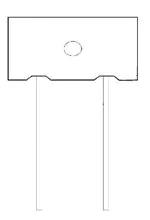
Dimensions – Millimeters (Inches)
Metric will govern
A CASE
B, C, & D CASES
W
W
0.015
(Stand Off)
H
H
E
E
0.500±0.125
(12.7±3.18)
0.015±0.005
(0.38±0.13)
(Stand Off)
0.020±0.001
(0.51±0.03)
0.500±0.125
(12.7±3.18)
0.025±0.001
(0.64±0.03)
S
S
T
0.050R±0.005
(1.27R±0.13)
T
Note: On the “B” case size the stand
off appears only between the two leads
Case Size
A
B
C
D
H
Case Height
W
Case Width
T Case
Thickness
E Case
to Wire
S
Lead Spacing
0.345 ±0.008
(8.76 ±0.203)
0.225 ±0.015
(5.71 ±0.38)
0.325 ±0.015
(8.26 ±0.38)
0.375 ±0.015
(9.53 ±0.38)
0.230 ±0.005
(5.84 ±0.127)
0.285 ±0.015
(7.24 ±0.38)
0.325 ±0.015
(8.26 ±0.38)
0.600 ±0.015
(15.24 ±0.38)
0.105 ±0.005
(2.67 ±0.127)
0.170 ±0.015
(4.32 ±0.38)
0.170 ±0.015
(4.32 ±0.38)
0.195 ±0.015
(4.95 ±0.38)
0.050 ±0.010
(1.27 ±0.25)
0.042 ±0.010
(1.07 ±0.25)
0.062 ±0.010
(1.57 ±0.25)
0.200 ±0.010
(5.08 ±0.25)
0.125 ±0.005
(3.18 ±0.127)
0.200 ±0.005
(5.08 ±0.127)
0.200 ±0.005
(5.08 ±0127)
0.200 ±0.005
(5.08 ±0.127)
© KEMET Electronics Corporation • P.O. Box 5928 • Greenville, SC 29606 • 864-963-6300 • www.kemet.com
T2040_T330 • 3/27/2018
3
�Tantalum Through-Hole Capacitors – Molded Radial
T330 Molded Radial
Table 1 – Ratings & Part Number Reference
Rated Voltage
Rated
Capacitance
(V) 85°C
µF
6
6
6
6
6
6
6
6
6
6
6
6
6
6
6
6
6
6
6
10
10
10
10
10
10
10
10
10
10
10
10
10
10
10
10
10
10
10
10
10
10
10
15
15
15
15
15
15
15
15
15
15
15
18.0
22.0
10.0
12.0
15.0
18.0
22.0
27.0
33.0
39.0
47.0
56.0
68.0
82.0
100.0
120.0
150.0
180.0
220.0
10.0
12.0
15.0
5.6
6.8
8.2
10.0
12.0
15.0
18.0
22.0
18.0
22.0
27.0
33.0
39.0
47.0
56.0
68.0
82.0
100.0
120.0
150.0
8.2
3.9
4.7
5.6
6.8
8.2
10.0
12.0
15.0
18.0
22.0
(V) 85°C
µF
Rated Voltage
Rated Capacitance
Case Code
KEMET Part Number
DC
Leakage
DF
A
A
B
B
B
B
B
C
C
C
C
C
C
D
D
D
D
D
D
A
A
A
B
B
B
B
B
B
B
B
C
C
C
C
C
D
D
D
D
D
D
D
A
B
B
B
B
B
C
C
C
C
C
(See below for
part options)
T330A186(1)006A(2)
T330A226(1)006A(2)
T330B106(1)006A(2)
T330B126(1)006A(2)
T330B156(1)006A(2)
T330B186(1)006A(2)
T330B226(1)006A(2)
T330C276(1)006A(2)
T330C336(1)006A(2)
T330C396(1)006A(2)
T330C476(1)006A(2)
T330C566(1)006A(2)
T330C686(1)006A(2)
T330D826(1)006A(2)
T330D107(1)006A(2)
T330D127(1)006A(2)
T330D157(1)006A(2)
T330D187(1)006A(2)
T330D227(1)006A(2)
T330A106(1)010A(2)
T330A126(1)010A(2)
T330A156(1)010A(2)
T330B565(1)010A(2)
T330B685(1)010A(2)
T330B825(1)010A(2)
T330B106(1)010A(2)
T330B126(1)010A(2)
T330B156(1)010A(2)
T330B186(1)010A(2)
T330B226(1)010A(2)
T330C186(1)010A(2)
T330C226(1)010A(2)
T330C276(1)010A(2)
T330C336(1)010A(2)
T330C396(1)010A(2)
T330D476(1)010A(2)
T330D566(1)010A(2)
T330D686(1)010A(2)
T330D826(1)010A(2)
T330D107(1)010A(2)
T330D127(1)010A(2)
T330D157(1)010A(2)
T330A825(1)015A(2)
T330B395(1)015A(2)
T330B475(1)015A(2)
T330B565(1)015A(2)
T330B685(1)015A(2)
T330B825(1)015A(2)
T330C106(1)015A(2)
T330C126(1)015A(2)
T330C156(1)015A(2)
T330C186(1)015A(2)
T330C226(1)015A(2)
(see below for
part options)
µA @ 25°C
Maximum/5 Minutes
1.0
1.0
1.0
1.0
1.0
1.0
1.0
1.0
1.0
1.0
2.0
5.0
5.0
5.0
5.0
5.0
5.0
10.0
10.0
1.0
1.0
1.0
1.0
1.0
1.0
1.0
1.0
1.0
1.0
2.0
1.0
2.0
2.0
2.0
5.0
5.0
5.0
5.0
5.0
10.0
10.0
10.0
1.0
1.0
1.0
1.0
1.0
1.0
1.0
1.0
2.0
5.0
5.0
µA @ 25°C
Maximum/5 Minutes
% @ 25°C
120 Hz Maximum
6
6
6
6
6
6
6
6
6
6
6
6
6
6
6
6
6
6
8
6
6
6
6
6
6
6
6
6
6
6
6
6
6
6
6
6
6
6
6
6
6
6
6
6
6
6
6
6
6
6
6
6
6
% @ 25°C
120 Hz Maximum
Case Code
KEMET Part Number
DC
Leakage
DF
(1) To complete KEMET part number, insert M for ±20%, K for ±10% or J for 5%. Designates Capacitance tolerance.
(2) To complete KEMET part number, insert T = 100% Matte Tin (Sn) Plated, S = Standard Solder coated (SnPb 5% Pb minimum).
Designates termination finish.
Higher voltage and better capacitance tolerance products may be substituted for an order within the same case size at KEMET's option.
© KEMET Electronics Corporation • P.O. Box 5928 • Greenville, SC 29606 • 864-963-6300 • www.kemet.com
T2040_T330 • 3/27/2018
4
�Tantalum Through-Hole Capacitors – Molded Radial
T330 Molded Radial
Table 1 – Ratings & Part Number Reference cont'd
Rated Voltage
Rated
Capacitance
(V) 85°C
µF
15
15
15
15
15
15
15
20
20
25
25
25
25
25
25
25
25
25
25
25
25
25
25
25
25
25
25
25
35
35
35
35
35
35
35
35
35
35
35
35
35
35
35
35
35
35
35
35
35
35
35
35
35
27.0
33.0
39.0
47.0
56.0
68.0
82.0
5.6
6.8
3.3
3.9
4.7
2.7
3.3
3.9
4.7
5.6
6.8
8.2
10.0
12.0
15.0
18.0
22.0
27.0
33.0
39.0
47.0
0.1
0.12
0.15
0.18
0.22
0.27
0.33
0.39
0.47
0.56
0.68
0.82
1.0
1.2
1.5
1.8
2.2
2.7
0.10
0.12
0.15
0.18
0.22
0.27
0.33
(V) 85°C
µF
Rated Voltage
Rated Capacitance
Case Code
KEMET Part Number
DC
Leakage
DF
C
C
D
D
D
D
D
A
A
A
A
A
B
B
B
B
C
C
C
C
C
C
D
D
D
D
D
D
A
A
A
A
A
A
A
A
A
A
A
A
A
A
A
A
A
A
B
B
B
B
B
B
B
(See below for
part options)
T330C276(1)015A(2)
T330C336(1)015A(2)
T330D396(1)015A(2)
T330D476(1)015A(2)
T330D566(1)015A(2)
T330D686(1)015A(2)
T330D826(1)015A(2)
T330A565(1)020A(2)
T330A685(1)020A(2)
T330A335(1)025A(2)
T330A395(1)025A(2)
T330A475(1)025A(2)
T330B275(1)025A(2)
T330B335(1)025A(2)
T330B395(1)025A(2)
T330B475(1)025A(2)
T330C565(1)025A(2)
T330C685(1)025A(2)
T330C825(1)025A(2)
T330C106(1)025A(2)
T330C126(1)025A(2)
T330C156(1)025A(2)
T330D186(1)025A(2)
T330D226(1)025A(2)
T330D276(1)025A(2)
T330D336(1)025A(2)
T330D396(1)025A(2)
T330D476(1)025A(2)
T330A104(1)035A(2)
T330A124(1)035A(2)
T330A154(1)035A(2)
T330A184(1)035A(2)
T330A224(1)035A(2)
T330A274(1)035A(2)
T330A334(1)035A(2)
T330A394(1)035A(2)
T330A474(1)035A(2)
T330A564(1)035A(2)
T330A684(1)035A(2)
T330A824(1)035A(2)
T330A105(1)035A(2)
T330A125(1)035A(2)
T330A155(1)035A(2)
T330A185(1)035A(2)
T330A225(1)035A(2)
T330A275(1)035A(2)
T330B104(1)035A(2)
T330B124(1)035A(2)
T330B154(1)035A(2)
T330B184(1)035A(2)
T330B224(1)035A(2)
T330B274(1)035A(2)
T330B334(1)035A(2)
(see below for
part options)
µA @ 25°C
Maximum/5 Minutes
5.0
5.0
10.0
10.0
10.0
10.0
10.0
1.0
1.0
1.0
1.0
1.0
1.0
1.0
1.0
1.0
1.0
1.0
1.0
1.0
1.0
2.0
5.0
5.0
5.0
5.0
10.0
10.0
1.0
1.0
1.0
1.0
1.0
1.0
1.0
1.0
1.0
1.0
1.0
1.0
1.0
1.0
1.0
1.0
1.0
1.0
1.0
1.0
1.0
1.0
1.0
1.0
1.0
µA @ 25°C
Maximum/5 Minutes
% @ 25°C
120 Hz Maximum
6
6
6
6
6
6
6
6
6
4
4
4
6
6
6
6
6
6
6
6
6
6
6
6
6
6
6
6
3
3
3
3
3
3
3
3
3
3
3
3
3
4
4
4
4
4
6
6
6
6
6
6
6
% @ 25°C
120 Hz Maximum
Case Code
KEMET Part Number
DC
Leakage
DF
(1) To complete KEMET part number, insert M for ±20%, K for ±10% or J for 5%. Designates Capacitance tolerance.
(2) To complete KEMET part number, insert T = 100% Matte Tin (Sn) Plated, S = Standard Solder coated (SnPb 5% Pb minimum).
Designates termination finish.
Higher voltage and better capacitance tolerance products may be substituted for an order within the same case size at KEMET's option.
© KEMET Electronics Corporation • P.O. Box 5928 • Greenville, SC 29606 • 864-963-6300 • www.kemet.com
T2040_T330 • 3/27/2018
5
�Tantalum Through-Hole Capacitors – Molded Radial
T330 Molded Radial
Table 1 – Ratings & Part Number Reference cont'd
Rated Voltage
Rated
Capacitance
(V) 85°C
µF
35
35
35
35
35
35
35
35
35
35
35
35
35
35
35
35
35
35
35
35
35
35
35
35
50
50
50
50
50
50
50
50
50
50
50
50
50
50
50
50
50
50
50
50
50
50
50
50
50
50
50
50
50
0.39
0.47
0.56
0.68
0.82
1.0
1.2
1.5
1.8
2.2
2.7
3.3
3.9
4.7
5.6
6.8
8.2
10.0
12.0
15.0
18.0
22.0
27.0
33.0
0.10
0.12
0.15
0.18
0.22
0.27
0.33
0.39
0.47
0.56
0.68
0.82
1.0
1.2
1.5
0.10
0.12
0.15
0.18
0.22
0.27
0.33
0.39
0.47
0.56
0.68
0.82
1.0
1.2
(V) 85°C
µF
Rated Voltage
Rated Capacitance
Case Code
KEMET Part Number
DC
Leakage
DF
B
B
B
B
B
B
B
B
B
B
B
B
C
C
C
C
C
C
D
D
D
D
D
D
A
A
A
A
A
A
A
A
A
A
A
A
A
A
A
B
B
B
B
B
B
B
B
B
B
B
B
B
B
(See below for
part options)
T330B394(1)035A(2)
T330B474(1)035A(2)
T330B564(1)035A(2)
T330B684(1)035A(2)
T330B824(1)035A(2)
T330B105(1)035A(2)
T330B125(1)035A(2)
T330B155(1)035A(2)
T330B185(1)035A(2)
T330B225(1)035A(2)
T330B275(1)035A(2)
T330B335(1)035A(2)
T330C395(1)035A(2)
T330C475(1)035A(2)
T330C565(1)035A(2)
T330C685(1)035A(2)
T330C825(1)035A(2)
T330C106(1)035A(2)
T330D126(1)035A(2)
T330D156(1)035A(2)
T330D186(1)035A(2)
T330D226(1)035A(2)
T330D276(1)035A(2)
T330D336(1)035A(2)
T330A104(1)050A(2)
T330A124(1)050A(2)
T330A154(1)050A(2)
T330A184(1)050A(2)
T330A224(1)050A(2)
T330A274(1)050A(2)
T330A334(1)050A(2)
T330A394(1)050A(2)
T330A474(1)050A(2)
T330A564(1)050A(2)
T330A684(1)050A(2)
T330A824(1)050A(2)
T330A105(1)050A(2)
T330A125(1)050A(2)
T330A155(1)050A(2)
T330B104(1)050A(2)
T330B124(1)050A(2)
T330B154(1)050A(2)
T330B184(1)050A(2)
T330B224(1)050A(2)
T330B274(1)050A(2)
T330B334(1)050A(2)
T330B394(1)050A(2)
T330B474(1)050A(2)
T330B564(1)050A(2)
T330B684(1)050A(2)
T330B824(1)050A(2)
T330B105(1)050A(2)
T330B125(1)050A(2)
(see below for
part options)
µA @ 25°C
Maximum/5 Minutes
1.0
1.0
1.0
1.0
1.0
1.0
1.0
1.0
1.0
1.0
1.0
1.0
1.0
1.0
1.0
2.0
5.0
5.0
5.0
5.0
10.0
10.0
10.0
10.0
1.0
1.0
1.0
1.0
1.0
1.0
1.0
1.0
1.0
1.0
1.0
1.0
1.0
1.0
1.0
1.0
1.0
1.0
1.0
1.0
1.0
1.0
1.0
1.0
1.0
1.0
1.0
1.0
1.0
µA @ 25°C
Maximum/5 Minutes
% @ 25°C
120 Hz Maximum
6
6
6
6
6
6
6
6
6
6
6
6
6
6
6
6
6
6
6
6
6
6
6
6
3
3
3
3
3
3
3
3
3
3
3
4
4
4
4
6
6
6
6
6
6
6
6
6
6
6
6
6
6
% @ 25°C
120 Hz Maximum
Case Code
KEMET Part Number
DC
Leakage
DF
(1) To complete KEMET part number, insert M for ±20%, K for ±10% or J for 5%. Designates Capacitance tolerance.
(2) To complete KEMET part number, insert T = 100% Matte Tin (Sn) Plated, S = Standard Solder coated (SnPb 5% Pb minimum).
Designates termination finish.
Higher voltage and better capacitance tolerance products may be substituted for an order within the same case size at KEMET's option.
© KEMET Electronics Corporation • P.O. Box 5928 • Greenville, SC 29606 • 864-963-6300 • www.kemet.com
T2040_T330 • 3/27/2018
6
�Tantalum Through-Hole Capacitors – Molded Radial
T330 Molded Radial
Table 1 – Ratings & Part Number Reference cont'd
Rated Voltage
Rated
Capacitance
(V) 85°C
µF
50
50
50
50
50
50
50
50
50
50
50
50
50
50
1.5
1.8
2.2
2.7
3.3
3.9
4.7
5.6
6.8
8.2
10.0
12.0
15.0
18.0
(V) 85°C
µF
Rated Voltage
Rated Capacitance
Case Code
KEMET Part Number
DC
Leakage
DF
B
B
B
C
C
C
C
C
D
D
D
D
D
D
(See below for
part options)
T330B155(1)050A(2)
T330B185(1)050A(2)
T330B225(1)050A(2)
T330C275(1)050A(2)
T330C335(1)050A(2)
T330C395(1)050A(2)
T330C475(1)050A(2)
T330C565(1)050A(2)
T330D685(1)050A(2)
T330D825(1)050A(2)
T330D106(1)050A(2)
T330D126(1)050A(2)
T330D156(1)050A(2)
T330D186(1)050A(2)
(see below for
part options)
µA @ 25°C
Maximum/5 Minutes
1.0
1.0
1.0
1.0
2.0
5.0
5.0
5.0
5.0
5.0
5.0
5.0
10.0
10.0
µA @ 25°C
Maximum/5 Minutes
% @ 25°C
120 Hz Maximum
6
6
6
6
6
6
6
6
6
6
6
6
6
6
% @ 25°C
120 Hz Maximum
Case Code
KEMET Part Number
DC
Leakage
DF
((1) To complete KEMET part number, insert M for ±20%, K for ±10% or J for 5%. Designates Capacitance tolerance.
(2) To complete KEMET part number, insert T = 100% Matte Tin (Sn) Plated, S = Standard Solder coated (SnPb 5% Pb minimum).
Designates termination finish.
Higher voltage and better capacitance tolerance products may be substituted for an order within the same case size at KEMET's option.
Recommended Voltage Derating Guidelines
85°C to 105°C
VR
66% of VR
120%
100%
% Working Voltage
% Change in working DC
voltage with temperature
−55°C to 85°C
80%
60%
% Change in working DC voltage
with temperature
67%
40%
20%
0%
-55
© KEMET Electronics Corporation • P.O. Box 5928 • Greenville, SC 29606 • 864-963-6300 • www.kemet.com
25
45
85
Temperature (°C)
105
125
T2040_T330 • 3/27/2018
7
�Tantalum Through-Hole Capacitors – Molded Radial
T330 Molded Radial
Ripple Current/Ripple Voltage
Permissible AC ripple voltage and current are related to
equivalent series resistance (ESR) and the power dissipation
capabilities of the device. Permissible AC ripple voltage that
may be applied is limited by following criteria:
1. Dissipated power must not exceed the limits specified
for the Series.
2. The positive peak AC voltage plus the DC bias voltage,
if any, must not exceed the DC voltage rating of the
capacitor.
3. The negative peak AC voltage in combination with
bias voltage, if any, must not exceed the allowable limits
specified for reverse voltage.
Thermal capacities for the various case sizes have been
determined empirically and are listed below. The “ripple
voltage” permissible may be calculated from the impedance
and ESR data shown in the respective product section.
Temperature Compensation Multipliers
for Maximum Power Dissipation
T ≤ 25°C
1.00
T ≤ 85°C
0.90
T ≤ 125°C
0.40
T= Environmental Temperature
Maximum allowable rms ripple voltage or current may be
determined as follows:
I(max) = √P max/R
E(max) = √P max/R
I = rms ripple current (amperes)
E = rms ripple voltage (volts)
P max = Maximum power dissipation (watts)
R = ESR at specified frequency (ohms)
Case Size
Maximum Power Dissipation
(Pmax) Watts at 25°C
A
B
C
D/F
0.09
0.09
0.100
0.125
Optimum Solder Wave Profile
Solder Wave Peak
Temperature 260ºC
Entrance to Solder Wave
Degrees – Cº
Flux Zone
250
225
200
175
150
125
100
75
50
25
Exit from Solder Wave
(Time in Wave – 2 to 4 Seconds)
Preheat Zone
Hot Air Debridging
Exit from
Solder
Machine
80ºC
to 120ºC
Entrance
to Solder
Machine
Free
Air
Cool
Bottom Side
Temperature
Range
Entrance to
In-Line Cleaner
Exit from
In-Line Cleaner
(time in cleaner
may be less)
Immersion in
Cleaning
Vapor
150ºC
Maximum
Top Side
Nominal
0
1
2
3
Time (Minutes)
4
5
© KEMET Electronics Corporation • P.O. Box 5928 • Greenville, SC 29606 • 864-963-6300 • www.kemet.com
6
T2040_T330 • 3/27/2018
8
�Tantalum Through-Hole Capacitors – Molded Radial
T330 Molded Radial
Reverse Voltage
Although these are polar capacitors, some degree of transient voltage reversal is permissible, as seen below.
The capacitors should not be operated continuously in reverse mode, even within these limits.
Temperature
Pecentage of Rated Voltage
+25°C
+85°C
+125°C
15
5
1
Mounting
All encased capacitors will pass the Resistance to Soldering Heat Test of MIL–STD–202, Method 210, Condition C. This test
simulates wave solder of topside board mount product. This demonstration of resistance to solder heat is in accordance
with what is believed to be the industry standard. More severe treatment must be considered reflective of an improper
soldering process. The above figure is a recommended solder wave profile for both axial and radial leaded solid tantalum
capacitors.
Capacitor Marking
Capacitance
Rated
Voltage
Tolerance:
5% - J
10% - K
20% - Standard (no mark)
KEMET
Trademark
Polarity
Storage
Tantalum molded radial/axial capacitors should be stored in normal working environments. KEMET recommends that
maximum storage temperature not exceed 40°C and maximum storage humidity not exceed 60°C RH. Storage at high
temperature may cause a small, temporary increase in leakage current (measured under standard conditions), but the
original value is usually restored within a few minutes after application of rated voltage. Storage at high humidity may
increase capacitance and dissipation factor. Solderability will be degraded by exposure to high temperatures, high humidity,
corrosive atmospheres, and long term storage. For optimized solderability capacitors stock should be used promptly,
preferably within three years of receipt.
© KEMET Electronics Corporation • P.O. Box 5928 • Greenville, SC 29606 • 864-963-6300 • www.kemet.com
T2040_T330 • 3/27/2018
9
�Tantalum Through-Hole Capacitors – Molded Radial
T330 Molded Radial
Tape & Reel Packaging Information
KEMET offers solid tantalum capacitors fully compatible for use with automatic insertion machines for radial-lead
components. Aris Reeling meets all requirements of EIA Standard RS-468. KEMET capacitors are wound on a precision
made ARIS Reel Package. ARIS Ammo Package is also available.
A1
P2
1
2
3
A
P
W2
F
W0
W
1
T370
2
T340**
3
T330**
D0
d
L1
T
P1
W1
H1
H
W2
P0
Dimension
Symbol
Nominal
mm (inch)
Tolerance
mm (inch)
Body Height (1)
A
10.50 (0.413)
±0.38 (±0.015) Maximum
Body Width (1)
A1
15.24 (0.600)
±0.38 (±0.015) Maximum
Sprocket Hole Diameter
D0
4.0 (0.157)
±0.3 (±0.012)
Lead Diameter
d
0.51 (0.020)
0.64 (0.025)
±0.05 (±0.001)
±0.03
Lead Center (5)
F
5.0 (0.197)
2.5 (0.098)
+0.8 (+0.032)
−0.2 (−0.008)
Component Base to Tape Center (2) (4) (6)
H
Lead Standoff Height
H0
Component Height Above Tape Center
H1
32.25 (1.270)
Maximum
Component Alignment Front to Rear
ΔH
0
±2.0 (±0.079)
Cut Out Length
L
11.0 (0.433)
Maximum
Lead Protrusion
L1
2.0 (0.079)
Maximum
Component Pitch (5)
P
12.7 (0.500)
±1.0 (±0.039)
Sprocket Hole Pitch (3)
P0
12.7 (0.500)
±0.03 (±0.012)
16.0 – 21.0 (0.630 – 0.827)
Reference Only
N/A
Sprocket Hole Center to Lead Center (4) (5)
P1
Sprocket Hole Center to Component Center
P2
3.85 (0.152)
6.35 (0.250)
4.76 (0.188)
±1.31 (±0.051)
Body Thickness
T0
6.35 (0.250)
±1.3 Maximum
Total Tape Thickness
T
0.7 (0.28)
±0.02(±0.008)
Carrier Tape Width
W
18.0 (0.709)
+1.0/−0.5 (+0.039/−0.020)
Hold-Down Tape Width
W0
Sprocket Hole Location
W1
Hold-Down Tape Location
W2
15 (0.561)
6 (0.236)
9.0 (0.354)
3.0 (0.118)
12.0 (0.472)
5.1 (0.201)
±0.7 (±0.028)
+1.0/−0.8 (+0.039/−0.031
+0.075/−0.5 (+0.030/−0.020)
Maximum
Notes: Reference only
Cumulative pitch error ±1.0 mm (0.039") maximum in 20 consecutive sprocket hole locations.
Measured at bottom of standoff.
P, P1 and F measured at egress from carrier tape.
The positive (+) lead exits from container first.
Lead spacings are 5.0 mm (0.197") center to center.
© KEMET Electronics Corporation • P.O. Box 5928 • Greenville, SC 29606 • 864-963-6300 • www.kemet.com
T2040_T330 • 3/27/2018
10
�Tantalum Through-Hole Capacitors – Molded Radial
T330 Molded Radial
Table 2 – Packaging Quantity
Case Size
Standard Bulk
Quantity
Standard Reel
Quantity
Reel C-Spec
Ammo Pack
Quantity
A
400
1,000
C-7301
1,600
B
300
1,000
C-7301
1,200
C
200
1,000
C-7301
1,200
D
100
N/A
N/A
N/A
© KEMET Electronics Corporation • P.O. Box 5928 • Greenville, SC 29606 • 864-963-6300 • www.kemet.com
T2040_T330 • 3/27/2018
11
�Tantalum Through-Hole Capacitors – Molded Radial
T330 Molded Radial
KEMET Electronics Corporation Sales Offices
For a complete list of our global sales offi ces, please visit www.kemet.com/sales.
Disclaimer
All product specifi cations, statements, information and data (collectively, the “Information”) in this datasheet are subject to change. The customer is responsible for
checking and verifying the extent to which the Information contained in this publication is applicable to an order at the time the order is placed.
All Information given herein is believed to be accurate and reliable, but it is presented without guarantee, warranty, or responsibility of any kind, expressed or implied.
Statements of suitability for certain applications are based on KEMET Electronics Corporation’s (“KEMET”) knowledge of typical operating conditions for such
applications, but are not intended to constitute – and KEMET specifi cally disclaims – any warranty concerning suitability for a specifi c customer application or use.
The Information is intended for use only by customers who have the requisite experience and capability to determine the correct products for their application. Any
technical advice inferred from this Information or otherwise provided by KEMET with reference to the use of KEMET’s products is given gratis, and KEMET assumes no
obligation or liability for the advice given or results obtained.
Although KEMET designs and manufactures its products to the most stringent quality and safety standards, given the current state of the art, isolated component
failures may still occur. Accordingly, customer applications which require a high degree of reliability or safety should employ suitable designs or other safeguards
(such as installation of protective circuitry or redundancies) in order to ensure that the failure of an electrical component does not result in a risk of personal injury or
property damage.
Although all product–related warnings, cautions and notes must be observed, the customer should not assume that all safety measures are indicted or that other
measures may not be required.
KEMET is a registered trademark of KEMET Electronics Corporation.
© KEMET Electronics Corporation • P.O. Box 5928 • Greenville, SC 29606 • 864-963-6300 • www.kemet.com
T2040_T330 • 3/27/2018
12
�