SOLID TANTALUM CHIP CAPACITORS
T496 SERIES—Fail-Safe Fused
FEATURES
•
•
•
•
•
•
•
•
Built-in fuse protects against damaging short
circuit failure mode
Precision-molded, laser-marked case
Symmetrical, compliant terminations
Taped and reeled per EIA 481-1
Case geometry and footprints equivalent to
Industrial Grade T491 Series. (Case sizes
B, C, D and X only)
100% Surge Current test on C, D, X sizes
Patented fuse assembly
Operating Temperature: -55˚C to +125˚C
Fuse actuation, 25�C: within 1 second at fault
currents of 4 amps and higher.
Continuous current capability: 0.75 amps
Post-actuation resistance,
25�C: 10 megohms minimum
Test tabs on the sides of the case bypass the
capacitor element to allow direct testing of the
fuse assembly.
RoHS Compliant & Leadfree Terminations (See
www.kemet.com for lead transition)
•
•
•
•
•
OUTLINE DRAWINGS
CATHODE (-) END
VIEW
SIDE VIEW
ANODE (+) END
VIEW
B
W
Test Tab
0.15(0.006) Max.
H
K
B
E
T
S
X
BOTTOM VIEW
F
P
S
G
R
A
L
Termination
cutout at
KEMETs
Option,
either end
DIMENSIONS — Millimeters (Inches)
CASE SIZE
KEMET
EIA
B
3528-21
C
6032-28
D
7343-31
X
7343-43
H
±
±
±
10
(.1
(.287 ± .012) (.169 ±
± .012)
± 0.20
K ± (.008)
± 0.1
1.1
(.043)
1.4
(.055)
1.5
(.059)
2.3
(.091)
2.2
(.087)
2.2
(.087)
2.4
(.094)
2.4
(.094)
S
± 0.3
0.8
(.031)
1.3
(.051)
1.3
(.051)
1.3
(.051)
± 0.15
B
(Ref) ±
(.016)
0.5
(.020)
0.5
(.020)
0.5
(.020)
X
(Ref)
±
(.004
P
(Ref)
R
1.0
1.0
1.0
A
G
E
T
(Ref) (Min) (Ref) (Ref)
2.1
1.8
2.2
(.083) (.071) (.087)
2.8
(.1
(.094)
3.5
(.138)
1.0
(.004 ±
(.067)
(.005) (.150) (.138) (.138)
Notes: 1. Metric dimensions govern.
2. (Ref) - Dimensions provided for reference only.
* Round glue pad: 2.9 ± 0.1mm (.114" ± .004") in diameter at KEMET’s option.
T496 Series – ORDERING INFORMATION
T 496 B 105 M 025 A S
Lead Material
Tantalum
Series
T - 100% Sn (Tin) Plated
H - Tin/Lead (SnPb - 5% Pb minimum)
**S - Not recommended for new designs
T496 - Precision Molded, Fail-safe
Failure Rate
Case Size
A - Not Applicable
B, C, D, X
Voltage
Capacitance Tolerance
Capacitance Picofarad Code
First two digits represent significant figures.
Third digit specifies number of zeros to follow.
*Part number
example:
T496B105M025AT
(14 digits - no(14
spaces).
See www.kemet.com
Part
Number
Example:
T496B105M025AS
digits
no spa es) for Pb Free transition.
** “S” Termination codes are converting from 90Sn/10 Pb to 100% tin finishes. Orders including “S” suffix
M - ± 20%
K - ± 10%
termination codes do not quarantee Pb-free product.
TYPICAL FUSE ACTUATION PROFILE
Current (Amps)
10
1
.0001
.001
.01
.1
1
10
Time (Seconds)
36
©KEMET Electronics Corporation, P.O. Box 5928, Greenville, S.C. 29606, (864) 963-6300
�SOLID TANTALUM CHIP CAPACITORS
T496 RATINGS & PART NUMBER REFERENCE
Capacitance µF
Case
Size
KEMET
Part Number
DCL µA
@ 25°C
Max.
DF
% @ +25°C
120 Hz.
Max.
ESR
Ω @ +25°C
100 kHz
Max.
4 Volt Rating at +85°C (2.7 Volt Rating at +125°C)
T496C686(1)004A(2)
2.7
6.0
4.0
8.0
T496C107(1)004A(2)
6.0
8.0
T496D157(1)004A(2)
8.8
8.0
T496D227(1)004A(2)
13.2
8.0
T496D337(1)004A(2)
T496X337(1)004A(2)
13.2
8.0
T496X477(1)004A(2)
18.8
8.0
**6 Volt Rating at +85°C (4 Volt Rating at +125°C)
0.5
6.0
B
T496B475(1)006A(2)
0.5
6.0
B
T496B685(1)006A(2)
0.6
6.0
B
T496B106(1)006A(2)
1.3
6.0
B
T496B226(1)006A(2)
0.9
6.0
C
T496C156(1)006A(2)
1.4
6.0
C
T496C226(1)006A(2)
2.0
6.0
C
T496C336(1)006A(2)
2.9
6.0
D
T496D476(1)006A(2)
2.9
6.0
*C
T496C476(1)006A(2)
4.1
6.0
D
T496D686(1)006A(2)
4.1
6.0
*C
T496C686(1)006A(2)
X
T496X107(1)006A(2)
6.0
8.0
6.0
8.0
D
T496D107(1)006A(2)
9.0
8.0
*D
T496D157(1)006A(2)
13.2
8.0
*D
T496D227(1)006A(2)
T496X227(1)006A(2)
13.2
8.0
*X
T496X337(1)006A(2)
19.8
8.0
*X
68.0
100.0
150.0
220.0
#330.0
330.0
#470.0
1.6
1.2
0.8
0.7
0.7
0.7
0.5
3.5
3.5
3.5
3.5
2.0
2.0
2.0
1.0
1.6
1.0
1.2
0.9
0.8
0.7
0.7
0.7
0.5
10 Volt Rating at +85°C (7 Volt Rating at + 125°C)
B
T496B335(1)010A(2)
0.5
6.0
0.5
6.0
B
T496B475(1)010A(2)
0.7
6.0
B
T496B685(1)010A(2)
1.0
6.0
C
T496C106(1)010A(2)
1.5
6.0
B
T496B156(1)010A(2)
1.5
6.0
C
T496C156(1)010A(2)
2.2
6.0
C
T496C226(1)010A(2)
3.3
6.0
D
T496D336(1)010A(2)
3.3
6.0
*C
T496C336(1)010A(2)
4.7
6.0
D
T496D476(1)010A(2)
4.7
6.0
*C
T496C476(1)010A(2)
X
T496X686(1)010A(2)
6.8
6.0
6.8
6.0
D
T496D686(1)010A(2)
10.0
8.0
D
T496D107(1)010A(2)
T496X157(1)010A92)
15.0
8.0
*X
15.0
8.0
*D
T496D157(1)010A(2)
T496X227(1)010A(2)
22.0
8.0
*X
16 Volt Rating at +85°C (10 Volt Rating at +125°C)
0.5
6.0
B
T496B225(1)016A(2)
0.5
6.0
B
T496B335(1)016A(2)
0.8
6.0
B
T496B475(1)016A(2)
1.1
6.0
C
T496C685(1)016A(2)
1.6
6.0
B
T496B106(1)016A(2)
1.6
6.0
C
T496C106(1)016A(2)
2.4
6.0
C
T496C156(1)016A(2)
3.6
6.0
D
T496D226(1)016A(2)
3.6
6.0
*C
T496C226(1)016A(2)
5.3
6.0
D
T496D336(1)016A(2)
X
T496X476(1)016A(2)
7.5
6.0
7.5
6.0
D
T496D476(1)016A(2)
*X
T496X107(1)016A(2)
16.0
8.0
3.3
4.7
6.8
10.0
15.0
15.0
22.0
33.0
33.0
47.0
#47.0
68.0
68.0
100.0
150.0
#150.0
#220.0
2.2
3.3
4.7
6.8
10.0
10.0
15.0
22.0
22.0
33.0
47.0
47.0
100.0
3.5
3.5
3.5
2.0
3.5
2.0
2.0
1.0
1.6
1.0
1.2
0.9
0.8
0.7
0.7
0.7
0.5
3.5
3.5
3.5
2.0
3.5
2.0
2.0
1.0
1.6
1.0
0.9
0.8
0.7
T496 SERIES CONSTRUCTION
Negative
Termination*
Silver Adhesive
Washer
Molded
Case
Polarity
Stripe (+)
Case
Size
Polarity
Bevel (+)
1.5
2.2
3.3
4.7
6.8
10.0
15.0
22.0
33.0
47.0
0.68
1.0
1.5
2.2
3.3
4.7
6.8
10.0
10.0
15.0
22.0
22.0
0.47
0.68
1.0
1.5
2.2
3.3
4.7
6.8
10.0
15.0
22.0
0.15
0.22
0.33
0.47
0.68
1.0
1.5
2.2
3.3
B
B
B
C
C
C
D
D
X
X
T496B155(1)020A(2)
T496B225(1)020A(2)
T496B335(1)020A(2)
T496C475(1)020A(2)
T496C685(1)020A(2)
T496C106(1)020A(2)
T496D156(1)020A(2)
T496D226(1)020A(2)
T496X336(1)020A(2)
T496X476(1)020A(2)
Weld
Mn02 Coat
(First Layer)
Carbon
Positive
Termination*
(Second Layer)
Silver Paint
(Third Layer)
Tantalum
Wire
*100% Tin
ESR
Ω @ +25°C
100 kHz
Max.
0.5
0.5
0.7
1.0
1.4
2.0
3.0
4.4
6.6
9.4
6.0
6.0
6.0
6.0
6.0
6.0
6.0
6.0
6.0
6.0
5.0
3.5
3.5
2.0
2.0
2.0
1.0
1.0
0.9
0.3
6.5
5.0
5.0
3.5
2.5
2.5
2.0
0.6
1.2
1.0
0.9
0.8
8.0
6.5
5.0
4.5
3.5
2.5
1.5
1.3
1.0
0.9
0.3
16.0
14.0
10.0
8.0
7.0
5.5
5.0
2.5
2.0
(1) To complete KEMET Part Number, insert M for ±20% tolerance or K for
±10% tolerance.
(2) To complete KEMET Part Number, insert lead material designation for
Ordering Information on page 36.
Higher voltage ratings and tighter capacitance tolerance product may
be substituted within the same size at KEMET’s option. Voltage substitutions will be marked with the higher voltage rating.
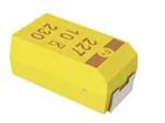
CAPACITOR MARKINGS
T496 Series — All Case Sizes
Fused
Fail-Safe
Device
Rated
Voltage
(Ta2O5)
DF
% @ +25°C
120 Hz.
Max.
25 Volt Rating at +85°C (17 Volt Rating at +125°C)
B
T496B684(1)025A(2)
0.5
4.0
0.5
4.0
B
T496B105(1)025A(2)
0.5
6.0
B
T496B155(1)025A(2)
0.6
6.0
C
T496C225(1)025A(2)
0.9
6.0
C
T496C335(1)025A(2)
1.2
6.0
C
T496C475(1)025A(2)
1.7
6.0
C
T496C685(1)025A(2)
2.5
6.0
C
T496C106(1)025A(2)
2.5
6.0
D
T496D106(1)025A(2)
3.8
6.0
D
T496D156(1)025A(2)
X
T496X226(1)025A(2)
5.5
6.0
5.5
6.0
D
T496D226(1)025A(2)
35 Volt Rating at +85°C (23 Volt Rating at +125°C)
B
T496B474(1)035A(2)
0.5
4.0
0.5
4.0
B
T496B684(1)035A(2)
0.5
4.0
B
T496B105(1)035A(2)
0.5
6.0
C
T496C155(1)035A(2)
0.8
6.0
C
T496C225(1)035A(2)
1.2
6.0
C
T496C335(1)035A(2)
1.7
6.0
D
T496D475(1)035A(2)
D
2.4
6.0
T496D685(1)035A(2)
X
T496X106(1)035A(2)
3.5
6.0
T496X156(1)035A(2)
5.3
6.0
*X
X
T496X226(1)035A(2)
7.7
6.0
50 Volt Rating at +85°C (33 Volt Rating at +125°C)
B
T496B154(1)050A(2)
0.5
4.0
0.5
4.0
B
T496B224(1)050A(2)
0.5
4.0
B
T496B334(1)050A(2)
0.5
4.0
C
T496C474(1)050A(2)
0.5
4.0
C
T496C684(1)050A(2)
0.5
4.0
C
T496C105(1)050A(2)
0.8
6.0
C
T496C155(1)050A(2)
1.1
6.0
D
T496D225(1)050A(2)
1.7
6.0
D
T496D335(1)050A(2)
Fuse
Tantalum
DCL µA
@ 25°C
Max.
KEMET
Part Number
20 Volt Rating at +85°C (13 Volt Rating at +125°C)
*C
*C
D
*D
*D
*X
*X
4.7
6.8
10.0
22.0
15.0
22.0
33.0
47.0
47.0
68.0
#68.0
100.0
100.0
150.0
#220.0
220.0
#330.0
Capacitance µF
F+
227
20K
542
Polarity
Indicator (+)
(Solid Stripe)
Picofarad
Code
KEMET
I. D. Symbol
Print Week Code:
1st Digit = Year
2nd & 3rd Digits = Week
"542" = The 42nd week of 2005
©KEMET Electronics Corporation, P.O. Box 5928, Greenville, S.C. 29606, (864) 963-6300
37
Solid Tantalum Surface Mount
T496 SERIES—Fail-Safe Fused
�TANTALUM AND ALUMINUM CHIP CAPACITORS
Packaging Information
Tape & Reel Packaging
KEMET’s Molded Tantalum and Aluminum Chip
Capacitor families are packaged in 8 mm and 12 mm plastic
tape on 7" and 13" reels, in accordance with EIA Standard
481-1: Taping of Surface Mount Components for Automatic
Handling. This packaging system is compatible with all tape
fed automatic pick and place systems.
Right Hand
Orientation
Only
(+)
Embossed Carrier
(–)
Embossment
8mm
±.30
8mm
(0.315")
(.315or±.012")
or
12mm
(0.472")
12mm
±.30
(.472 ±.012")
Top Tape Thickness
.10mm (.004") Max Thickness
178mm
(7.00")
180mm
(7.0")
oror
330mm
(13.00")
330mm
(13.0")
Labeling: Bar code labeling (standard or custom) shall be on the side of the reel opposite the sprocket holes.
Refer to EIA-556.
QUANTITIES PACKAGED PER REEL
Tape
Width-mm
8
8
8
12
12
12
8
8
12
12
12
12
12
7" Reel*
2,500
2,500
2,500
1,000
1,000
1,000
2,000
2,000
500
500
500
500
500
13" Reel*
10,000
10,000
10,000
5,000
3,000
3,000
9,000
8,000
3,000
2,500
2,000
2,000
2,000
Packaging
Case Code
KEMET
EIA
R
2012-12
S
3216-12
T
3528-12
U
6032-15
W
7343-15
V
7343-20
A
3216-18
B
3528-21
C
6032-28
D
7343-31
Y
7343-40
X
7343-43
E
7260-38
* No c-spec required for 7" reel packaging. C-7280 required for 13" reel packaging.
©KEMET Electronics Corporation, P.O. Box 5928, Greenville, S.C. 29606, (864) 963-6300
91
�TANTALUM, CERAMIC AND
ALUMINUM CHIP CAPACITORS
Packaging Information
Performance Notes
1. Cover Tape Break Force: 1.0 Kg Minimum.
2. Cover Tape Peel Strength: The total peel strength of the cover tape from the carrier tape shall be:
Tape Width
Peel Strength
8 mm
0.1 Newton to 1.0 Newton (10g to 100g)
12 mm
0.1 Newton to 1.3 Newton (10g to 130g)
The direction of the pull shall be opposite the direction of the carrier tape travel. The pull angle of the carrier
tape shall be 165� to 180� from the plane of the carrier tape. During peeling, the carrier and/or cover tape
shall be pulled at a velocity of 300 ±10 mm/minute.
3. Reel Sizes: Molded tantalum capacitors are available on either 180 mm (7") reels (standard) or 330 mm (13")
reels (with C-7280). Note that 13” reels are preferred.
4. Labeling: Bar code labeling (standard or custom) shall be on the side of the reel opposite the sprocket holes.
Refer to EIA-556.
Embossed Carrier Tape Configuration: Figure 1
Table 1 — EMBOSSED TAPE DIMENSIONS (Metric will govern)
Constant Dimensions — Millimeters (Inches)
Tape Size
8 mm
and
12 mm
D0
E
1.5
1.75 ±0.10
+0.10 -0.0
(0.059
(0.069 ±0.004)
+0.004, -0.0)
P0
P2
T Max
T1 Max
4.0 ±0.10
2.0 ±0.05
0.600
0.100
(0.157 ±0.004)
(0.079 ±0.002)
(0.024)
(0.004)
Variable Dimensions — Millimeters (Inches)
Tape Size
Pitch
B1 Max.
Note 1
D1 Min.
Note 2
F
P1
R Min.
Note 3
T2 Max
W
8 mm
Single
(4 mm)
4.4
1.0
3.5 ±0.05
4.0 ±0.10
25.0
2.5
8.0 ±0.30
(.315 ±0.012)
12 mm
Double
(8 mm)
(0.173)
(0.039) (0.138 ±0.002)
(0.157 ±0.004) (0.984)
(0.098)
8.2
(0.323)
1.5
5.5 ±0.05
(0.059) (0.217 ±0.002)
8.0 ±0.10
30.0
(0.315 ±0.004) (1.181)
4.6
12.0 ±0.30
(0.181) (0.472 ±0.012)
A0B0K0
Note 4
1. B1 dimension is a reference dimension for tape feeder clearance only.
2. The embossment hole location shall be measured from the sprocket hole controlling the location of the embossment. Dimensions of
embossment location and hole location shall be applied independent of each other.
3. Tape with components shall pass around radius “R” without damage (see sketch A). The minimum trailer length (Fig. 2) may require
additional length to provide R min. for 12 mm embossed tape for reels with hub diameters approaching N min. (Table 2)
4. The cavity defined by A0, B0, and K0 shall be configured to surround the part with sufficient clearance such that the chip does not protrude beyond the sealing plane of the cover tape, the chip can be removed from the cavity in a vertical direction without mechanical
restriction, rotation of the chip is limited to 20 degrees maximum in all 3 planes, and lateral movement of the chip is restricted to 0.5 mm
maximum in the pocket (not applicable to vertical clearance.)
©KEMET Electronics Corporation, P.O. Box 5928, Greenville, S.C. 29606, (864) 963-6300
93
Packaging
NOTES
�TANTALUM, CERAMIC AND
ALUMINUM CHIP CAPACITORS
Packaging Information
Embossed Carrier Tape Configuration (cont.)
Sketch D: Tape Camber (Top View)
1mm (0.039) Max.
1mm (0.039) Max.
250mm (9.843)
Allowable camber to be 1 mm/250 mm.
400mm (15.75) Min.
Figure 2:
Tape Leader
& Trailer
Dimensions
(Metric
Dimensions
Will Govern)
Figure 3: Reel Dimensions (Metric Dimensions will govern)
Table 2 – REEL DIMENSIONS (Metric will govern)
94
Tape Size
8 mm
A Max
330.0
(12.992)
B* Min
1.5
(0.059)
C
13.0 ± 0.20
(0.512 ± 0.008)
D* Min
20.2
(0.795)
12 mm
330.0
(12.992)
1.5
(0.059)
13.0 ± 0.20
(0.512 ± 0.008)
20.2
(0.795)
N Min
50.0
(1.969)
See
Note 3
Table 1
W1
8.4
+1.5, -0.0
(0.331
+0.059, -0.0)
12.4
+2.0, -0.0
(0.488
+0.078, -0.0)
W2 Max
14.4
(0.567)
18.4
(0.724)
©KEMET Electronics Corporation, P.O. Box 5928, Greenville, S.C. 29606, (864) 963-6300
W3
7.9 Min
(0.311)
10.9 Max
(0.429)
11.9 Min
(0.469)
15.4 Max
(0.606)
�


 工商网监
湘ICP备2023018690号
工商网监
湘ICP备2023018690号
