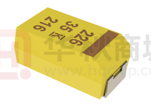
T498A475K016ATE3K0
T498, Tantalum, MnO2 Tantalum, High Temperature, 4.7 uF, 10%, 16 VDC,
SMD, MnO2, Molded, Hi-Temp, 150C, Auto, AEC-Q200, N/A, 3 Ohms, 3216,
Height Max = 1.8mm
General Information
Series
T498
Dielectric
MnO2 Tantalum
Style
SMD Chip
Description
SMD, MnO2, Molded, Hi-Temp, 150C, Auto,
AEC-Q200
Features
Automotive, 150C
RoHS
Yes
Termination
Tin
Qualifications
AEC-Q200
AEC-Q200
Yes
Component
Weight
58.6 mg
Shelf Life
156 Weeks
MSL
1
Click here for the 3D model.
Dimensions
Specifications
Capacitance
4.7 uF
Footprint
3216
L
3.2mm +/-0.2mm
Capacitance
Tolerance
10%
W
1.6mm +/-0.2mm
H
1.6mm +/-0.2mm
Voltage DC
16 VDC (85C), 12.75 VDC (125C), 10.72 VDC
(150C)
T
0.13mm REF
Temperature
Range
-55/+150°C
S
0.8mm +/-0.3mm
F
1.2mm +/-0.1mm
Rated
Temperature
85°C
A
1.2mm MIN
Dissipation Factor
4.5% 120Hz 25C
B
0.4mm +/-0.15mm
Failure Rate
N/A
E
1.3mm REF
Resistance
3000 mOhms (100kHz 25C)
G
1.1mm REF
Ripple Current
P
0.4mm REF
158 mA (rms, 100kHz 25C), 142.2 mA (rms,
85C), 47.4 mA (rms, 150C)
R
0.4mm REF
Leakage Current
0.8 uA (5min 25°C)
X
0.1mm +/-0.1mm
Packaging Specifications
Packaging
T&R, 178mm
Packaging Quantity
2000
Statements of suitability for certain applications are based on our knowledge of typical operating conditions for such applications, but are not intended to constitute - and we specifically disclaim - any
warranty concerning suitability for a specific customer application or use. This Information is intended for use only by customers who have the requisite experience and capability to determine the
correct products for their application. Any technical advice inferred from this Information or otherwise provided by us with reference to the use of our products is given gratis, and we assume no
obligation or liability for the advice given or results obtained.
Generated 8/29/2023 - 1c3fb08a-6a0e-4ca5-9c0b-16021bbe9b3b
© 2006 - 2023 KEMET
�T498A475K016ATE3K0
T498, Tantalum, MnO2 Tantalum, High Temperature, 4.7 uF, 10%, 16 VDC,
SMD, MnO2, Molded, Hi-Temp, 150C, Auto, AEC-Q200, N/A, 3 Ohms, 3216,
Height Max = 1.8mm
Simulations
For the complete simulation environment please visit K-SIM.
Generated 8/29/2023 - 1c3fb08a-6a0e-4ca5-9c0b-16021bbe9b3b
© 2006 - 2023 KEMET
�T498A475K016ATE3K0
T498, Tantalum, MnO2 Tantalum, High Temperature, 4.7 uF, 10%, 16 VDC,
SMD, MnO2, Molded, Hi-Temp, 150C, Auto, AEC-Q200, N/A, 3 Ohms, 3216,
Height Max = 1.8mm
Generated 8/29/2023 - 1c3fb08a-6a0e-4ca5-9c0b-16021bbe9b3b
© 2006 - 2023 KEMET
�T498A475K016ATE3K0
T498, Tantalum, MnO2 Tantalum, High Temperature, 4.7 uF, 10%, 16 VDC,
SMD, MnO2, Molded, Hi-Temp, 150C, Auto, AEC-Q200, N/A, 3 Ohms, 3216,
Height Max = 1.8mm
These are simulations.
This is not a specification!
The responses shown represent the typical response for each part type. Specific responses may vary, depending on manufacturing variation affects of all parameters involved, including the specified
tolerances applied to capacitance and unspecified variations of ESR, ESL, and leakage resistance.
The responses shown do not represent a specified or implied maximum capability of the device for all applications.
•
The ESR used for ripple “Ripple Current/Voltage vs. Frequency” plots is the ESR at ambient temperature.
•
The ESR in the “Temperature Rise vs. Ripple Current” plots is adjusted to each incremental temperature rise before the power and ripple current is calculated.
•
The effects shown herein are based on measured data from a multiple part sample of the parts in question.
•
Ripple capability of this device will be factored by thermal resistance (Rth) created by circuit traces (addi affects of all parameters involved, including the specified tolerances applied to
capacitance and unspecified variations of ESR, ESL, and leakage resistance.
The peak voltages generated in the “Temperature Rise vs. Combined Ripple Currents” plot are calculated for each frequency and are not combined with voltages generated at any other
harmonics.
Please consult with the catalog or field applications engineer for maximum capability of the device in specific applications.
•
•
All product information and data (collectively, the “Information”) are subject to change without notice.
KEMET K-SIM is designed to simulate behavior of components with respect to frequency, ambient temperature, and DC bias levels. The responses shown represent the typical response for each part
type. Specific responses may vary, depending on manufacturing variation effects of all parameters involved, including the specified tolerances applied to capacitance and unspecified variations of ESR,
ESL, and leakage resistance.
All Information given herein is believed to be accurate and reliable, but is presented without guarantee, warranty, or responsibility of any kind, expressed or implied. Statements of suitability for certain
applications are based on our knowledge of typical operating conditions for such applications, but are not intended to constitute – and we specifically disclaim – any warranty concerning suitability for a
specific customer application or use. This Information is intended for use only by customers who have the requisite experience and capability to determine the correct products for their application.
Any technical advice inferred from this Information or otherwise provided by us with reference to the use of our products is given gratis, and we assume no obligation or liability for the advice given or
results obtained.
If you have any questions please contact K-SIM.
Generated 8/29/2023 - 1c3fb08a-6a0e-4ca5-9c0b-16021bbe9b3b
© 2006 - 2023 KEMET
�