Thermal Sensors
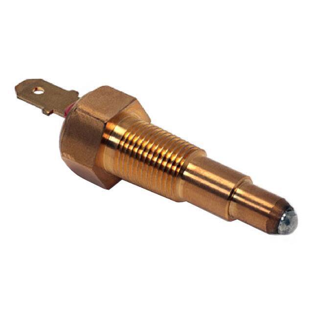
TRS Thermal Reed Switch, Screw Type
Overview
Applications
The TRS Thermal Reed Switch is a highly reliable, precise
temperature-sensitive switch ideal for energy conservation.
The screw mounting package of TRS-P makes it easy to set
up in the application, by just screwing it in the device that
needs temperature detection or overheat monitoring.
Typical applications include radiator water detection and
overheat detection for industrial and agricultural engines.
Its unique proprietary design features a magnet and
a temperature-sensing soft ferromagnetic substance
called Thermorite®. The material’s magnetic flux density
decreases as the temperature increases turning it into a
paramagnetic substance at the Curie temperature.
These products have also been attested by the International
Relay Association.
Benefits
• High reliability for on/off operations
• High-speed response
• Long operational life
• Excellent environmental durability
• Extremely simple circuit design with the screw mounting
• Compact, light, and easy to handle
TRS-P1 Type
• Dust, explosion and corrosion-proof
• Wide range of operating temperatures available
from 80°C to +120°C
• Excellent temperature accuracy of ±3°C
• RoHS/REACH compliant
TRS-P2 Type
Built Into Tomorrow
© KEMET Electronics Corporation • KEMET Tower • One East Broward Boulevard�
Fort Lauderdale, FL 33301 USA • 954-766-2800 • www.kemet.com
SE0219_TRS-P • 11/5/2021
1
�Thermal Sensors – TRS Thermal Reed Switch, Screw Type
Ordering Information
TRS
1-
80
M
PR
001
Series
Maximum
Opening/Closing
Power (W)
Operating Temperature (°C)
Contact Type
Shape
Classification
Lead Type
TRS
1 = 10 W
80 = 80°C
85 = 85°C
90 = 90°C
95 = 95°C
100 = 100°C
105 = 105°C
110 = 110°C
115 = 115°C
120 = 120°C
B = Break
M = Make
PR = P shape
PT screw
001 = PT1/8
002 = PT3/8
Structures and Principles of Operation
Thermal Reed Switches (TRSTM) are temperature-sensing switches composed of a magnet and a temperaturesensing soft ferromagnetic substance called ThermoriteTM. This material's saturation magnetic flux density
decreases
as the temperature
increases, and itof
turns
into a paramagnetic substance at the Curie temperature.
Structures
and Principles
Operation
Thermal Reed Switches (TRS) are temperature-sensing switches composed of a magnet and a temperature-sensing soft
ferromagnetic substance called Thermorite. This material’s saturation magnetic flux density decreases as the temperature
Temperature sensing ferrite(Thermorite Ⓡ)
increases, and it turns into a paramagnetic substance at its Curie temperature.
◆ Our self-developed Themorite is temperature sensing ferrite utilizing Curie-temperature,
where ferrites lose its magnetic property.
Thermorite
properties
Thermorite
changes
its magnetic property rapidly at Curie-temperature.
of
Thermorite
as temperature
sensing
material.rapidly at its Curie temperature, providing quick response times.
◆ Features
• Thermorite changes
its magnetic
property
(1) Curie-temperature do not vary as time advances, because it depends on compounding ratio.
• The Curie temperature of Thermorite does not vary with time, as it is based on a compounding ratio.
(2) Arbitrary shape available as ceramics.
Thermorite
is stable
againstgas.
moisture and hazardous gas.
(3) • Stable
against moist
or hazardous
Thermal property of Thermorite
Permeability - temperature
TC=60
TC=90
Permeability
TC=120
4000
3000
TC=150
2000
1000
0
20
40
60
80
100
120
140
160
3500
Saturation magnetic flux density
TC=30
5000
0
Saturation magnetic flux density ‒ temperature
(1kHz-0.01Oe)
6000
3000
2500
2000
TC=150
TC=90
1500
TC=60
1000
TC=120
TC=30
500
0
0
20
40
Temperature
(℃)
60
80
100
120
140
160
Temperature(℃)
TC=Curie temperature
Encasing
Structure of reed switch
◆ Reed switch is contact switch comprised of a pair of
Fe-Ni alloy reeds encased in glass tube
with inactive gas. The reeds are switched on or off
Inactive gas
by magnetic field of permanent magnet or magnet
coil.
◆ Long lifetime, High environmental resistance
because of protected contact by glass encasing.
N
◆ Reeds in glass tube become magnetized with
S
magnetic field, and then two reeds contact and
connect each other (switch on). And then magnetic
field© disappears,
the reeds separate and disconnect
KEMET Electronics Corporation • KEMET Tower • One East Broward Boulevard�
(switch
off).
Fort Lauderdale, FL 33301 USA • 954-766-2800 • www.kemet.com
Glass tube
Contact
Fe-Ni alloy reed
S
N
N
S
SE0219_TRS-P • 11/5/2021
2
�TC=150
2000
1000
Thermal Sensors – TRS Thermal Reed Switch, 0Screw Type
0
20
40
60
80
100
120
140
160
Saturation magneti
Permeabi
3000
2000
TC=60
1000
TC=120
TC=30
500
0
0
20
40
Temperature(℃)
60
80
100
120
140
160
Temperature(℃)
Structures and PrinciplesTC=Curie
of Operation
cont.
temperature
Reed switch structure
• The reed switch is a contact
switch
comprised
Structure
of reed
switch of a pair of Fe-Ni alloy
reeds encased in a glass
tube switch
with inactive
Thecomprised
reeds areofswitched
is contactgas.
switch
a pair of
◆ Reed
reeds encasedmagnet
in glass or
tube
on or off by the magneticFe-Ni
field alloy
of a permanent
magnet coil.
with inactive gas. The reeds are switched on or off
• The reeds in the glass tube
become magnetized from the magnetic
by magnetic field of permanent magnet or magnet
field, allowing the two reeds
coil.to make contact and connect (switch on).
Long lifetime,
resistance
When the magnetic field
the High
reedsenvironmental
separate and disconnect
◆disappears,
because of protected contact by glass encasing.
(switch off).
◆ Reeds in glass tube become magnetized with
• The glass encasement ofmagnetic
the reedsfield,
ensures
high environmental
and then two reeds contact and
resistance and a long operational
life.
connect each other (switch on). And then magnetic
TC=150
TC=90
1500
Encasing
Glass tube
Inactive gas
Contact
S
N
S
Fe-Ni alloy reed
N
N
S
field disappears, the reeds separate and disconnect
(switch off).
TRS principle: Break (B) type
TRS principle : Break (B) type
TRS principle : Break (B) type
( ■:Permanent magnet ■:Thermorite® ■:Reed switch contact area )
( ■:Permanent magnet ■:Thermorite® ■:Reed switch contact area )
Reset temperature
Action temperature
Reset temperature
Action temperature
Low temperature
Low temperature
Thermal magnet = paramagnet
Thermal magnet = paramagnet
N
N
S
S
S
S
N
N
S
S
N
N
S
S
N
N
S
S
N
N S
S
N
N
S
S
N
N
NEC TOKIN Sensors Vol.14 5
S
S
N
N
S N specifications
●All
in this catalog and production
products
S
N S status of N
S are subject to change without notice. Prior to the purchase, please contact NEC TOKIN for updated product data.
S N
Srequest for a specification sheet N
S
N data
S prior to the purchase.
●Please
for detailed
product
●Before using the product in this catalog, please read "Precautions" and other safety precautions listed in the printed version catalog.
N
N
<Magnetic Field of Contact Part>
<Magnetic Field of Contact Part>
Magnetic Flux Forming => Reed switch ON
Magnetic Flux Forming => Reed switch ON
S
S
High temperature
High temperature
Thermal magnet = NO magnetic
Thermal magnet = NO magnetic
N
N
S
S
<Magnetic Field of Contact Part>
<Magnetic Field of Contact Part>
Magnetic Flux ≒0 => Reed switch OFF
Magnetic Flux ≒0 => Reed switch OFF
2015.3.31 0000SENVOL14E1503H1
N
N
Switch ON
Switch ON
Switch OFF
Switch OFF
TRS principle: Make (M) type
TRS principle : Make (M) type
TRS principle : Make (M) type
( ■:Permanent magnet ■:Thermorite® ■:Gapspacer(SP) ■:Reed switch contact area )
( ■:Permanent magnet ■:Thermorite® ■:Gapspacer(SP) ■:Reed switch contact area )
Reset temperature
Action temperature
Reset temperature
Action temperature
Low temperature
Low temperature
High temperature
High temperature
Thermal magnet = paramagnet
Thermal magnet = paramagnet
Thermal magnet = NO magnetic
Thermal magnet = NO magnetic
N
N
S
S
N
N
S
S
S
S
S
S
N
N
N
N
S
S
N
N
S
S
S
S
N
N
N
N
S SP N
S SP N
S SP N
S SP N
S
S
S
S
N
N
N
N
<Magnetic Field of Contact Part>
<Magnetic Field of Contact Part>
Magnetic Flux ≒0 => Reed switch OFF
Magnetic Flux ≒0 => Reed switch OFF
S
S N
N
S
S
S
S
N
N
N
N
S
S
<Magnetic Field of Contact Part>
<Magnetic Field of Contact Part>
N
N
S
S
N
N
Switch OFF
Switch OFF
N
N
S
S
Switch ON
Switch ON
6 NEC TOKIN Sensors Vol.14
6 NEC TOKIN Sensors Vol.14
© KEMET Electronics Corporation • KEMET Tower • One East Broward Boulevard�
Fort Lauderdale, FL 33301 USA • 954-766-2800 • www.kemet.com
●All specifications in this catalog and production status of products are subject to change without notice. Prior to the purchase, please contact NEC TOKIN for updated product data.
●All
specifications
catalog and
production
status
of products
are to
subject
to change without notice. Prior to the purchase, please contact NEC TOKIN for updated product data.
●Please
request forinathis
specification
sheet
for detailed
product
data prior
the purchase.
●Please
request
a specification
sheet for
detailed
data prior
the purchase.
●Before using
theforproduct
in this catalog,
please
readproduct
"Precautions"
andtoother
safety precautions listed in the printed version catalog.
●Before using the product in this catalog, please read "Precautions" and other safety precautions listed in the printed version catalog.
2015.3.31 0000SENVOL14E1503H1
2015.3.31 0000SENVOL14E1503H1
SE0219_TRS-P • 11/5/2021
3
�External magnetic field
Thermal Sensors – TRS Thermal Reed Switch, Screw Type
TRS/OHD installation direction in external magnetic field
External Magnetic Field
Magnetic field emitting equipment
such as motors, coils
External
magnetic
fieldequipment
Magnetic
field from
TRS/OHD
installation in
direction
in external
magnetic
TRS Installation
External
Magnetic
Fieldfield
Magnetic field emitting equipment
such as motors, coils
Magnetic field from equipment
Wrong direction Correct direction
N
N
S
S
Wrong direction Correct direction
N
N
S
S
S
N
N
S
S
S
N
Magnet inside TRS is
perpendicular to the external field
→ Less influence
N
Magnet inside TRS is
parallel to the external field
→ Greater Influence
Magnet inside TRS is
parallel to the external field
→ Greater Influence
Magnet inside TRS is
perpendicular to the external field
→ Less influence
Ferromagnetic material influence
Operation temperature variation (°C)
Ferromagnetic Material Influence
3
2
Ferromagnetic
material influence
1
-2
-3
-4
-5
Operation temperature variation (°C)
0
-1
3
BType
2
MType
1
TRS
0
-1
-2
0
BType
2
4
-3
6
8
10
12
Gap distance_d(mm)
-4
-5
14
d
MType
Soft iron (thickness 3.3mm)
16
TRS
Note; Above figures are for reference only and are not guarantee d values.d
0
2
4
6
8
10
12
Gap distance_d(mm)
14
16
Soft iron (thickness 3.3mm)
TM
Before Using Thermal Reed Switch
(TRS
)
Note; Above figures are for reference only and are not guarantee d values.
• Please ask for a copy of specification and check the contents thoroughly before the actual use.
• Please contact us before deciding your specifications.
• Do not use in close proximity to strongly magnetized
parts.
TM
Before
Thermal
Reed Switch
(TRS
)
• Do not
useUsing
if dropped
or strongly
shocked.
• Please
forgreater
a copyload
of specifi
• Do NOT
useask
with
thancation
specifiand
ed. check the contents thoroughly before the actual use.
W h•ePlease
n i nstalcontact
l i ng thesus
e sbefore
wi tchedeciding
s i n ci rcuiyour
ts prospecifi
ne to cations.
produci ng surge vol tage ( i nducti ve l oad) or rush current
• Do not
usemotors),
in closean
proximity
to strongly
magnetized
parts.
(in lamps
and
appropriate
switch type
should be
used, or a contact point protection circuit added.
• A vo•iDo
d stnot
ress use
( espifecdropped
i al l y torsor
i onstrongly
) i n case shocked.
of addi ti onal processi ng.
NOT
use with
than specifi
ed.
• Each• Do
reed
switch
has agreater
specificload
resonance
frequency.
Please contact us when an oscillation is added.
W hen i nstal l i ng these swi tches i n ci rcui ts prone to produci ng surge vol tage ( i nducti ve l oad) or rush current
(in lamps and motors), an appropriate switch type should be used, or a contact point protection circuit added.
• A voi d stress ( especi al l y torsi on) i n case of addi ti onal processi ng.
NEC TOKIN Sensors Vol.14
7
• Each reed switch has a specific resonance frequency. Please contact us when an oscillation is added.
cifications in this catalog and production status ofopr
request for a specification sheet for detailed product
d
using the product in this catalog, please read "Precau
t
ducts are subject to change without notice. Prior to the purch
a
ata prior to the purchase
.
ions" and other safety precautions listed in the printed versi
o
© KEMET Electronics Corporation • KEMET Tower • One East Broward Boulevard�
NECNEC
TOKIN
Vol.14
7 .data
se, please contact
TOKINSensors
for updated
product
n catalog.
All specifications in this catalog and production status ofopr
ducts are subject to change without notice. Prior to the purch
a
Fort
FL 33301
USAproduct
• 954-766-2800
Please request
for aLauderdale,
specification sheet
for detailed
d
ata prior •towww.kemet.com
the purchase
.
Before using the product in this catalog, please read "Precau
t
ions" and other safety precautions listed in the printed versi
o
2015.3.31 0000SENVOL14E1503H
1
SE0219_TRS-P
• 11/5/2021
se, please contact NEC TOKIN for updated product .data
n catalog.
4
�Thermal Sensors – TRS Thermal Reed Switch, Screw Type
Dimensions – Millimeters
Part Type
Dimensions - Millimeters
2 1. 5
31
14
14
7
Epoxy Resin"Yellow"
Seal Processing
9 Minimum
1.5
8
5.5
3 Maximum
4
1~2.5
0.8
3
21.5
7
Epoxy Resin"Red"
PT1/8
34.5
14
14
φ7.7
φ6
φ10
5.5
Soldering
Lead Free
φ2
8
6.3
TRS1-***BPR001
8
9
3 Maximum
Seal Processing
9 Minimum
1.5
4
1~2.5
φ
0.8
3
22
17
PT1/8
φ7.7
φ6
φ10
5.5
Soldering
Lead Free
2
8
6.3
TRS1-***MPR001
37
7
Epoxy Resin"Green"
8
14
9 Minimum
9
Seal Processing
1~2.5
1.5
φ13
φ6
φ9.8
φ17.2
5.5
φ2
6. 3
8
TRS1-***BPR002
PT3/8
4
Soldering
Lead Free
0.8
3.5
22
17
37
7
Epoxy Resin"Blue"
11
Seal Processing
1~2.5
1.5
8
14
9 Minimum
φ13
φ6
φ9.8
φ17.2
5.5
φ
2
6. 3
8
TRS1-***MPR002
PT3/8
4
0.8
3.5
© KEMET Electronics Corporation • KEMET Tower • One East Broward Boulevard�
Fort Lauderdale, FL 33301 USA • 954-766-2800 • www.kemet.com
Soldering
Lead Free
SE0219_TRS-P • 11/5/2021
5
�Thermal Sensors – TRS Thermal Reed Switch, Screw Type
Environmental Compliance
All KEMET Thermal Sensors are RoHS compliant.
Performance Characteristics
Item
Operations
Performance Characteristics
All types
100,000 times
Condition
All types
1) Power supply voltage: 13.5 VDC
Connection load: lamp
Drive: On = 1 second, Off = 29 seconds
2) 14 VDC – 28 Ω (purely resistive load)
Judgement
All types
1) No stick
2) Contact resistance be within 500 mΩ
TRS-P1 type
7.35 N•m maximum (75 kgf•cm maximum)
Use a torque wrench or nut runner as a tightening tool
TRS-P2 type
34.3 N•m maximum (350 kgf•cm maximum)
Use a torque wrench or nut runner as a tightening tool
Screw Torque
Recommendation
Insulation & Temperature Characteristics
1
2
Shape
Type
Operating
Temperature
Range
Switching
Temperature
Range
Switching
Temperature
Precision1
Differential
Temperature2
P shape PT screw
−20°C to +130°C
80°C to +120°C
±3.0°C
10°C Maximum
Switching temperature precision does not include measurement error.
The differential temperature is also referred to as the hysteresis temperature on thermal sensors.
© KEMET Electronics Corporation • KEMET Tower • One East Broward Boulevard�
Fort Lauderdale, FL 33301 USA • 954-766-2800 • www.kemet.com
SE0219_TRS-P • 11/5/2021
6
�Thermal Sensors – TRS Thermal Reed Switch, Screw Type
Table 1 – Ratings & Part Number Reference
Part Number
1
Switching
Temperature
(°C)
Maximum
Differential
Temperature
(°C)
Contact
Type
Maximum
Opening/
Closing
Voltage (V)
Maximum
Opening/
Closing
Current1 (A)
Maximum
Opening/
Closing
Power1 (W)
Minimum
Opening/
Closing
Current
Maximum
Contact
Resistance
(mΩ)
Weight
(g)
TRS1-80BPR001
80°C ±3°C
10°C
Break
100 DC
0.500 DC
10.0 DC
5 mA/1 VDC
500
15.0
TRS1-85BPR001
85°C ±3°C
10°C
Break
100 DC
0.500 DC
10.0 DC
5 mA/1 VDC
500
15.0
TRS1-90BPR001
90°C ±3°C
10°C
Break
100 DC
0.500 DC
10.0 DC
5 mA/1 VDC
500
15.0
15.0
TRS1-95BPR001
95°C ±3°C
10°C
Break
100 DC
0.500 DC
10.0 DC
5 mA/1 VDC
500
TRS1-100BPR001
100°C ±3°C
10°C
Break
100 DC
0.500 DC
10.0 DC
5 mA/1 VDC
500
15.0
TRS1-105BPR001
105°C ±3°C
10°C
Break
100 DC
0.500 DC
10.0 DC
5 mA/1 VDC
500
15.0
TRS1-110BPR001
110°C ±3°C
10°C
Break
100 DC
0.500 DC
10.0 DC
5 mA/1 VDC
500
15.0
TRS1-115BPR001
115°C ±3°C
10°C
Break
100 DC
0.500 DC
10.0 DC
5 mA/1 VDC
500
15.0
TRS1-120BPR001
120°C ±3°C
10°C
Break
100 DC
0.500 DC
10.0 DC
5 mA/1 VDC
500
15.0
TRS1-80MPR001
80°C ±3°C
10°C
Make
100 DC
0.500 DC
10.0 DC
5 mA/1 VDC
500
16.2
TRS1-85MPR001
85°C ±3°C
10°C
Make
100 DC
0.500 DC
10.0 DC
5 mA/1 VDC
500
16.2
TRS1-90MPR001
90°C ±3°C
10°C
Make
100 DC
0.500 DC
10.0 DC
5 mA/1 VDC
500
16.2
TRS1-95MPR001
95°C ±3°C
10°C
Make
100 DC
0.500 DC
10.0 DC
5 mA/1 VDC
500
16.2
TRS1-100MPR001
100°C ±3°C
10°C
Make
100 DC
0.500 DC
10.0 DC
5 mA/1 VDC
500
16.2
TRS1-105MPR001
105°C ±3°C
10°C
Make
100 DC
0.500 DC
10.0 DC
5 mA/1 VDC
500
16.2
TRS1-110MPR001
110°C ±3°C
10°C
Make
100 DC
0.500 DC
10.0 DC
5 mA/1 VDC
500
16.2
TRS1-115MPR001
115°C ±3°C
10°C
Make
100 DC
0.500 DC
10.0 DC
5 mA/1 VDC
500
16.2
TRS1-120MPR001
120°C ±3°C
10°C
Make
100 DC
0.500 DC
10.0 DC
5 mA/1 VDC
500
16.2
TRS1-80BPR002
80°C ±3°C
10°C
Break
100 DC
0.500 DC
10.0 DC
5 mA/1 VDC
500
34.0
TRS1-85BPR002
85°C ±3°C
10°C
Break
100 DC
0.500 DC
10.0 DC
5 mA/1 VDC
500
34.0
TRS1-90BPR002
90°C ±3°C
10°C
Break
100 DC
0.500 DC
10.0 DC
5 mA/1 VDC
500
34.0
TRS1-95BPR002
95°C ±3°C
10°C
Break
100 DC
0.500 DC
10.0 DC
5 mA/1 VDC
500
34.0
TRS1-100BPR002
100°C ±3°C
10°C
Break
100 DC
0.500 DC
10.0 DC
5 mA/1 VDC
500
34.0
TRS1-105BPR002
105°C ±3°C
10°C
Break
100 DC
0.500 DC
10.0 DC
5 mA/1 VDC
500
34.0
TRS1-110BPR002
110°C ±3°C
10°C
Break
100 DC
0.500 DC
10.0 DC
5 mA/1 VDC
500
34.0
TRS1-115BPR002
115°C ±3°C
10°C
Break
100 DC
0.500 DC
10.0 DC
5 mA/1 VDC
500
34.0
TRS1-120BPR002
120°C ±3°C
10°C
Break
100 DC
0.500 DC
10.0 DC
5 mA/1 VDC
500
34.0
TRS1-80MPR002
80°C ±3°C
10°C
Make
100 DC
0.500 DC
10.0 DC
5 mA/1 VDC
500
35.0
TRS1-85MPR002
85°C ±3°C
10°C
Make
100 DC
0.500 DC
10.0 DC
5 mA/1 VDC
500
35.0
TRS1-90MPR002
90°C ±3°C
10°C
Make
100 DC
0.500 DC
10.0 DC
5 mA/1 VDC
500
35.0
TRS1-95MPR002
95°C ±3°C
10°C
Make
100 DC
0.500 DC
10.0 DC
5 mA/1 VDC
500
35.0
TRS1-100MPR002
100°C ±3°C
10°C
Make
100 DC
0.500 DC
10.0 DC
5 mA/1 VDC
500
35.0
TRS1-105MPR002
105°C ±3°C
10°C
Make
100 DC
0.500 DC
10.0 DC
5 mA/1 VDC
500
35.0
TRS1-110MPR002
110°C ±3°C
10°C
Make
100 DC
0.500 DC
10.0 DC
5 mA/1 VDC
500
35.0
TRS1-115MPR002
115°C ±3°C
10°C
Make
100 DC
0.500 DC
10.0 DC
5 mA/1 VDC
500
35.0
TRS1-120MPR002
120°C ±3°C
10°C
Make
100 DC
0.500 DC
10.0 DC
5 mA/1 VDC
500
35.0
Part Number
Switching
Temperature
(°C)
Maximum
Differential
Temperature
(°C)
Contact
Type
Maximum
Minimum
Maximum
Maximum
Maximum
Contact
Opening/Closing Opening/Closing Opening/Closing Opening/Closing
Power1 (W)
Current
Resistance (mΩ)
Voltage (V)
Current1 (A)
Weight
(g)
Lamp load (13.5 V – 3.4 W lamp), 50 VA, 0.5 A in rush 3 A.
© KEMET Electronics Corporation • KEMET Tower • One East Broward Boulevard�
Fort Lauderdale, FL 33301 USA • 954-766-2800 • www.kemet.com
SE0219_TRS-P • 11/5/2021
7
�Thermal Sensors – TRS Thermal Reed Switch, Screw Type
Marking
Lot Code 1112 445
Operating Temperature
Contact Type
(1) 2-3 digits
80 = 80°C
95 = 95°C
110 = 110°C
(2) 1 digit
B = Break
M = Make
(4) 2 digits
01 = January
09 = September
10 = October
11 = November
12 = December
(5) 1 digit
A = 2017
B = 2018
C = 2019
D = 2020
Except I and O
LOT
CODE
Month of the Year
Year
Packaging
Series
Packaging Type
Pieces per Package
Pieces per Box
TRS-P
Tray
100
100
Handling Precautions
Precautions to be taken when using Thermal Reed Switches
(Please read these precautions before using our products)
• Do NOT use in close proximity to strong magnetic parts.
• Do NOT use product under mechanical weight load.
• Do NOT use if dropped or severely shocked.
• Do NOT use with a greater load than specified.
• Avoid stress (especially torsion) in case of additional processing.
• Thermal Reed Switches have a specific resonance frequency.
Please contact a KEMET representative if an oscillation is added.
© KEMET Electronics Corporation • KEMET Tower • One East Broward Boulevard�
Fort Lauderdale, FL 33301 USA • 954-766-2800 • www.kemet.com
SE0219_TRS-P • 11/5/2021
8
�Thermal Sensors – TRS Thermal Reed Switch, Screw Type
KEMET Electronics Corporation Sales Offices
For a complete list of our global sales offices, please visit www.kemet.com/sales.
Disclaimer
All product specifications, statements, information and data (collectively, the “Information”) in this datasheet are subject to change. The customer is responsible for
checking and verifying the extent to which the Information contained in this publication is applicable to an order at the time the order is placed. All Information given
herein is believed to be accurate and reliable, but it is presented without guarantee, warranty, or responsibility of any kind, expressed or implied.
Statements of suitability for certain applications are based on KEMET Electronics Corporation’s (“KEMET”) knowledge of typical operating conditions for such
applications, but are not intended to constitute – and KEMET specifically disclaims – any warranty concerning suitability for a specific customer application or use.
The Information is intended for use only by customers who have the requisite experience and capability to determine the correct products for their application. Any
technical advice inferred from this Information or otherwise provided by KEMET with reference to the use of KEMET’s products is given gratis, and KEMET assumes no
obligation or liability for the advice given or results obtained.
Although KEMET designs and manufactures its products to the most stringent quality and safety standards, given the current state of the art, isolated component
failures may still occur. Accordingly, customer applications which require a high degree of reliability or safety should employ suitable designs or other safeguards
(such as installation of protective circuitry or redundancies) in order to ensure that the failure of an electrical component does not result in a risk of personal injury or
property damage.
Although all product–related warnings, cautions and notes must be observed, the customer should not assume that all safety measures are indicted or that other
measures may not be required.
When providing KEMET products and technologies contained herein to other countries, the customer must abide by the procedures and provisions stipulated in all
applicable export laws and regulations, including without limitation the International Traffic in Arms Regulations (ITAR), the US Export Administration Regulations
(EAR) and the Japan Foreign Exchange and Foreign Trade Act.
KEMET is a registered trademark of KEMET Electronics Corporation.
© KEMET Electronics Corporation • KEMET Tower • One East Broward Boulevard�
Fort Lauderdale, FL 33301 USA • 954-766-2800 • www.kemet.com
SE0219_TRS-P • 11/5/2021
9
�