TSM3D667M010AH6410D493 数据手册
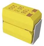
Tantalum Surface Mount Capacitors – Low ESR
Tantalum Stack MnO2 (TSM)
Overview
The KEMET Tantalum Stacks MnO2 (TSM) is designed
to provide the highest capacitance/voltage ratings in
surface mount configuration. KEMET's T493 COTS military/
aerospace capacitors are utilized in stacks of 2, 3, 4,and 6
components to achieve a broad range of capacitance and
voltage ratings. The T493 COTS offers component level
Weibull grading options, surge current testing options and
standard, low, and ultra-low ESR options. All component
level lots of this product are conditioned with MIL-PRF-55365
Group A testing. Stacking configurations offer this high
reliability product with custom capacitance/voltage solutions
and very low ESR options.
Note: Custom stacking solutions are available with other KEMET Tantalum
MnO2 Surface Mount products. Please contact KEMET Sales for availability.
Benefits
• High capacitance
• Surface mountable
• Capacitance values of 9.4 – 2,000 µF
• Capacitance can be custom specified
• Voltage ratings of 6 VDC to 50 VDC
• High volumetric efficiency
• Ultra-low ESR
• Surge capability
• Weibull failure options B and C
• Operating temperature range of −55˚C to +125˚C
• Laser-marked case
• Discrete components EIA standard case sizes (others available)
• High Temperature lead attach material available (> 260°C)
Click image above for interactive 3D content
Open PDF in Adobe Reader for full functionality
Applications
Typical applications include decoupling and filtering in a variety of market segments. The T493 COTS stack devices can be
utilized in military and aerospace applications. Other KEMET series can be utilized in filtering and decoupling applications to
service various market segments.
Environmental Compliance
RoHS Compliant (6/6) according to Directive 2002/95/EC when ordered with 100% Sn solder.
Built Into Tomorrow
© KEMET Electronics Corporation • KEMET Tower • One East Broward Boulevard
Fort Lauderdale, FL 33301 USA • 954-766-2800 • www.kemet.com
T2021_TSM • 1/8/2021
1
�Tantalum Surface Mount Capacitors – Low ESR
Tantalum Stack MnO2 (TSM)
K-SIM
For a detailed analysis of specific part numbers, please visit ksim.kemet.com to access KEMET’s K-SIM software. KEMET
K-SIM is designed to simulate behavior of components with respect to frequency, ambient temperature, and DC bias levels.
Ordering Information
T
SM
Capacitor
Class
Series
T=
Tantalum
Stacks
MnO2
cathode
2D
447
K
10
Rated
Case Capacitance Capacitance
Voltage
Size Code (pF)
Tolerance
(VDC)
K = ±10%
2C,
First two
M = ±20%
3C,
digits
4C,
represent
6C, significant
2D, figures. Third
3D, digit specifies
number of
4D,
zeros.
6D,
2X,
3X,
4X,
6X
006 = 6.3
010 = 10
016 = 16
020 = 20
025 = 25
035 = 35
050 = 50
A
H
61
20
D493
Failure
Rate/
Design
Termination
Finish
Surge
ESR
C-Spec 2
A = N/A
B = 0.1%/
1,000 hours
C = 0.01%/
1,000 hours
H = Standard
solder-coated
(SnPb 5% Pb
minimum)
C = Hot solder
dipped
B = Gold-plated
T = 100% Tin
61 = None
62 = 10 Cycles
25°C after
Weibull
63 = 10 cycles,
−55°C and 85°C
after Weibull
64 = 10 cycles,
−55°C and 85°C
before Weibull
10 = ESR standard
20 = ESR low
30 = ESR ultra-low
First digit
represents outer
leadframe finish
D = Silver-plated
(Ag)
H = Solder-plated
(SnPb 5% Pb
minimum)
T = 100% Tin (Sn)
Second, third,
and fourth digit
designates
discrete
component
series.
493 = T493
Note: Custom discrete component stacking solutions are also available with other KEMET Polymer Electrolytic Surface Mount series/products.
Please contact KEMET Sales for availability.
Performance Characteristics
Item
Performance Characteristics
Operating Temperature
Rated Capacitance Range
Capacitance Tolerance
Rated Voltage Range
−55°C to 125°C
9.4 – 2,000 μF at 120 Hz/25°C
K Tolerance (10%), M Tolerance (20%)
6 – 50 V
DF (120 Hz)
Refer to Part Number Electrical Specification Table
ESR (100 kHz)
Refer to Part Number Electrical Specification Table
Leakage Current
≤ 0.01 CV (µA) at rated voltage after 5 minutes
© KEMET Electronics Corporation • KEMET Tower • One East Broward Boulevard
Fort Lauderdale, FL 33301 USA • 954-766-2800 • www.kemet.com
T2021_TSM • 1/8/2021
2
�Tantalum Surface Mount Capacitors – Low ESR
Tantalum Stack MnO2 (TSM)
Qualification
Test
Condition
Characteristics
Δ C/C
Endurance
85°C at rated voltage, 2,000 hours
125°C at 2/3 rated voltage, 2,000 hours
Within initial limits
DCL
Within 1.25 x initial limit
ESR
Within initial limits
Δ C/C
Thermal Shock
KEMET specified test, mounted, −55°C to 125°C,
5 cycles
85°C, 1.15 x rated voltage 1,000 cycles
Within initial limits
DCL
Within 1.25 x initial limit
ESR
Within initial limits
Mechanical Vibration
125°C, 0.77 x rated voltage 1,000 cycles
MIL–STD–202, Method 204, Condition D, 10 Hz to
2,000 Hz, 20 G peak
© KEMET Electronics Corporation • KEMET Tower • One East Broward Boulevard
Fort Lauderdale, FL 33301 USA • 954-766-2800 • www.kemet.com
Within ±5% of initial value
DF
Within initial limits
DCL
Within initial limits
ESR
Within initial limits
Δ C/C
Surge Voltage
Within ±5% of initial value
DF
Δ C/C
Surge Voltage
Within ±10% of initial value
DF
Within ±5% of initial value
DF
Within initial limits
DCL
Within initial limits
ESR
Within initial limits
Δ C/C
Within ±10% of initial value
DF
Within initial limits
DCL
Within initial limits
T2021_TSM • 1/8/2021
3
�Tantalum Surface Mount Capacitors – Low ESR
Tantalum Stack MnO2 (TSM)
TSM2
TSP2
TSM2
TSP2
Dimensions – Millimeters (Inches)
Metric will govern
TSM2
L
W
H
W2
H2
P
2C
6.5±0.38
(0.258±0.015)
3.3±0.2
(0.130±0.008)
5.3±0.38
(0.210±0.015)
2.5±0.2
(0.100±0.008)
4.5±0.38
(0.176±0.015)
1.4±0.38
(0.055±0.015)
2D
8.0±0.38
(0.315±0.015)
4.4±0.2
(0.174±0.008)
6.2±0.38
(0.245±0.015)
3.0±0.2
(0.120±0.008)
4.8±0.38
(0.192±0.015)
1.9± .38
(0.075±0.015)
2X
8.0±0.38
(0.315±0.015)
4.4±0.2
(0.174±0.008)
8.9±0.38
(0.352±0.015)
3.0±0.2
(0.120±0.008)
6.9±0.38
(0.272±0.015)
1.9±0.38
(0.075±0.015)
L
W
H
W2
H2
P
3C
6.5±0.38
(0.258±0.015)
3.3±0.2
(0.130±0.008)
7.8±0.38
(0.310±0.015)
2.5±0.2
(0.100±0.008)
6.4±0.38
(0.252±0.015)
1.4±0.38
(0.055±0.015)
3D
8.0±0.38
(0.315±0.015)
4.4±0.2
(0.174±0.008)
9.2±0.38
(0.365±0.015)
3.0±0.2
(0.120±0.008)
7.7±0.38
(0.304±0.015)
1.9±0.38
(0.075±0.015)
TSM2 3X
TSP2
TSM2TSM4
TSP2
8.0±0.38
(0.315±0.015)
4.4±0.2
(0.174±0.008)
13.3±0.38
3.0±0.2
11.0±0.38
(0.525±0.015) (0.120 ±0.008) (0.436±0.015)
(0.075±0.015)
TSM4
TSP4
TSM4
TSP4
ANODE (+) END VIEW
L
W
ANODE (+) END VIEW
KEMET 4 Component
Stack Dimensions
SIDE VIEW
L
W
Case
Code
L
4C
6.5±0.38
(0.258±0.015)
6.6±0.2
(0.262±0.008)
H
5.3±0.38
(0.210±0.015)
P
8.0±0.38
(0.315±0.015)
8.0±0.38
(0.315±0.015)
4D
4X
WH
P
TSM3
TSP3TSM6
TSM3
TSP3
H2
P
5.8±0.2
(0.230±0.008)
4.6±0.38
(0.180±0.015)
1.4±0.38
(0.055±0.015)
8.9±0.2
(0.350±0.008)
H2
W2
6.2±0.38
7.4±0.2
(0.245±0.015) (0.292±0.008)
4.8±0.38
(0.192±0.015)
1.9±0.38
(0.075±0.015)
8.9±0.2
(0.350±0.008)
8.9±0.38
W2
(0.352±0.015)
7.4±0.2
6.9±0.38
(0.292±0.008) (0.272±0.015)
1.9±0.38
(0.075±0.015)
L
Case
Code
H2
ANODE (+) END VIEW
KEMET 6 Component Stack Dimensions
SIDE VIEW
L
L
W
ANODE (+) END VIEW
W
H
W
W2
H2
P
5.8±0.2
(0.230±0.008)
6.6±0.38
(0.260±0.015)
1.4±0.38
(.055±0.015)
6.5±0.38
(0.258±0.015)
6.6±0.2
(0.262±0.008)
7.8±0.38
(0.310±0.015)
6D
8.0±0.38
(0.315±0.015)
8.9±0.2
(0.350±0.008)
9.2±0.38
(0.365±0.015)
(0.292±0.008)
7.7±0.38
(0.304±0.015)
1.9±0.38
(0.075±0.015)
6X
8.0±0.38
(0.315±0.015)
8.9±0.2
H
(0.350±0.008)
13.3±0.38
(0.525±0.015)
7.4±0.2
11.0±0.38
(0.292±0.008)
(0.436±0.015)
H2
1.9±0.38
(0.075±0.015)
P
H2 7.4±0.2
W2
P
W
© KEMET Electronics
Corporation • KEMET Tower
• One East Broward Boulevard
Fort Lauderdale, FL 33301 USA • 954-766-2800 • www.kemet.com
2
H
P
P
W
W2
H2
W2
SIDE VIEW
ANODE (+) END VIEW
L
W
SIDE VIEW
ANODE (+) END VIEW
L
W
H
H2
H
H2
P
W2
SIDE VIEW
P
ANODE (+) END VIEW
L
W2
SIDE VIEW
L
W
ANODE (+) END VIEW
H
W
H2
H
P
W2
P
W2
TSM6
TSP6
TSM6
TSP6
6C
H
ANODE (+) END VIEW
H
1.9±0.38
W2
SIDE VIEW
H
W
H2
TSM3
TSP3
TSM3
TSP3
Case
Code
SIDE VIEW
L
L
Case
Code
KEMET 3 Component Stack Dimensions
ANODE (+) END VIEW
SIDE VIEW
KEMET 2 Component Stack Dimensions
TSM3
SIDE VIEW
SIDE VIEW
ANODE (+) END VIEW
L
W
SIDE VIEW
ANODE (+) END VIEW
L
W
H2
H
H2
H
H2
P
P
W2
T2021_TSM •W1/8/2021
2
4
�Tantalum Surface Mount Capacitors – Low ESR
Tantalum Stack MnO2 (TSM)
Capacitance & Rated Voltage Chart
Capacitance
Rated Voltage
µF
Code
6V
10 V
16 V
20 V
25 V
35 V
9.4
945
2D
14
146
3D
19
196
4D
20
206
28
286
30
306
2C
50 V
2X
6D
2C
3C
3X
4C
4X
40
406
44
446
45
456
3C
60
606
4C
66
666
3C
3D
88
886
4C
4D
90
906
94
946
130
137
140
147
3C
3D
190
197
4C
4D
200
207
270
277
280
287
300
307
3C
400
407
4C
2C
2D
6C
6X
6C
2C
2D
6C, 2D
2C
6D
3D
4D
6C
410
417
440
447
450
457
600
607
660
667
3C, 2D
3D, 2X
880
887
4C
4D
900
907
990
997
3D
3X
1300
138
6C, 4D
6D, 4X
2000
208
6D
6X
6D
2D
6D
2C
2D
3D
6C
4D
6D
© KEMET Electronics Corporation • KEMET Tower • One East Broward Boulevard
Fort Lauderdale, FL 33301 USA • 954-766-2800 • www.kemet.com
T2021_TSM • 1/8/2021
5
�Tantalum Surface Mount Capacitors – Low ESR
Tantalum Stack MnO2 (TSM)
Table 1A – TSM2 Ratings & Part Number Reference
Rated
Voltage
Rated
Capacitance
Case
Code/
Case Size
KEMET Part Number
VDC @ 85ºC
µF
KEMET/EIA
(See below for
part options)
6.3
10
16
20
25
35
6.3
10
16
20
25
35
50
10
50
440
200
94
44
30
20
660
440
300
130
94
44
9.4
660
20
2C
2C
2C
2C
2C
2C
2D
2D
2D
2D
2D
2D
2D
2X
2X
TSM2C447(1)006(2)(3)(4)(5)
TSM2C207(1)010(2)(3)(4)(5)
TSM2C946(1)016(2)(3)(4)(5)
TSM2C446(1)020(2)(3)(4)(5)
TSM2C306(1)025(2)(3)(4)(5)
TSM2C206(1)035(2)(3)(4)(5)
TSM2D667(1)006(2)(3)(4)(5)
TSM2D447(1)010(2)(3)(4)(5)
TSM2D307(1)016(2)(3)(4)(5)
TSM2D137(1)020(2)(3)(4)(5)
TSM2D946(1)025(2)(3)(4)(5)
TSM2D446(1)035(2)(3)(4)(5)
TSM2D945(1)050(2)(3)(4)(5)
TSM2X667(1)010(2)(3)(4)(5)
TSM2X206(1)050(2)(3)(4)(5)
DC
Leakage
DF
Standard
ESR
Low ESR
Ultralow ESR
µA at +25°C
Maximum/
5 Minutes
27.8
20.0
15.0
8.8
7.6
7.0
41.6
44.0
48.0
27.2
23.6
15.4
4.8
66.0
10.0
% at +25°C
120 Hz
Maximum
10
8
6
6
6
6
8
8
8
8
10
6
6
10
6
Ω at 25°C
100 kHz
Maximum
0.600
0.600
0.600
0.600
0.750
1.000
0.250
0.250
0.350
0.350
0.350
0.350
0.750
0.250
0.350
Ω at 25°C
100 kHz
Maximum
0.150
0.150
0.250
0.200
0.450
0.600
0.075
0.100
0.200
0.100
0.100
0.200
0.300
0.050
0.200
Ω at 25°C
100 kHz
Maximum
0.120
NA
0.175
NA
NA
NA
0.050
0.040
0.075
0.075
0.060
0.100
0.140
0.025
NA
Maximum
Operating
Temp
MSL
ºC
Reflow Temp
≤ 260ºC
125
125
125
125
125
125
125
125
125
125
125
125
125
125
125
1
1
1
1
1
1
1
1
1
1
1
1
1
1
1
Maximum
Operating
Temp
MSL
ºC
Reflow Temp
≤ 260ºC
125
125
125
125
125
125
125
125
125
125
125
125
125
125
125
1
1
1
1
1
1
1
1
1
1
1
1
1
1
1
Table 1B – TSM3 Ratings & Part Number Reference
Rated
Voltage
Rated
Capacitance
Case
Code/
Case Size
KEMET Part Number
VDC @ 85ºC
µF
KEMET/EIA
(See below for
part options)
6.3
10
16
20
25
35
6.3
10
16
20
25
35
50
10
50
660
300
140
66
45
30
990
660
450
200
140
66
14
990
30
3C
3C
3C
3C
3C
3C
3D
3D
3D
3D
3D
3D
3D
3X
3X
TSM3C667(1)006(2)(3)(4)(5)
TSM3C307(1)010(2)(3)(4)(5)
TSM3C147(1)016(2)(3)(4)(5)
TSM3C666(1)020(2)(3)(4)(5)
TSM3C456(1)025(2)(3)(4)(5)
TSM3C306(1)035(2)(3)(4)(5)
TSM3D997(1)006(2)(3)(4)(5)
TSM3D667(1)010(2)(3)(4)(5)
TSM3D457(1)016(2)(3)(4)(5)
TSM3D207(1)020(2)(3)(4)(5)
TSM3D147(1)025(2)(3)(4)(5)
TSM3D666(1)035(2)(3)(4)(5)
TSM3D146(1)050(2)(3)(4)(5)
TSM3X997(1)010(2)(3)(4)(5)
TSM3X306(1)050(2)(3)(4)(5)
DC
Leakage
DF
Standard
ESR
Low ESR
Ultralow ESR
µA at +25°C
Maximum/
5 Minutes
41.7
30.0
22.5
13.2
11.4
10.5
62.4
66.0
72.0
40.8
35.4
23.1
7.2
99.0
15.0
% at +25°C
120 Hz
Maximum
10
8
6
6
6
6
8
8
8
8
10
6
6
10
6
Ω at 25°C
100 kHz
Maximum
0.400
0.400
0.400
0.400
0.500
0.667
0.167
0.167
0.233
0.233
0.233
0.233
0.500
0.167
0.233
Ω at 25°C
100 kHz
Maximum
0.100
0.100
0.167
0.133
0.300
0.400
0.050
0.067
0.133
0.067
0.067
0.133
0.200
0.033
0.133
Ω at 25°C
100 kHz
Maximum
0.077
NA
0.117
NA
NA
NA
0.033
0.027
0.050
0.050
0.040
0.067
0.093
0.017
NA
(1) To complete KEMET part number, insert M for ± 20%, K for ± 10%. Designates Capacitance tolerance.
(2) To complete KEMET part number, insert B (0.1%/1,000 hours), C (0.01%/1,000 hours) or A = N/A. Designates Reliability Level.
(3) To complete KEMET part number, insert B = Gold Plated, C = Hot solder dipped, H = Solder Plated, or T = 100% Tin (Sn). Designates Termination
Finish.
(4) To complete KEMET part number, insert 61 = None, 62 = 10 cycles +25°C, 63 = 10 cycles -55°C +85°C after Weibull or 64 = 10 cycles -55°C +85°C
before Weibull. Designates Surge current option.
(5) To complete KEMET part number, insert 10 = Standard ESR, 20 = Low ESR or 30 = Ultra Low ESR. Designates ESR option.
Refer to Ordering Information for additional detail.
© KEMET Electronics Corporation • KEMET Tower • One East Broward Boulevard
Fort Lauderdale, FL 33301 USA • 954-766-2800 • www.kemet.com
T2021_TSM • 1/8/2021
6
�Tantalum Surface Mount Capacitors – Low ESR
Tantalum Stack MnO2 (TSM)
Table 1C – TSM4 Ratings & Part Number Reference
Rated
Voltage
Rated
Capacitance
Case
Code/
Case Size
KEMET Part Number
VDC @ 85ºC
µF
KEMET/EIA
(See below for
part options)
6.3
10
16
20
25
35
6.3
10
16
20
25
35
50
10
50
880
400
190
88
60
40
1300
880
600
270
180
88
19
1300
40
4C
4C
4C
4C
4C
4C
4D
4D
4D
4D
4D
4D
4D
4X
4X
TSM4C887(1)006(2)(3)(4)(5)
TSM4C407(1)010(2)(3)(4)(5)
TSM4C197(1)016(2)(3)(4)(5)
TSM4C886(1)020(2)(3)(4)(5)
TSM4C606(1)025(2)(3)(4)(5)
TSM4C406(1)035(2)(3)(4)(5)
TSM4D138(1)006(2)(3)(4)(5)
TSM4D887(1)010(2)(3)(4)(5)
TSM4D607(1)016(2)(3)(4)(5)
TSM4D277(1)020(2)(3)(4)(5)
TSM4D187(1)025(2)(3)(4)(5)
TSM4D886(1)035(2)(3)(4)(5)
TSM4D196(1)050(2)(3)(4)(5)
TSM4X138(1)010(2)(3)(4)(5)
TSM4X406(1)050(2)(3)(4)(5)
DC
Leakage
DF
Standard
ESR
Low ESR
Ultralow ESR
µA at +25°C
Maximum/
5 Minutes
55.6
40.0
30.0
17.6
15.2
14.0
83.2
88.0
96.0
54.4
47.2
30.8
9.6
132.0
20.0
% at +25°C
120 Hz
Maximum
10
8
6
6
6
6
8
8
8
8
10
6
6
10
6
Ω at 25°C
100 kHz
Maximum
0.300
0.300
0.300
0.300
0.375
0.500
0.125
0.125
0.175
0.175
0.175
0.175
0.375
0.125
0.175
Ω at 25°C
100 kHz
Maximum
0.075
0.075
0.125
0.100
0.225
0.300
0.038
0.050
0.100
0.050
0.050
0.100
0.150
0.025
0.100
Ω at 25°C
100 kHz
Maximum
0.058
NA
0.088
NA
NA
NA
0.025
0.020
0.038
0.038
0.030
0.050
0.070
0.013
NA
Maximum
Operating
Temp
MSL
ºC
Reflow Temp
≤ 260ºC
125
125
125
125
125
125
125
125
125
125
125
125
125
125
125
1
1
1
1
1
1
1
1
1
1
1
1
1
1
1
Maximum
Operating
Temp
MSL
ºC
Reflow Temp
≤ 260ºC
125
125
125
125
125
125
125
125
125
125
125
125
125
125
125
1
1
1
1
1
1
1
1
1
1
1
1
1
1
1
Table 1D – TSM6 Ratings & Part Number Reference
Rated
Voltage
Rated
Capacitance
Case
Code/
Case Size
KEMET Part Number
VDC @ 85ºC
µF
KEMET/EIA
(See below for
part options)
6.3
10
16
20
25
35
6.3
10
16
20
25
35
50
10
50
1300
600
280
130
90
60
2000
1300
900
410
280
130
28
2000
60
6C
6C
6C
6C
6C
6C
6D
6D
6D
6D
6D
6D
6D
6X
6X
TSM6C138(1)006(2)(3)(4)(5)
TSM6C607(1)010(2)(3)(4)(5)
TSM6C287(1)016(2)(3)(4)(5)
TSM6C137(1)020(2)(3)(4)(5)
TSM6C906(1)025(2)(3)(4)(5)
TSM6C606(1)035(2)(3)(4)(5)
TSM6D208(1)006(2)(3)(4)(5)
TSM6D138(1)010(2)(3)(4)(5)
TSM6D907(1)016(2)(3)(4)(5)
TSM6D417(1)020(2)(3)(4)(5)
TSM6D287(1)025(2)(3)(4)(5)
TSM6D137(1)035(2)(3)(4)(5)
TSM6D286(1)050(2)(3)(4)(5)
TSM6X208(1)010(2)(3)(4)(5)
TSM6X606(1)050(2)(3)(4)(5)
DC
Leakage
DF
Standard
ESR
Low ESR
Ultralow ESR
µA at +25°C
Maximum/
5 Minutes
83.4
60.0
45.0
26.4
22.8
21.0
124.8
132.0
144.0
81.6
70.8
46.2
14.4
198.0
30.0
% at +25°C
120 Hz
Maximum
10
8
6
6
6
6
8
8
8
8
10
6
6
10
6
Ω at 25°C
100 kHz
Maximum
0.200
0.200
0.200
0.200
0.250
0.333
0.083
0.083
0.117
0.117
0.117
0.117
0.250
0.083
0.117
Ω at 25°C
100 kHz
Maximum
0.050
0.050
0.083
0.067
0.150
0.200
0.025
0.033
0.067
0.033
0.033
0.067
0.100
0.017
0.067
Ω at 25°C
100 kHz
Maximum
0.038
NA
0.058
NA
NA
NA
0.017
0.013
0.025
0.025
0.020
0.033
0.047
0.008
NA
1) To complete KEMET part number, insert M for ± 20%, K for ± 10%. Designates Capacitance tolerance.
(2) To complete KEMET part number, insert B (0.1%/1,000 hours), C (0.01%/1,000 hours) or A = N/A. Designates Reliability Level.
(3) To complete KEMET part number, insert B = Gold Plated, C = Hot solder dipped, H = Solder Plated, or T = 100% Tin (Sn). Designates Termination
Finish.
(4) To complete KEMET part number, insert 61 = None, 62 = 10 cycles +25°C, 63 = 10 cycles -55°C +85°C after Weibull or 64 = 10 cycles -55°C +85°C
before Weibull. Designates Surge current option.
(5) To complete KEMET part number, insert 10 = Standard ESR, 20 = Low ESR or 30 = Ultra Low ESR. Designates ESR option.
Refer to Ordering Information for additional detail.
© KEMET Electronics Corporation • KEMET Tower • One East Broward Boulevard
Fort Lauderdale, FL 33301 USA • 954-766-2800 • www.kemet.com
T2021_TSM • 1/8/2021
7
�Tantalum Surface Mount Capacitors – Low ESR
Tantalum Stack MnO2 (TSM)
Recommended Voltage Derating Guidelines
120%
% Working Voltage
100%
80%
% Change in Working DC Voltage
with Temperature
67%
60%
40%
20%
Recommended Maximum
Application Voltage
(As % of Rated Voltage)
0%
−55
25
33%
85
Temperature (ºC)
125
Reverse Voltage
Solid tantalum capacitors are polar devices and may be permanently damaged or destroyed if connected with the wrong
polarity. The positive terminal is identified on the capacitor body by a stripe plus in some cases a beveled edge. A small
degree of transient reverse voltage is permissible for short periods per the table. The capacitors should not be operated
continuously in reverse mode, even within these limits.
Temperature
Permissible Transient Reverse Voltage
25°C
85°C
125°C
15% of Rated Voltage
5% of Rated Voltage
1% of Rated Voltage
© KEMET Electronics Corporation • KEMET Tower • One East Broward Boulevard
Fort Lauderdale, FL 33301 USA • 954-766-2800 • www.kemet.com
T2021_TSM • 1/8/2021
8
�Tantalum Surface Mount Capacitors – Low ESR
Tantalum Stack MnO2 (TSM)
Table 2 – Land Dimensions/Courtyard
KEMET
Density Level A:
Maximum (Most) Land Protrusion
(mm)
Density Level B:
Median (Nominal) Land Protrusion
(mm)
Density Level C:
Minimum (Least) Land Protrusion
(mm)
Case
L
W
S
V1
V2
L
W
S
V1
V2
L
W
S
V1
V2
TSM2C
2.98
2.74
2.53
9.50
4.50
2.58
2.62
2.73
8.40
4.00
2.20
2.52
2.89
7.54
3.74
TSM2D
3.48
3.24
3.03
11.00
5.60
3.08
3.12
3.23
9.90
5.10
2.70
3.02
3.39
9.04
4.84
TSM2X
3.48
3.24
3.03
11.00
5.60
3.08
3.12
3.23
9.90
5.10
2.70
3.02
3.39
9.04
4.84
TSM3C
2.98
2.74
2.53
9.50
4.50
2.58
2.62
2.73
8.40
4.00
2.20
2.52
2.89
7.54
3.74
TSM3D
3.48
3.24
3.03
11.00
5.60
3.08
3.12
3.23
9.90
5.10
2.70
3.02
3.39
9.04
4.84
TSM3X
3.48
3.24
3.03
11.00
5.60
3.08
3.12
3.23
9.90
5.10
2.70
3.02
3.39
9.04
4.84
TSM4C
2.98
6.04
2.53
9.50
7.80
2.58
5.92
2.73
8.40
7.30
2.20
5.82
2.89
7.54
7.04
TSM4D
3.48
7.64
3.03
11.00
10.10
3.08
7.52
3.23
9.90
9.60
2.70
7.42
3.39
9.04
9.34
TSM4X
3.48
7.64
3.03
11.00
10.10
3.08
7.52
3.23
9.90
9.60
2.70
7.42
3.39
9.04
9.34
TSM6C
2.98
6.04
2.53
9.50
7.80
2.58
5.92
2.73
8.40
7.30
2.20
5.82
2.89
7.54
7.04
TSM6D
3.48
7.64
3.03
11.00
10.10
3.08
7.52
3.23
9.90
9.60
2.70
7.42
3.39
9.04
9.34
TSM6X
3.48
7.64
3.03
11.00
10.10
3.08
7.52
3.23
9.90
9.60
2.70
7.42
3.39
9.04
9.34
Density Level A: For low-density Product applications. Recommended for wave solder applications and provides a wider process window for reflow
solder processes.
Density Level B: For products with a moderate level of component density. Provides a robust solder attachment condition for reflow solder processes.
Density Level C: For high component density product applications. Before adapting the minimum land pattern variations the user should perform
qualification testing based on the conditions outlined in IPC standard 7351 (IPC-7351).
1
Height of these chips may create problems in wave soldering.
V1
L
L
W
W
V2
S
Grid Placement Courtyard
© KEMET Electronics Corporation • KEMET Tower • One East Broward Boulevard
Fort Lauderdale, FL 33301 USA • 954-766-2800 • www.kemet.com
T2021_TSM • 1/8/2021
9
�Tantalum Surface Mount Capacitors – Low ESR
Tantalum Stack MnO2 (TSM)
Soldering Process
Please note that although the X/7343–43 case size can
withstand wave soldering, the tall profile (4.3 mm maximum)
dictates care in wave process development.
Hand soldering should be performed with care due to the
difficulty in process control. If performed, care should be
taken to avoid contact of the soldering iron to the molded
case. The iron should be used to heat the solder pad, applying
solder between the pad and the termination, until reflow
occurs. Once reflow occurs, the iron should be removed
immediately. “Wiping” the edges of a chip and heating the top
surface is not recommended.
During typical reflow operations, a slight darkening of the
gold-colored epoxy may be observed. This slight darkening is
normal and not harmful to the product. Marking permanency
is not affected by this change.
Profile Feature
SnPb Assembly Pb-Free Assembly
Preheat/Soak
Temperature Minimum (TSmin)
100°C
150°C
Temperature Maximum (TSmax)
150°C
200°C
Time (ts) from Tsmin to Tsmax)
60 – 120 seconds
60 – 120 seconds
Ramp-up Rate (TL to TP)
3°C/seconds maximum 3°C/seconds maximum
Liquidous Temperature (TL)
183°C
217°C
Time Above Liquidous (tL)
60 – 150 seconds
60 – 150 seconds
Peak Temperature (TP)
220°C*
250°C*
Time within 5°C of Maximum 20 seconds maximum 30 seconds maximum
Peak Temperature (tP)
Ramp-down Rate (TP to TL) 6°C/seconds maximum 6°C/seconds maximum
Time 25°C to Peak
6 minutes maximum
8 minutes maximum
Temperature
Note: All temperatures refer to the center of the package, measured on the
package body surface that is facing up during assembly reflow.
TP
TL
Temperature
KEMET’s families of surface mount capacitors are compatible
with wave (single or dual), convection, IR, or vapor phase
reflow techniques. Preheating of these components is
recommended to avoid extreme thermal stress. KEMET's
recommended profile conditions for convection and IR
reflow reflect the profile conditions of the IPC/J–STD–020D
standard for moisture sensitivity testing. The devices can
safely withstand a maximum of three reflow passes at these
conditions.
tP
Maximum Ramp-up Rate = 3°C/second
Maximum Ramp-down Rate = 6°C/second
tL
Tsmax
Tsmin
25
ts
25°C to Peak
Time
Storage
Tantalum chip capacitors should be stored in normal working environments. While the chips themselves are quite robust in
other environments, solderability will be degraded by exposure to high temperatures, high humidity, corrosive atmospheres,
and long term storage. In addition, packaging materials will be degraded by high temperature – reels may soften or warp
and tape peel force may increase. KEMET recommends that maximum storage temperature not exceed 40ºC and maximum
storage humidity not exceed 60% relative humidity. Temperature fluctuations should be minimized to avoid condensation on
the parts and atmospheres should be free of chlorine and sulphur bearing compounds. For optimized solderability chip stock
should be used promptly, preferably within three years of receipt.
© KEMET Electronics Corporation • KEMET Tower • One East Broward Boulevard
Fort Lauderdale, FL 33301 USA • 954-766-2800 • www.kemet.com
T2021_TSM • 1/8/2021
10
�Tantalum Surface Mount Capacitors – Low ESR
Tantalum Stack MnO2 (TSM)
Construction
Detailed Cross Section
Silver Paint
(Fourth Layer)
Tantalum Wire
Polarity
Stripe (+)
Molded Epoxy
Case
Leadframe
(− Cathode)
BeCu Alloy 190
Polarity
Bevel (+)
Lead Termination
(− Cathode)
Washer
Weld
(to attach wire)
High Temperature Solder
MnO2
Carbon
(Third Layer) (Second Layer)
Tantalum Wire
Ta2O5 Dielectric
(First Layer)
High Temperature Solder
Silver Adhesive
Molded Epoxy
Case
Washer
Tantalum
Leadframe
(+ Anode)
BeCu Alloy 190
Lead Termination
(+ Anode)
Solder Coated Alloy 752
Capacitor Marking
Date Code *
KEMET
Military
COTS
Polarity
Indicator (+)
1st digit = Last number of Year
2 = 2012
3 = 2013
4 = 2014
5 = 2015
6 = 2016
7 = 2017
2nd and 3rd digit = Week of the
Year
01 = 1st week of the Year to
52 = 52nd week of the Year
Picofarad
Code
KEMET
ID
Rated
Voltage
Date
Code*
* 230 = 30th week of 2012
© KEMET Electronics Corporation • KEMET Tower • One East Broward Boulevard
Fort Lauderdale, FL 33301 USA • 954-766-2800 • www.kemet.com
T2021_TSM • 1/8/2021
11
�Tantalum Surface Mount Capacitors – Low ESR
Tantalum Stack MnO2 (TSM)
KEMET Electronics Corporation Sales Offices
For a complete list of our global sales offi ces, please visit www.kemet.com/sales.
Disclaimer
All product specifi cations, statements, information and data (collectively, the “Information”) in this datasheet are subject to change. The customer is responsible for
checking and verifying the extent to which the Information contained in this publication is applicable to an order at the time the order is placed. All Information given
herein is believed to be accurate and reliable, but it is presented without guarantee, warranty, or responsibility of any kind, expressed or implied.
Statements of suitability for certain applications are based on KEMET Electronics Corporation’s (“KEMET”) knowledge of typical operating conditions for such
applications, but are not intended to constitute – and KEMET specifi cally disclaims – any warranty concerning suitability for a specifi c customer application or use.
The Information is intended for use only by customers who have the requisite experience and capability to determine the correct products for their application. Any
technical advice inferred from this Information or otherwise provided by KEMET with reference to the use of KEMET’s products is given gratis, and KEMET assumes
no obligation or liability for the advice given or results obtained.
Although KEMET designs and manufactures its products to the most stringent quality and safety standards, given the current state of the art, isolated component
failures may still occur. Accordingly, customer applications which require a high degree of reliability or safety should employ suitable designs or other safeguards
(such as installation of protective circuitry or redundancies) in order to ensure that the failure of an electrical component does not result in a risk of personal injury
or property damage.
Although all product–related warnings, cautions and notes must be observed, the customer should not assume that all safety measures are indicted or that other
measures may not be required.
KEMET is a registered trademark of KEMET Electronics Corporation.
© KEMET Electronics Corporation • KEMET Tower • One East Broward Boulevard
Fort Lauderdale, FL 33301 USA • 954-766-2800 • www.kemet.com
T2021_TSM • 1/8/2021
12
�