WP934MD/LYLID
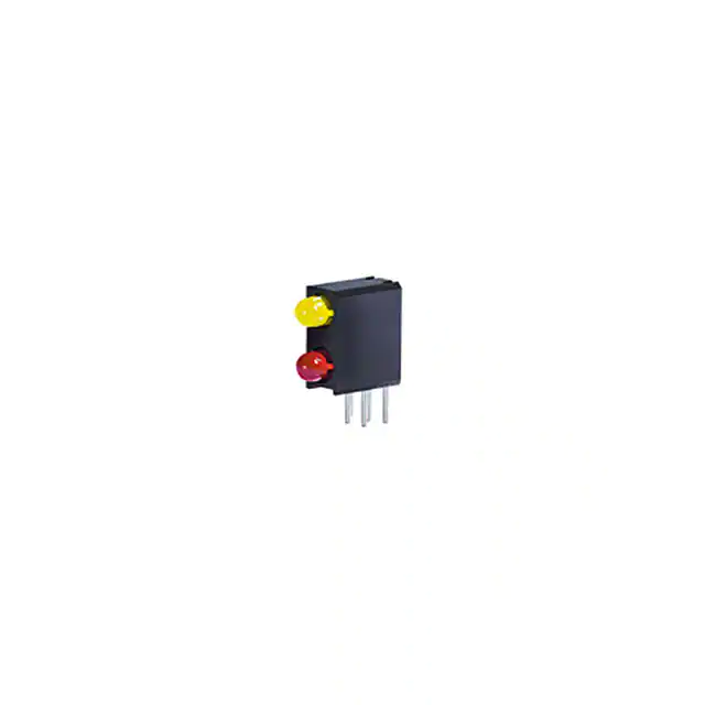
T-1 (3mm) Bi-Level Circuit Board Indicator
DESCRIPTIONS
�
�
PACKAGE DIMENSIONS
The Yellow source color devices are made with
Gallium Arsenide Phosphide on Gallium Phosphide
Yellow Light Emitting Diode
The High Efficiency Red source color devices are
made with Gallium Arsenide Phosphide on Gallium
Phosphide Orange Light Emitting Diode
LED1:Yellow
LED2:Red
FEATURES
�
�
�
�
�
�
Pre-trimmed leads for pc mounting
Black case enhances contrast ratio
High reliability life measured in years
Housing UL rating: 94V-0
Housing material: Type 66 nylon
RoHS compliant
APPLICATIONS
�
�
�
�
�
Status indicator
Illuminator
Signage applications
Decorative and entertainment lighting
Commercial and residential architectural lighting
Notes:
1. All dimensions are in millimeters (inches).
2. Tolerance is ±0.25(0.01") unless otherwise noted.
3. Lead spacing is measured where the leads emerge from the package.
4. The specifications, characteristics and technical data described in the datasheet are subject to change
without prior notice.
SELECTION GUIDE
Part Number
Emitting Color
(Material)
■ Yellow (GaAsP/GaP)
Iv (mcd) @ 2mA [2]
Viewing Angle [1]
Lens Type
Min.
Typ.
0.8
3
*0.8
*3
0.8
2
*0.5
*1.2
Yellow Diffused
2θ1/2
50°
WP934MD/LYLID
■ High Efficiency Red
Red Diffused
(GaAsP/GaP)
50°
Notes:
1. θ1/2 is the angle from optical centerline where the luminous intensity is 1/2 of the optical peak value.
2. Luminous intensity / luminous flux: +/-15%.
* Luminous intensity value is traceable to CIE127-2007 standards.
© 2021 Kingbright. All Rights Reserved. Spec No: DSAO7686 / 1102015364 Rev No: V.5A Date: 03/02/2021
Page 1 / 4
�WP934MD/LYLID
ELECTRICAL / OPTICAL CHARACTERISTICS at TA=25°C
Value
Parameter
Symbol
Emitting Color
Unit
Typ.
Max.
λpeak
Yellow
High Efficiency Red
590
627
-
nm
λdom [1]
Yellow
High Efficiency Red
588
617
-
nm
Spectral Bandwidth at 50% Φ REL MAX
IF = 2mA
∆λ
Yellow
High Efficiency Red
35
45
-
nm
Capacitance
C
Yellow
High Efficiency Red
20
15
-
pF
Forward Voltage IF = 2mA
VF [2]
Yellow
High Efficiency Red
1.85
1.7
2.2
2.1
V
Reverse Current (VR = 5V)
IR
Yellow
High Efficiency Red
-
10
10
µA
Temperature Coefficient of λpeak
IF = 2mA, -10°C ≤ T ≤ 85°C
TCλpeak
Yellow
High Efficiency Red
0.12
0.13
-
nm/°C
Temperature Coefficient of λdom
IF = 2mA, -10°C ≤ T ≤ 85°C
TCλdom
Yellow
High Efficiency Red
0.07
0.06
-
nm/°C
Temperature Coefficient of VF
IF = 2mA, -10°C ≤ T ≤ 85°C
TCV
Yellow
High Efficiency Red
-2
-1.9
-
mV/°C
Wavelength at Peak Emission IF = 2mA
Dominant Wavelength IF = 2mA
Notes:
1. The dominant wavelength (λd) above is the setup value of the sorting machine. (Tolerance λd : ±1nm. )
2. Forward voltage: ±0.1V.
3. Wavelength value is traceable to CIE127-2007 standards.
4. Excess driving current and / or operating temperature higher than recommended conditions may result in severe light degradation or premature failure.
ABSOLUTE MAXIMUM RATINGS at TA=25°C
Value
Parameter
Symbol
Unit
Yellow
High Efficiency Red
Power Dissipation
PD
75
75
mW
Reverse Voltage
VR
5
5
V
Junction Temperature
Tj
110
125
°C
Operating Temperature
Top
-40 to +85
°C
Storage Temperature
Tstg
-40 to +85
°C
DC Forward Current
IF
30
30
mA
IFM [1]
140
160
mA
Electrostatic Discharge Threshold (HBM)
-
8000
8000
V
Thermal Resistance (Junction / Ambient)
Rth JA [2]
690
680
°C/W
Thermal Resistance (Junction / Solder point)
Rth JS [2]
450
450
°C/W
Peak Forward Current
Lead Solder Temperature [3]
260°C For 3 Seconds
Lead Solder Temperature [4]
260°C For 5 Seconds
Notes:
1. 1/10 Duty Cycle, 0.1ms Pulse Width.
2. Rt h JA ,Rt h JS Results from mounting on PC board FR4 (pad size ≥ 16 mm 2 per pad).
3. 2mm below package base.
4. 5mm below package base.
5. Relative humidity levels maintained between 40% and 60% in production area are recommended to avoid the build-up of static electricity – Ref JEDEC/JESD625-A and JEDEC/J-STD-033.
© 2021 Kingbright. All Rights Reserved. Spec No: DSAO7686 / 1102015364 Rev No: V.5A Date: 03/02/2021
Page 2 / 4
�WP934MD/LYLID
TECHNICAL DATA
SPATIAL DISTRIBUTION
RELATIVE INTENSITY vs. WAVELENGTH
Yellow Red
Relative Intensity (a. u.)
100%
Ta = 25 °C
Ta = 25 °C
80%
0°
-15°
15°
30°
-30°
45°
-45°
60%
60°
-60°
40%
20%
75°
-75°
0%
350
400
450
500
550
600
Wavelength (nm)
650
700
750
800
-90°
1.0
0.5
0.0
90°
1.0
0.5
YELLOW
Forward current (mA)
Ta = 25 °C
8
6
4
2
1.7
1.8
1.9
2.0
Forward voltage (V)
10.0
Permissible forward current (mA)
Luminous intensity normalised at
2 mA
10
0
1.6
Forward Current Derating Curve
Luminous Intensity vs.
Forward Current
Ta = 25 °C
8.0
6.0
4.0
2.0
0.0
2.1
0
2
4
6
8
Forward current (mA)
50
Luminous Intensity vs.
Ambient Temperature
Luminous intensity normalised
at Ta = 25 °C
Forward Current vs.
Forward Voltage
40
30
20
10
0
10
2.5
2.0
1.5
1.0
0.5
0.0
-40 -20 0 20 40 60 80 100
Ambient temperature (°C)
-40 -20 0 20 40 60 80 100
Ambient temperature (°C)
HIGH EFFICIENCY RED
Forward current (mA)
Ta = 25 °C
8
6
4
2
1.6
1.7
1.8
1.9
Forward voltage (V)
10.0
Permissible forward current (mA)
Luminous intensity normalised at
2 mA
10
0
1.5
Forward Current Derating Curve
Luminous Intensity vs.
Forward Current
Ta = 25 °C
8.0
6.0
4.0
2.0
0.0
2.0
0
2
4
6
8
Forward current (mA)
10
50
Luminous Intensity vs.
Ambient Temperature
Luminous intensity normalised at
Ta = 25 °C
Forward Current vs.
Forward Voltage
40
30
20
10
0
-40 -20 0 20 40 60 80 100
Ambient temperature (°C)
2.5
2.0
1.5
1.0
0.5
0.0
-40 -20 0 20 40 60 80 100
Ambient temperature (°C)
RECOMMENDED WAVE SOLDERING PROFILE
Notes:
1. Recommend pre-heat temperature of 105°C or less (as measured with a thermocouple
attached to the LED pins) prior to immersion in the solder wave with a maximum solder bath
temperature of 260°C
2. Peak wave soldering temperature between 245°C ~ 255°C for 3 sec (5 sec max).
3. Do not apply stress to the epoxy resin while the temperature is above 85°C.
4. Fixtures should not incur stress on the component when mounting and during soldering process.
5. SAC 305 solder alloy is recommended.
6. No more than one wave soldering pass.
© 2021 Kingbright. All Rights Reserved. Spec No: DSAO7686 / 1102015364 Rev No: V.5A Date: 03/02/2021
Page 3 / 4
�WP934MD/LYLID
PACKING & LABEL SPECIFICATIONS
PRECAUTIONS
Storage Conditions
1. Avoid continued exposure to the condensing moisture environment and keep the product away from rapid transitions in ambient
temperature.
2. LEDs should be stored with temperature ≤ 30°C and relative humidity < 60%.
3. Product in the original sealed package is recommended to be assembled within 72 hours of opening.
Product in opened package for more than a week should be baked for 30 (+10/-0) hours at 85 ~ 100°C.
LED Mounting Method
1. The lead pitch of the LED must match the
pitch of the mounting holes on the PCB
during component placement.
Lead-forming may be required to insure
the lead pitch matches the hole pitch.
Refer to the figure below for proper lead
forming procedures.
Note 1-3: Do not route PCB trace in the contact area between the
leadframe and the PCB to prevent short-circuits.
" ○" Correct mounting method " x " Incorrect mounting method
Lead Forming Procedures
1. During soldering, component covers and holders should leave
clearance to avoid placing damaging stress on the LED during
soldering.
2. The tip of the soldering iron should never touch the lens epoxy.
3. Through-hole LEDs are incompatible with reflow soldering.
4. If the LED will undergo multiple soldering passes or face other
processes where the part may be subjected to intense heat,
please check with Kingbright for compatibility.
PRECAUTIONARY NOTES
1. The information included in this document reflects representative usage scenarios and is intended for technical reference only.
2. The part number, type, and specifications mentioned in this document are subject to future change and improvement without notice. Before production usage customer should refer to
the latest datasheet for the updated specifications.
3. When using the products referenced in this document, please make sure the product is being operated within the environmental and electrical limits specified in the datasheet. If
customer usage exceeds the specified limits, Kingbright will not be responsible for any subsequent issues.
4. The information in this document applies to typical usage in consumer electronics applications. If customer's application has special reliability requirements or have life-threatening
liabilities, such as automotive or medical usage, please consult with Kingbright representative for further assistance.
5. The contents and information of this document may not be reproduced or re-transmitted without permission by Kingbright.
6. All design applications should refer to Kingbright application notes available at https://www.KingbrightUSA.com/ApplicationNotes
© 2021 Kingbright. All Rights Reserved. Spec No: DSAO7686 / 1102015364 Rev No: V.5A Date: 03/02/2021
Page 4 / 4
�
很抱歉,暂时无法提供与“WP934MD/LYLID”相匹配的价格&库存,您可以联系我们找货
免费人工找货- 国内价格 香港价格
- 1+9.725801+1.23870
- 10+6.7871010+0.86440
- 100+5.02610100+0.64010
- 500+4.24480500+0.54060
- 1000+3.988301000+0.50800
- 2500+3.766702500+0.47970
- 5000+3.580105000+0.45600
- 10000+3.3469010000+0.42630
- 25000+3.2652025000+0.41590


 工商网监
湘ICP备2023018690号
工商网监
湘ICP备2023018690号