Users Manual
KAS-33100-003
“Walleye” Microphone
Evaluation Kit
�KAS-33100-003
Kit Description
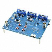
The KAS-33100-003 Walleye microphone
evaluation kit allows for simple and easy
evaluation of SiSonic™ MEMS microphones.
This evaluation system can be used to evaluate
up to 2 channels of audio for multiple MEMS
microphone types. Microphone types include
single ended and differential Analog MEMS
microphones, Digital PDM MEMS microphones,
and Digital I2S MEMS microphones.
Walleye Evaluation Board
The intended use is for the evaluation
and testing of the Knowles Electronics’ line
of MEMS microphones.
The board is designed to support R&D activities,
and is not intended for qualification or
production test use.
The Walleye board provides the interface circuitry
for 1 or 2 analog, 1 or 2 digital PDM, or 1 or 2 I2S
digital microphones.
Note: The Walleye board can pass mono or stereo audio of the
same microphone types (i.e. 2 digital PDM mics). The Walleye
board cannot pass audio of mixed types simultaneously.
For Walleye board information and documentation
visit the Knowles website.
www.Knowles.com/EvaluationKit_KA-33100
2
Kit Contents
• K
� AS-701004 WALLEYE Microphone
Evaluation Board Assembly.
• USB A type to Mini B type cable.
• F
� lex Adapter assembly part# KCA2733-D
(3 Total).
• SPH0644LM4H (bottom port
PDM) on flex (2 Total).
• SPK0641HT4H (top port PDM)
on flex (2 Total).
• S
� PH1642HT5H/V2 (top port analog)
on flex (2 Total).
• SPH0611LR5H (bottom port analog)
on flex (2 Total).
• SPH0645LM4H (bottom port I2S)
on flex (2 Total).
�Walleye Microphone Evaluation Kit
Block Diagrams
Power Supplies
Fig 1
5V0
VBUS
LM3658
BAT CHRGR
3V3
RT6150
5V Boost
800mA
OFF/ON
2V5
FAN2558
3.3V
FAN2558
2.5V
EN
EN
PG
1V8
FAN2558
1.8V
PG
+2V5
PG
EN
PG
MIC_VDD
MIC VDD Select
3V3
2V5
MIC_VDD
1V8
ADAU7002
PDM-I2S
uA
MIC Current
D
D
D
Dual I2S Mic
Test Jumper
EXT.
VDD
1.65-4V
A
D
VL
CS42L51
TC7SZ17
12.288
MHz
OSC
A
RESET Va
Dual Digital Mic
Test Jumper
Vd
PG
Audio Routing
External Clock Input
Fig 2
CS42L51
TC7SZ17
CLK
ADAU7002
PDM-I2S
12.288MHz
OSC
MCLK
CLK Source Jmpr
AOUTB
DATA
DIG
I2S
ANALOG
PDM
PCM2900
MIC SEL SW
AINR
AINL
DATA IN
+2.5V
DATA OUT
USB
CODEC
M/S* SEL
PDM
+2.5V
BCLK DIV
BY 2 Jmpr
Audio Out
AOUTA
SCLK
LRCLK
CLKDIV2
VBUS
D+
DGND
USB
Conn
Reset
Mute
Vol+
Vol-
I2S
AMIC1
ANALOG
I2S
AMIC2
ANALOG
www.knowles.com
3
�KAS-33100-003
DIGITAL MIC2 I2S MIC1
ANALOG MIC1 ANALOG MIC2 DIGITAL MIC1
I2S MIC2
Fig 3
10
10
9
9
7
8
8
DUAL MIC
TEST JUMPERS
7
6
11
AUDIO OUT
4
MIC CURRENT
MIC VDD
VOLTAGE LEVEL
SELECTOR
5
11
15
12
16
EXTERNAL CLOCK
INPUT BNC
MICROPHONE
TYPE SELECTOR
DE-EMPHASIS
FILTER JUMPER
BCLK JUMPER
EXTERNAL VDD
INPUT BNC
13
3
14
PC AUDIO
CONTROLS
2
1
LI ION BATTERY
INDICATORS (OPTIONAL)
WALLEYE BOARD
MAIN POWER SWITCH
MINI B
USB CONNECTOR
Functional Descriptions
1. Walleye Board Main Power Switch
Slide switch. When placed in the ON position will enable the internal voltage regulators and support
circuitry. If all internal supplies power up correctly the POWER GOOD LED will turn on.
2. Li ion Battery (Optional)
Note: If an optional 3.7V polymer lithium battery is installed the Li ion Battery will be charging when the
USB cable is connected regardless of the Main Power switch position. This will be indicated through the
CHRG LED. When charging is complete the FULL LED will light. Battery charging is limited to 100mA of
current from the connected PC. A full battery charge cycle can take up to 8 hours.
A full battery should have enough power to allow operation
for approximately 6-8 hours.
The battery can be purchased from Batteryspace.com
Part# 043144 / IPOD-3G37V500. Additionally, a 330 ohm 0603 resistor
should be placed at R12 and R13. The battery can be attached to
the back of the PCB using 2 sided tape.
3. Mini USB Connector
Main power input. USB audio connection to PC
(refer to PC audio driver section).
4
�Walleye Microphone Evaluation Kit
Functional Descriptions (cont’d)
4. Microphone Type Selector
Slide switch to select microphone type.
5. External Clock Input
BNC connector.
Center pin = clock signal input.
Signal type = square wave.
Minimum voltage level = 2.5Vpp.
Signal frequency range = 512KHz to 12.288MHz.
6. 3.5mm Audio Out
Headset jack connection or analog audio output
from Walleye board codec.
7. Dual Mic Test Jumpers
When set to VDD will source VDD to
second mic.
When set to GND will remove VDD from
second mic.
Feature used to test stereo mic configurations.
With jumper set to VDD both mics will be
powered. Remove the jumper or set jumper to
GND and verify continued operation to Mic1.
8. I2S Digital Mic Connector
The connector can accommodate
2 coupons. Orient the flex adapter board with
microphone on flex to align its “P O G” markings
with the “P O G” markings on the Walleye board.
9. Digital Mic Connector
The connector can accommodate
2 coupons. Orient the flex adapter board with
microphone on flex to align its “P O G” markings
with the “P O G” markings on the Walleye board.
10. Analog Mic Connector
The connector can accommodate
2 coupons. Orient the flex adapter board with
microphone on flex to align its “P O G” markings
with the “P O G” markings on the Walleye board.
www.knowles.com
11. MIC Current Jacks
Banana jack compatible, for measuring current
using an external current meter. Note: remove
jumper labeled Bypass to enable.
12. Mic VDD Voltage Level Selector
Select VDD voltage for microphones. Slide
switch has 4 positions, 3.3V, 2.5V, 1.8V, and an
external setting. The external setting allows for
an external voltage source to be connected to
the External VDD BNC.
13. External VDD BNC Input
External VDD voltage source connection through
a BNC cable. (BNC center pin is VDD, shell is
ground). Note: MIC VDD Selector switch needs
to be set to EXT V.
14. PC Audio Controls
When the audio is routed through the USB
connector to a PC these buttons can adjust the
PC volume up or down. The Mute button will
mute the PC audio.
15. De-Emphasis Jumper
The CODEC includes on-chip digital
de-emphasis optimized for a sample rate of
44.1 kHz. The de-emphasis feature is included
to accommodate audio recordings that utilize
50/15 µs pre-emphasis equalization as a means
of noise reduction. If jumper is installed
de-emphasis is disabled.
16. BCLK Jumper
Used to select internal clock rate for digital
microphones. When the BCLK jumper is installed
the codec will output a 6.144MHz BCLK (Mic
CLK signal) clock along with a 96KHz LRCK
(Mic WS signal) clock. When the BCLK jumper is
NOT installed the codec will output a 3.072MHz
BCLKclock along with a 48KHz LRCK clock.
Note: When Walleye board is used for analog
microphone evaluation the BCLK jumper should
not be installed.
5
�KAS-33100-003
Flex Adapter Setup
KCA2733-D assembly is comprised of one KCB2734-D, one 0.1µF 10% capacitor, and one AVX Corp 8
position connector. Part# 046288008000846+.
Note the flex adapter board open and closed state below.
Fig 4
Open State
Closed State
Note the flex adapter board’s correct insertion orientation.
Fig 5
Incorrect
Correct
Note: Flex PCB traces should NOT be visible.
6
�Walleye Microphone Evaluation Kit
USB Audio Path Setup
The Walleye board uses a Stereo Audio Codec with USB Interface. The USB controller uses standard
Windows USB audio drivers.
To verify the USB audio path is functioning connect USB cable from Walleye board to PC. Slide Walleye
board power switch to On. From the PC, open Control Panel –› Hardware and Sound –› Sound.
Click on the Recording tab and verify the USB AUDIO CODEC appears.
The bar graph on the right will indicate audio detection.
Fig 6
Walleye Board
Audio Detection
Note: Windows 7 Sound Control Panel shown. Please refer to specific OS audio configuration if using other OS.
www.knowles.com
7
�KAS-33100-003
Walleye Board Setups
Clocks/Audio Codec
Audio Codec
The Walleye board contains a highly integrated,
24-bit, 96 kHz, low power stereo CODEC. The
codec communicates to the digital mics thru an
I2S bus. The Walleye board is equipped with
the ability to use an internal or external clock
signal input to the codec. The codec allows for
infinite sample rate adjustment between 4 kHz
and 96 kHz.
Option 1 using an Internal Clock
The Walleye board has a 12.288MHz crystal
that provides an input clock to the MCLK pin
of the codec.
When the BCLK jumper is installed the codec will
output a 6.144MHz BCLK (Mic CLK signal) clock
along with a 96KHz LRCK (Mic WS signal) clock.
When the BCLK jumper is NOT installed the codec
will output a 3.072MHz BCLK clock along with a
48KHz LRCK clock.
For I2S digital microphones these clocks are then
level shifted to Mic VDD levels (based on the MIC
VDD Select switch).
For PDM digital microphones these clocks
are converted from the I2S output of the codec
to PDM format. The clocks are then level shifted
to Mic VDD levels (based on the MIC VDD
Select switch).
Option 2 using an External Clock
By installing the EXTERNAL CLOCK ENABLE
jumper an external clock can be input into the
Walleye board thru the EXTERNAL CLOCK BNC
type connector.
8
The input clock signal shall be comprised
of the following:
0V to +2.5Vpp 50% duty cycle square wave.
Input clock frequency range 512KHz to 12.288Mhz
(with BCLK jumper removed).
Note: The BCLK DIV/2 jumper is applicable only to digital
microphones. If testing analog microphones BCLK DIV/2 jumper
should be removed.
External VDD Connection
The Walleye board can accept an external VDD
source. Setting the MIC VDD Select switch to EXT
V+ will enable the path. The connection is made
thru the EXTERNAL VDD BNC type connector. The
BNC center pin is the positive conductor and the
shell is the ground conductor.
The input voltage range is 1.65V to 4V at 200mA.
Note: Refer to microphone data sheet for maximum
allowed Supplied Voltage (VDD).
The Walleye board has an over voltage protection
circuit which will activate at ~4.3V.
The external VDD input also has reverse
battery protection.
If either of these faults are detected the fault
voltage is isolated from the rest of the board and
the microphone under test. Either fault will also
light the fault detection led.
Note: If the Walleye board has the optional battery attached,
the battery does not charge using External VDD voltage.
Battery charging is accomplished only thru USB voltage.
�Walleye Microphone Evaluation Kit
Taking Measurements
Fig 7
+MICVDD SIDE CURRENT TO MICROPHONES
1
3
REMOVE BYPASS JUMPER
2
+VSPPLY SIDE CURRENT FROM POWER SUPPLIES
Measuring Microphone Current
1. Microphone current can be measured across the MIC CURRENT terminals.
2. Attach current measuring equipment across the Mic Current terminals. The terminal located
closest to the top of the board is microphone under test side (+MICVDD). The terminal below that is
the source side.
3. Remove the BYPASS jumper to enable.
Note: The +MICVDD signal is bussed across all Walleye board microphone connectors. The current measured will be a total of all
microphones connected.
www.knowles.com
9
�KAS-33100-003
Taking Measurements (cont’d)
INSERT MIC INTO
SOCKET WITH
PROPER ORIENTATION
Fig 8
4
SELECT
SINGLE OR
DIFFERENTIAL
SET MIC TYPE
SELECTOR TO ANA
REMOVE EXTERNAL
4
CLOCK ENABLE
JUMPER IF USING
WALLEYE BOARD’S
INTERNAL CLOCK
MIC TYPE
3
2
5
VERIFY BYPASS JUMPER
7
6
INSTALLED IF MIC CURRENT
JACKS ARE NOT TO BE USED
2
SELECT VDD
VOLTAGE
1
CHOOSE DESIRED
AUDIO ROUTING
7
8
SET OFF/ON SWITCH TO ON
Analog Mics
The Walleye board can operate one or two analog microphones. This can be a combination of single
ended and differential microphones.
1. Select VDD Voltage.
2. Verify bypass jumper installed if Mic Current Jacks are not to be used.
3. Select Single or Differential Mic Type.
4. Insert Mic into socket with proper orientation. Align POG markings on flex adapter board
with POG markings on PCB.
5. Set Mic Type Selector to ANA.
6. Remove External Clock Enable jumper if using Walleye board’s internal clock.
7. Choose desired audio routing. Connect to 3.5mm headset jack or use the USB audio input on PC.
8. Set Power switch to ON to activate. Begin audio monitoring.
Note: If using 2 mics one mic audio will appear in the left channel and the other in the right channel.
10
�Walleye Microphone Evaluation Kit
Taking Measurements (cont’d)
INSERT MIC INTO
SOCKET WITH
PROPER ORIENTATION
Fig 9
SET MIC TYPE
SELECTOR TO
3
2
DIG
CLOCK ENABLE
JUMPER IF USING
WALLEYE BOARD’S
INTERNAL CLOCK
4
VERIFY BYPASS JUMPER
REMOVE EXTERNAL
3
7
5
INSTALLED IF MIC CURRENT
JACKS ARE NOT TO BE USED
CHOOSE CLOCK RATE.
REFER TO CLOCKS/AUDIO
CHOOSE
CODEC
SECTION OF
2
SELECT VDD
VOLTAGE
CLOCK
RATES
THIS
MANUAL
1
CHOOSE DESIRED
6
AUDIO ROUTING
7
8
SET OFF/ON sWITCH tO ON
Digital Mics
The Walleye board can operate one or two digital PDM microphones.
1. Select VDD Voltage.
2. Verify bypass jumper installed if Mic Current Jacks are not to be used.
3. Insert Mic into socket with proper orientation. Align POG markings on flex adapter board
with POG markings on PCB.
4. Set Mic Type Selector to DIG.
5. Remove External Clock Enable jumper if using Walleye board’s internal clock.
6. Choose Clock Rate. No jumper = 3.072Mhz clock. Jumper installed = 6.188Mhz clock.
7. Choose desired audio routing. Connect to 3.5mm headset jack or use the USB audio input on PC.
8. Set Power switch to ON to activate. Begin audio monitoring.
Note: If using 2 mics one mic audio will appear in the left channel and the other in the right channel.
www.knowles.com
11
�KAS-33100-003
Taking Measurements (cont’d)
INSERT MIC INTO
SOCKET WITH
PROPER ORIENTATION
Fig 10
3
3
SET MIC TYPE
SELECTOR TO
2
7
4
VERIFY BYPASS JUMPER
INSTALLED IF MIC CURRENT
JACKS ARE NOT TO BE USED
2
1
REMOVE EXTERNAL
CLOCK ENABLE JUMPER IF
USING WALLEYE BOARD’S
INTERNAL CLOCK
5
SELECT VDD
VOLTAGE
I2S
CHOOSE DESIRED
6
AUDIO ROUTING
CHOOSE
HOOSE CLOCK RATE.
CLOCK RATES
REFER TO CLOCKS/AUDIO
CODEC SECTION OF
THIS MANUAL
7
8
SET OFF/ON sWITCH tO ON
I2S Digital Mics
The Walleye board can operate one or two digital I2S microphones.
1. Select VDD Voltage.
2. Verify bypass jumper installed if Mic Current Jacks are not to be used.
3. Insert Mic into socket with proper orientation. Align POG markings on flex adapter board
with POG markings on PCB.
4. Set Mic Type Selector to I2S.
5. Remove External Clock Enable jumper if using Walleye board’s internal clock.
6. Choose Clock Rate. No jumper = 3.072Mhz clock. Jumper installed = 6.188Mhz clock.
7. Choose desired audio routing. Connect to 3.5mm headset jack or use the USB audio input on PC.
8. Set Power switch to ON to activate. Begin audio monitoring.
Note: If using 2 mics one mic audio will appear in the left channel and the other in the right channel.
12
�App Notes:
App Note on Audio Overload Point(AOP)
The CODEC’s signal processing defaults to OFF (Gain =0dB, Attn=0dB). The USB input will clip
sooner than the CODEC output when the supplies are at typical values(CODEC out = 2.05Vpp,
USB input =1.98Vpp). At worst case when the Codec supply is high and the USB input is low then the
difference is CODEC out =2.15Vpp, USB in= 1.86Vpp. If AOP comparisons are to be made, use the analog
output which will be 2.15Vppmax and normal line inputs on a PC are 2.8Vpp (1Vrms).
www.knowles.com
13
�
很抱歉,暂时无法提供与“KAS-33100-003”相匹配的价格&库存,您可以联系我们找货
免费人工找货