Filter Type
Feedthrough EMI Filter Datasheet
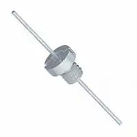
SFJE
(¼-28 UNF Thread : 9.8mm Round Head)
Not Recommended for New Designs – Refer to SFJG Range for Replacement
Circuit Configurations Available
Electrical Details
Electrical Configuration
Capacitance Measurement
Current Rating
Insulation Resistance (IR)
Temperature Rating
Ferrite Inductance (Typical)
See Circuit Configuration
@ 1000hr Point
15A
10G or 1000F
-55oC to +125oC
Not Applicable
Mechanical Details
Head Diameter
Nut A/F
Washer Diameter
Mounting Torque
9.8mm (0.386")
7.92mm (0.312")
11.35mm (0.447")
0.9Nm (7.97lbf in) max.
6.7mm O.D., 5.5mm A/F
(0.264" O.D., 0.217" A/F)
Mounting Hole Diameter
¼-28 UNF Class 2A Thread
Max. Panel Thickness
Weight (Typical)
Finish
2.3mm (0.091")
3.0g (0.11oz)
Silver plate on copper undercoat
C Configuration
1GHz
100pF
C0G
3kV#
3.6kV
4
22
SFJEC3K00151MC
150pF
C0G
3kV#
3.6kV
7
25
SFJEC3K00221MC
220pF
C0G
3kV#
3.6kV
10
29
SFJEC2K00331MC
330pF
C0G
2kV#
2.4kV
13
33
SFJEC2K00471MC
470pF
C0G
2kV#
2.4kV
1
16
35
SFJEC2K00681MC
680pF
C0G
2kV#
2.4kV
2
19
39
SFJEC2K00102MC
1.0nF
C0G
2kV#
2.4kV
4
23
41
SFJEC2K00152MX
1.5nF
X7R
2kV#
2.4kV
7
26
45
2.2nF
X7R
2kV#
2.4kV
10
30
50
3.3nF
X7R
2kV#
2.4kV
13
33
52
4.7nF
X7R
2kV#
2.4kV
1
16
36
55
6.8nF
X7R
2kV#
2.4kV
2
19
39
57
10nF
X7R
2kV#
2.4kV
4
22
41
60
15nF
X7R
1kV#
1.2kV
7
25
44
62
22nF
X7R
1kV#
1.2kV
10
29
46
65
33nF
X7R
1kV#
1.2kV
13
33
48
68
47nF
X7R
1kV#
1.2kV
1
16
35
50
70
SFJEC2K00222MX
SFJEC2K00332MX
SFJEC2K00682MX
SFJEC2K00103MX
SFJEC1K00153MX
SFJEC1K00223MX
SFJEC1K00333MX
SFJEC1K00473MX
0 = No hardware supplied
SFJEC2K00472MX
SFJEC1K00683MX
10MHz
SFJEC3K00101MC
1MHz
DWV
(dc)
0.1MHz
Rated
Voltage
(dc)
Other options available – please contact factory
Dielectric
Product Code
1 = supplied with standard nut and wavy washer
Capacitance
20%
100MHz
Hardware
(Nuts &
Washers
etc.)
Typical Insertion Loss (db)
0.01MHz
Ferrite Inductance (Typical) - 50nH
68nF
X7R
1kV#
1.2kV
2
19
39
54
>70
100nF
X7R
500#
750
4
22
41
57
>70
150nF
X7R
500#
750
7
25
45
60
>70
SFJEC5000224MX
220nF
X7R
500#
750
10
29
49
62
>70
SFJEC5000334MX
330nF
X7R
500#
750
13
33
52
66
>70
SFJEC5000474MX
470nF
X7R
500
750
1
16
35
55
68
>70
SFJEC3000684MX
680nF
X7R
300
600
2
19
38
58
70
>70
SFJEC2000105MX
1.0F
X7R
200
500
4
22
41
61
>70
>70
SFJEC1000155MX
1.5F
X7R
100
250
7
25
45
64
>70
>70
SFJEC1000225MX
2.2F
X7R
100
250
10
29
48
66
>70
>70
SFJEC0500335MX
3.3F
X7R
50
125
14
34
52
70
>70
>70
SFJEC5000104MX
SFJEC5000154MX
# - Also rated for operation at 115Vac 400Hz. Self-heating will occur – evaluation in situ recommended
Syfer Technology Ltd.
Old Stoke Road, Arminghall
Norwich, Norfolk, NR14 8SQ
United Kingdom
Tel: +44 1603 723300 | Email sales@syfer.co.uk | www.syfer.com
SFJE Issue 2 (P108893) Release Date 04/03/14
Page 1 of 4
�L-C Configuration
0.1MHz
100MHz
Typical Insertion Loss (db)
0.01MHz
Ferrite Inductance (Typical) - 50nH
Rated
Voltage
(dc)
DWV
(dc)
SFJEL3K00101MC
100pF
C0G
3kV#
3.6kV
7
24
SFJEL3K00151MC
150pF
C0G
3kV#
3.6kV
10
27
SFJEL3K00221MC
220pF
C0G
3kV#
3.6kV
12
30
SFJEL2K00331MC
330pF
C0G
2kV#
2.4kV
1
16
34
SFJEL2K00471MC
470pF
C0G
2kV#
2.4kV
2
19
38
SFJEL2K00681MC
680pF
C0G
2kV#
2.4kV
3
22
41
SFJEL2K00102MC
1.0nF
C0G
2kV#
2.4kV
6
25
44
SFJEL2K00152MX
1.5nF
X7R
2kV#
2.4kV
9
29
48
SFJEL2K00222MX
2.2nF
X7R
2kV#
2.4kV
12
31
51
3.3nF
X7R
2kV#
2.4kV
15
35
54
4.7nF
X7R
2kV#
2.4kV
1
18
39
57
6.8nF
X7R
2kV#
2.4kV
2
21
41
60
10nF
X7R
2kV#
2.4kV
4
23
43
63
15nF
X7R
1kV#
1.2kV
7
27
46
66
22nF
X7R
1kV#
1.2kV
10
30
48
68
33nF
X7R
1kV#
1.2kV
13
34
50
70
47nF
X7R
1kV#
1.2kV
1
17
37
51
>70
68nF
X7R
1kV#
1.2kV
2
20
40
55
>70
100nF
X7R
500#
750
4
22
44
60
>70
150nF
X7R
500#
750
7
25
47
62
>70
SFJEL5000224MX
220nF
X7R
500#
750
10
29
49
66
>70
SFJEL5000334MX
330nF
X7R
500#
750
13
33
53
68
>70
SFJEL5000474MX
470nF
X7R
500
750
1
16
35
56
70
>70
SFJEL3000684MX
680nF
X7R
300
600
2
19
38
58
>70
>70
SFJEL2000105MX
1.0F
X7R
200
500
4
22
41
61
>70
>70
SFJEL1000155MX
1.5F
X7R
100
250
7
25
45
64
>70
>70
SFJEL1000225MX
2.2F
X7R
100
250
10
29
48
66
>70
>70
SFJEL0500335MX
3.3F
X7R
50
125
14
34
52
70
>70
>70
SFJEL2K00103MX
SFJEL1K00153MX
SFJEL1K00223MX
SFJEL1K00333MX
SFJEL1K00473MX
SFJEL1K00683MX
SFJEL5000104MX
SFJEL5000154MX
Other options available – please contact factory
SFJEL2K00682MX
0 = No hardware supplied
SFJEL2K00472MX
1 = supplied with standard nut and wavy washer
SFJEL2K00332MX
1MHz
1GHz
Dielectric
Hardware
10MHz
Capacitance
20%
Product Code
# - Also rated for operation at 115Vac 400Hz. Self-heating will occur – evaluation in situ recommended
Ordering Information
Type
Case Style
Thread
Electrical
configuration
SF
J
E
C
Syfer Filter
7.92mm A/F
¼-28
UNF
C = C Filter
L = L-C Filter
Voltage
(dc)
Capacitance in
picofarads (pF)
500
Capacitance Tolerance
0102
M
M = 20%
300 = 300V
First digit is 0. Second and
third digits are significant
figures of capacitance code.
The fourth digit is the number
of zeros following.
500 = 500V
Examples: 0101 = 100pF
050 = 50V
100 = 100V
200 = 200V
1K0 = 1kV
2K0 = 2kV
Dielectric
Hardware
X
0
C = C0G/NP0
0 = Without
X = X7R
1 = With
0332 = 3300pF
3K0 =3kV
Note: The addition of a 4-digit numerical suffix code can be used to denote changes to the standard part.
Options include for example: change of pin length / custom body dimensions or threads / alternative voltage rating / non-standard intermediate capacitance values / test
requirements.
Please refer specific requests to the factory.
Syfer Technology Ltd.
SFJE Issue 2 (P108893) Release Date 04/03/14
Page 2 of 4
�Surface Mount and Panel Mount Solder-in filters
Solder pad layouts are included with the detailed information
for each part.
Recommended soldering profile
E01, E03, E07 SBSP ranges are compatible with all standard
solder types including lead-free, maximum temperature
260°C. For SBSG, SBSM and SFSS ranges, solder time should
be minimised, and the temperature controlled to a maximum
of 220°C. For SFSR, SFST and SFSU ranges the maximum
temperature is 250°C.
Cooling to ambient temperature should be allowed to occur
naturally. Natural cooling allows a gradual relaxation of
thermal mismatch stresses in the solder joints. Draughts
should be avoided. Forced air cooling can induce thermal
breakage, and cleaning with cold fluids immediately after a
soldering process may result in cracked filters.
Note: The use of FlexiCap™ terminations is strongly
recommended to reduce the risk of mechanical cracking.
Soldering to axial wire leads
Soldering temperature
The tip temperature of the iron should not exceed 300°C.
Dwell time
Soldering of filters
The soldering process should be controlled such that the filter
does not experience any thermal shocks which may induce
thermal cracks in the ceramic dielectric.
The pre-heat temperature rise of the filter should be kept to
around 2°C per second. In practice successful temperature
rises tend to be in the region of 1.5°C to 4°C per second
dependent upon substrate and components.
The introduction of a soak after pre-heat can be useful as it
allows temperature uniformity to be established across the
substrate thus preventing substrate warping. The magnitude
or direction of any warping may change on cooling imposing
damaging stresses upon the filter.
Dwell time should be 3-5 seconds maximum to minimise the
risk of cracking the capacitor due to thermal shock.
Heat sink
Where possible, a heat sink should be used between the solder
joint and the body, especially if longer dwell times are
required.
Bending or cropping of wire leads
Bending or cropping of the filter terminations should not be
carried out within 4mm (0.157”) of the epoxy encapsulation,
the wire should be supported when cropping.
Soldering irons should not be used for mounting surface
mount filters as they can result in thermal shock
damage to the chip capacitor.
A more comprehensive application note covering
installation of all Syfer products is available on the Syfer
website.
Syfer Technology Ltd.
Old Stoke Road, Arminghall
Norwich, Norfolk, NR14 8SQ
United Kingdom
Tel: +44 1603 723300 | Email sales@syfer.co.uk | www.syfer.com
SFJE Issue 2 (P108893) Release Date 04/03/14
Page 3 of 4
�Resin filled screw mounted EMI filters
Grounding
General
To ensure the proper operation of the filters, the filter body
should be adequately grounded to the panel to allow an
effective path for the interference. The use of locking
adhesives is not recommended, but if used should be applied
after the filter has been fitted.
The ceramic capacitor, which is the heart of the filter, can be
damaged by thermal and mechanical shock, as well as by
over-voltage. Care should be taken to minimise the risk of
stress when mounting the filter to a panel and when soldering
wire to the filter terminations.
Mounting to chassis
Mounting torque
It is important to mount the filter to the bulkhead or panel
using the recommended mounting torque, otherwise damage
may be caused to the capacitor due to distortion of the case.
When a threaded hole is to be utilised, the maximum mounting
torque should be 50% of the specified figure which relates to
unthreaded holes. For details of torque figures for each filter
range, please see below.
Torque (max.)
Thread
Minimum plate thickness
Users should be aware that the majority of these filters have
an undercut between the thread and the mounting flange of
the body, equal to 1.5 x the pitch of the thread. Mounting into
a panel thinner than this undercut length may result in
problems with thread mating and filter position. It is
recommended that a panel thicker than this undercut length be
used wherever possible.
Maximum plate thickness
This is specified for each filter in order that the nut can be fully
engaged even when using a washer.
Soldering to axial wire leads
With nut
Into tapped hole
-
0.15Nm (1.32lbf in)
The tip temperature of the iron should not exceed 300°C.
0.25Nm (2.21lbf in)
0.15Nm (1.32lbf in)
Dwell time
0.3Nm (2.65lbf in)
0.15Nm (1.32lbf in)
Dwell time should be 3-5 seconds maximum to minimise the
risk of cracking the capacitor due to thermal shock.
0.35Nm (3.09lbf in)
0.18Nm (1.59lbf in)
Heat sink
M4 & 8-32 UNC
0.5Nm (4.42lbf in)
0.25Nm (2.21lbf in)
M5, 12-32 UNEF & 2BA
0.6Nm (5.31lbf in)
0.3Nm (2.65lbf in)
Where possible, a heat sink should be used between the solder
joint and the body, especially if longer dwell times are
required.
M6 & 1/4-28 UNF
0.9Nm (7.97lbf in)
-
M2.5 & 4-40 UNC
M3
6-32 UNC
M3.5
Tools
Hexagonal devices should be assembled using a suitable
socket. Round bodied filters may be fitted to the panel in one
of two ways (and should not be fitted using pliers or other
similar tools which may damage them):
Round bodies with slotted tops are designed to be screwed
in using a simple purpose-designed tool.
Round bodies without slotted tops are intended to be
inserted into slotted holes and retained with a nut.
Syfer Technology Ltd.
Old Stoke Road, Arminghall
Norwich, Norfolk, NR14 8SQ
United Kingdom
Tel: +44 1603 723300 | Email sales@syfer.co.uk | www.syfer.com
Soldering temperature
Bending or cropping of wire leads
Bending or cropping of the filter terminations should not be
carried out within 4mm (0.157”) of the epoxy encapsulation,
the wire should be supported when cropping.
RoHS compliance
All surface mount filters, resin sealed panel mount filters and
power filters are fully RoHS compliant through material
exemption, although care must be taken not to exceed the
maximum soldering temperatures of surface mount parts.
Standard hermetic sealed panel mount filters use SnPb solders
as part of their assembly, and are intended for exempt
applications such as aerospace or military. Substitution of the
SnPb solder with Pb free solders is possible to create a RoHS
compliant part – please contact factory for further details.
SFJE Issue 2 (P108893) Release Date 04/03/14
Page 4 of 4
�
很抱歉,暂时无法提供与“SFJEC1K00153MX1”相匹配的价格&库存,您可以联系我们找货
免费人工找货