EU
RoHS
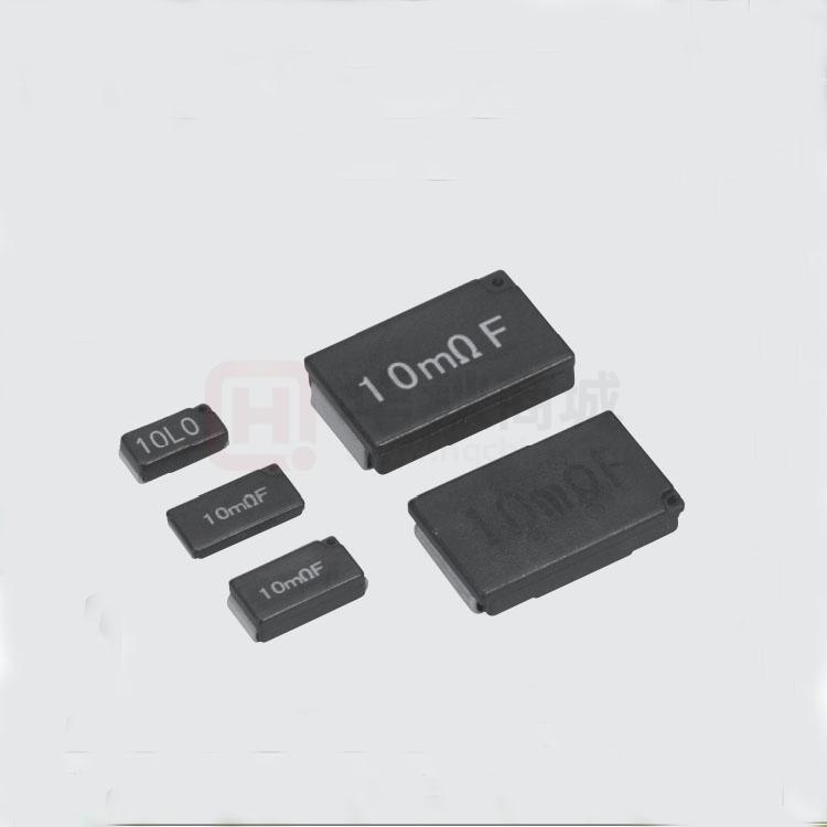
CURRENT SENSING
TSL·SL(金属元件型)·SLN
电流检测用片式电阻器
Current Detecting Chip Resistors
Construction
■ 结构图
电流检测电阻器
Current Detecting Chip Resistors
L
W
b
t
a
①
c
②
①
②
③
外观颜色:黑色
型号 Type
(Inch Size Code)
z 是小型、超低电阻值(3mΩ~)、高精度(±0.5%)、SMD形
状的电流检测用电阻器。
z 是阻燃性树脂(UL94 V-0)模压密封型。
z 由于是模压成形,尺寸精度高,装载性、耐冲击性好。
z 由于是金属端子电极,端子强度、焊接性优异。
z 是金属板端子电极结构,吸收热膨胀收缩。
z 对应波峰焊、回流焊、烙铁焊接。
z 端子无铅品,符合欧盟RoHS。
z AEC-Q200相关数据已取得。
z SMD type of small size, ultra-low resistance (3mΩ~) and high
accuracy (±0.5%) resistor for current detection.
z Encapsulated with flame retardant resin molding. (UL94 V-0)
z Excellent dimension accuracy, mountability and shock-resistance due
to molded products.
z Excellent terminal strength and solderability due to structure of a
metal plate terminal electrode.
z Easy to absorb the thermal expansion and shrinkage because of a
metal plate terminal structure.
z Suitable for flow, reflow and iron solderings.
z Products with lead free termination meet EU-RoHS requirements.
z AEC-Q200 qualified.
■ 用途 Applications
Automotive
Note PCs
Battery packs
AC Adapters
DC-DC converters, etc.
汽车
笔记本电脑
电池组
AC适配器
DC-DC换流器
SL07(2010)
TSL1(2512)
SL1 • SLZ1(2512)
SL2(4527)
SLN2(4527)
W±0.2
2.5
3.1
3.1
7.0
7.0
尺寸 Dimensions(mm)
t±0.2
a±0.2
b±0.2
1.7
2.0
0.9
1.0
2.4
0.7
1.9
2.4
1.2
2.5
5.0
1.7
2.4
5.5
1.6
Weight(g)
(1000pcs)
c
1.2±0.3
45
1.2±0.3
41
1.2±0.3
90
2.6±0.5
476
2.55±0.4
500
■ 品名构成 Type Designation
Example
实例
SL
1
T
TE
10L0
F
75
൰፯
Product
Code
߇࢙ށఋ
Power
Rating
ޤᏊװಅإ፣
Terminal
Surface Material
ߗ۫ৠ
Taping
࢞ݢڅᏟፎə
Nominal
Resistance
Ꮯፎኧᅒُ
Resistance
Tolerance
ݢᏟၫޡႼ༮
TSL
SL
SLN
0.7: 0.75W
1 : 1W
2 : 2W
T : Sn
TE : Plastic
embossed
BK: Bulk
D,F : 4 digits
J ,G : 3 digits
D :±0.5%
F : ±1%
G : ±2%
J : ±5%
※1
电阻值范围(Ω)
Resistance Value
3m~9.1m
10m~91m
0.1~0.36
3位显示
3 digits
3L0~9L1
10L~91L
R10~R36
Ex.
0.1Ϯ:R10
5mϮ:5L0
电阻值范围(Ω)
Resistance Value
5m~9.1m
10m~91m
0.1~0.36
T.C.R
˄×10ˉ6/K˅
Nil˖0ȋ150
0ȋ200
±75˄SLN2˅
±100
±110
±180
50˖±50˄SL1˅
75˖±75˄SL1˅
4位显示
4 digits
5L00~9L10
10L0~91L0
R100~R360
■跳线额定 Jumper Ratings
IEC 60115-1
JIS C 5201-1
型 号
Type
SLZ1
■ 额定值
L±0.3
5.0
6.3
6.3
11.5
11.5
端子表面材质,以无铅品为准。
欲知关于此产品含有的环境负荷物质详情(除EU-RoHS以外),请与我们联系。
编带细节请参考卷末附录C。
The terminal surface material lead free is standard.
Contact us when you have control request for environmental hazardous material other than the substance specified by EU-RoHS.
For further information on taping, please refer to APPENDIX C on the back pages.
Reference Standards
■ 参考标准
Molded resin
Resistive element (Metal plate)
Electrode
■ 外形尺寸 Dimensions
Coating color:Black
Features
■ 特点
③
模压树脂
电阻体(金属元件)
电极
电阻值
Resistance
0.5mΩ以下
0.5mΩ max.
额定电流
Current Rating
44A
电阻温度系数
T.C.R.(×10-6/K)
4000以下
4000 max.
Ratings
型 号
Type
额定功率
Power
Rating
SL07
0.75W
TSL1
1W
SL1
1W
SL1(TCR±50ppm)
SL1(TCR±75ppm)
1W
1W
SL2
2W
SLN2
2W
额定环境温度
Rated Ambient
Temp.
70℃
额定端子部温度
Rated Terminal
Part Temp.
125℃
120℃
D:±0.5%
E24・E96※4
电阻值范围※3
Resistance Range(Ω)
F:±1%
G:±2%
E24・E96※4
E24
-
5m~100m
10m~100m
5m~100m
-
10m~102m
5m~102m
3m、4m
-
34.8m~200mΩ 34.8m~200mΩ
20m~200mΩ 20m~200mΩ
-
-
10m~360mΩ 5m~360mΩ
3m、4m
5m~200m
5m~200m
-
J:±5%
E24
电阻温度系数
T.C.R.
(×10-6/K)
编带和包装数/卷
Taping & Q'ty /Reel (pcs)
使用温度范围
Operating Temp. Range
TE
0~200:R<11mΩ
0~150:R ≥ 11mΩ
±180:R<15mΩ
5m~100m
±100:R ≥ 15mΩ
±180:R<15mΩ
5m~100m
±100:R ≥ 15mΩ
-55℃~+180℃
±50ppm
36m~200mΩ
±75ppm
20m~200mΩ
±180:R<11mΩ
3m~360mΩ ±100:R
≥ 11mΩ
±110:R<10mΩ
5m~200m
±75:R ≤ 10mΩ
5m~100m
2,000
3,000
1,000
额定电压是√额定功率×公称电阻值所算出的值或表中最高使用电压两者中小的值为额定电压。
Rated voltage = √ Power Rating×Resistance value or Max. working voltage, whichever is lower.
※3 在电阻值范围内,3m、4m、5m、6m、7m、8m、9mΩ都对应。 3m, 4m, 5m, 6m, 7m, 8m and 9mΩ are available in each resistance range.
※4 SL07及SL1(T.C.R:±50/±75 ppm中102mΩ≤R≤200mΩ)的E96系列不适用(仅E24系列) SL07 and SL1 (T.C.R: ±50/±75 ppm, 102mΩ≤R≤200mΩ) offer only E24 series.
根据客户的使用状况,如果不清楚是该使用额定环境温度还是额定端子部温度,请以额定端子部温度为优先。
详情请参照14~17页的“端子部温度负荷特性曲线的说明”。
If any questions arise whether to use the“Rated Ambient Temperature”or the“Rated Terminal Part Temperature”in your usage conditions, please give priority to the“Rated Terminal Part Temperature”.
For more details, please refer to“Introduction of the derating curves based on the terminal part temperature”in page 14 to 17.
本产品目录中记载的产品规格如有变更,恕不一一奉告。订购以及使用之前,请仔细确认规格表的内容。
用于车载设备、医疗设备、航空设备以及其它涉及人身安全、或可能引起重大损失的设备上时,请务必事先与我公司联系。这些产品在这类用途中出现故障或失灵可能导致人身事故或严重损坏。
Specifications given herein may be changed at any time without prior notice. Please confirm technical specifications before you order and/or use.
Contact our sales representatives before you use our products for applications including automotives, medical equipment and aerospace equipment.
Malfunction or failure of the products in such applications may cause loss of human life or serious damage.
Nov. 2017
www.koaglobal.com
�Derating Curve
80
额定功率比(%)
80
60
40
20
Percent rated power
100
Percent rated power
100
SLN2
60
SL07,TSL,SL1, SL2
40
20
0
-60 -40 -20 0 20 40 60 80 100 120 140 160 180
-55
70
环境温度 Ambient temperature(℃)
0
-60 -40 -20 0 20 40 60 80 100 120 140 160 180
-55
125
端子部温度 Terminal part temperature(℃)
在环境温度70℃以上使用时,应按照上图负荷减轻特性曲线,减小额定功率。
For resistors operated at an ambient temperature of 70℃ or above, a
power rating shall be derated in accordance with the above derating curve.
超过上述端子部温度使用时,请根据负荷减轻特性曲线减小额定功率后使用。
※ 关于使用方法,请参照卷首的“端子部温度负荷减轻特性曲线的说明”。
For resistors operated terminal part temperature of described for each size
or above a power rating shall be derated in accordance with derating curve.
※Please refer to“Introduction of the derating curve based on the terminal
part temperature”on the beginning of our catalog before use.
■ 温度上升 Temperature Rise
温度上升(℃)
Temperature rise
150
150
125
100
②
①
75
50
※ 33mΩ
10mm pattern
25
0
0
25
50
75
额定功率比 Power rating(%)
100
100
150
②
①
75
SL07 ②
SL07 ①
175
125
125
100
②
75
①
50
50
※ TSL1:20mΩ
SLN2:110mΩ
10mm pattern
25
0
SL07
200
SLN2 ②
TSL1 ②
SLN2 ①
TSL1 ①
175
温度上升(℃)
Temperature rise
175
TSL1/SLN2
200
SL2 ②
SL1 ②
SL2 ①
SL1 ①
温度上升(℃)
Temperature rise
SL1/SL2
200
电流检测电阻器
Current Detecting Chip Resistors
额定功率比(%)
■ 负荷减轻特性曲线
0
25
50
75
额定功率比 Power rating(%)
100
25
0
※ 20mΩ
10mm pattern
0
25
50
75
额定功率比 Power rating(%)
100
表面温度上升,是以本公司测定条件测定的,由于使用状况、使用基板不同,数值也会有所不同,因此,在使用时请另行询问。
Regarding the temperature rise, the value of the temperature varies per conditions and board for use since the temperature is measured under our measuring conditions.
Please refer to us before use.
■ 性能
Performance
电阻值
Resistance
电阻温度系数
T.C.R.
标准值 Performance Requirements
ΔR±%
代表值
保证值 Limit
在规定的允许偏差内
–
Within specified tolerance
在规定值以内
–
Within specified T.C.R.
过载(短时间)
Overload(Short time)
1:SL07, TSL1, SL1, SL2
0.5:SLN2
1:SL07, TSL1, SL1, SL2
0.25:SLN2
耐焊接热
Resistance to soldering heat
1:SL07, TSL1, SL1, SL2
0.5:SLN2
1:SL07, TSL1, SL1, SL2
0.5:SLN2
1:SL07, TSL1, SL1, SL2
0.5:SLN2
0.5:SL07, TSL1, SL1, SL2
0.25:SLN2
2:SL07, TSL1, SL1, SL2
0.5:SL07, TSL1, SL1, SL2
0.5:SLN2
0.25:SLN2
2:SL07, TSL1, SL1, SL2
1:SLN2
1
0.5
0.25
试验项目
Test Items
温度突变
Rapid change of temperature
耐湿负荷
Moisture resistance
在70℃时的耐久性
Endurance at 70℃
低温放置
Low temperature exposure
■ 使用注意事项
Typical
试验方法
Test Methods
25℃
25℃/+125℃
SL07:额定功率×4倍施加5秒钟 Rated power×4 for 5s
TSL1:额定功率×2.5倍施加5秒钟 Rated power×2.5 for 5s
SL1,SL2:额定功率×5倍施加5秒钟 Rated power×5 for 5s
SL1(T.C.R:±50/±75):额定功率×4倍施加5秒钟
SL1(T.C.R:±50/±75):Rated power×4 for 5s
260℃±5℃, 10s±1s
260℃±5℃, 10s~12s
-55℃(30min.)/+150℃(30min.)100 cycles
-55℃(15min.)/+150℃(15min.)1000 cycles
40℃±2℃, 90%~95%RH, 1000h
1.5小时ON、0.5小时OFF的周期 1.5h ON/0.5h OFF cycle
85℃±2℃, 85%RH±3%RH, 1000h
额定功率×0.1倍 Rated power×0.1
70℃±2℃, 1000h
1.5小时ON、0.5小时OFF的周期 1.5h ON/0.5h OFF cycle
SL07, TSL1, SL1, SL2:-55℃, 1h
SLN2:-65℃, 24h
( )
Precautions for Use
z 作为分流电阻使用时,应考虑和周围线圈的电磁感应后配置模式。
z 在50 mΩ以下的电阻值,根据焊盘图案大小和接续焊接的量,焊接后的电阻值会变动。应在事前确认电阻值降低•提高的影响后,进行设备设计。
z In case of using the low ohm resistors as shunt resistors, please lay out a pattern considering the electromagnetic induction with surrounding inductors.
z In the resistance values of 50mΩor under, the resistance value after soldering may change depending on the size of pad pattern or solder amount. Make sure
the effect of decline/increase of resistance value before designing.
本产品目录中记载的产品规格如有变更,恕不一一奉告。订购以及使用之前,请仔细确认规格表的内容。
用于车载设备、医疗设备、航空设备以及其它涉及人身安全、或可能引起重大损失的设备上时,请务必事先与我公司联系。这些产品在这类用途中出现故障或失灵可能导致人身事故或严重损坏。
Specifications given herein may be changed at any time without prior notice. Please confirm technical specifications before you order and/or use.
Contact our sales representatives before you use our products for applications including automotives, medical equipment and aerospace equipment.
Malfunction or failure of the products in such applications may cause loss of human life or serious damage.
Nov. 2017
www.koaglobal.com
�