物料型号:WG73系列
器件简介:
- 脉冲耐受电压优于WK73系列
- 适用于波峰焊和回流焊
- 符合欧盟RoHS要求
- 经过AEC-Q200测试
引脚分配:文档中未明确列出引脚分配,但提到了端子部分的尺寸和构造。
参数特性:
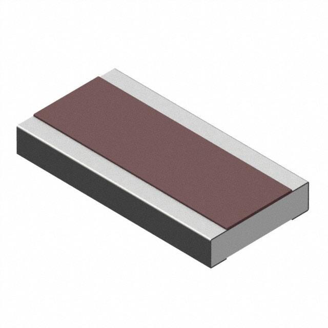
- 尺寸和构造:包括陶瓷基板、锡镀层、镍镀层、保护性电阻内电极膜涂层
- 型号(英寸尺寸代码)和尺寸(英寸/毫米)
- 额定功率:2B型号1W,2H型号1.5W,3A型号2W
- 电阻公差:K(±10%),M(±20%)
- 表面材料和端子:TD为4mm间距冲压纸,TE为4mm间距压花塑料
功能详解:
- 电阻器在70°C或更高环境温度下工作时,需要根据退率曲线进行功率退率
- 端子部分温度超过规定尺寸或以上时,也需要根据退率曲线进行功率退率
应用信息:
- 应用在脉冲功率电阻器领域,具有防浪涌特性
- 环境应用包括温度升高和单脉冲限制电能
封装信息:
- 提供了不同尺寸的封装信息,包括2B(0612)、2H(1020)、3A(1225)
性能特性:
- 包括电阻、温度系数(T.C.R.)、过载(短时间)、耐焊热性、弯曲测试、温度快速变化、湿度抵抗力、70°C耐久性、高温暴露等参数和测试方法。
订购信息:
- 提供了型号、标称电阻、电阻公差、功率等级、表面材料、端子和包装等订购信息。
注意事项:
- 规格可能会随时更改,建议在订购和/或使用前确认技术规格。