iCE40 Ultra Wearable Development Platform User Guide
EB100 Version 1.0, July 2015
�iCE40 Ultra Wearable Development Platform
Introduction
The iCE40 Ultra Wearable Development Platform is an easy-to-use platform which demonstrates how the iCE40 Ultra
and MachXO2 FPGAs can be utilized in wearable and mobile applications. Along with the evaluation board and accessories, there are reference designs available to demonstrate the functionality of the boards and components.
The iCE40 Ultra Wearable Development Platform consists of two boards: the Main Board and the Sensor Board. The
Main Board contains the iCE40 Ultra and MachXO2 FPGAs, which drive various components on the board. The iCE40
Ultra focuses on interfacing with peripheral components such as LEDs, sensors and BLE connectivity. The MachXO2
focuses on driving the MIPI DSI Display from a Quad SPI flash functioning as a frame buffer and storage device. The
Sensor Board contains several sensors that are typically found in mobile and wearable devices. By separating the two
boards, the interconnect headers can be used to directly interface with peripherals for testing (see the Headers section).
The contents of this user guide include a description of the board features, header connection descriptions and pinouts,
instructions on loading demonstration bitstreams, a complete set of schematics, and the bill of materials.
Features
The iCE40 Ultra Wearable Development Platform includes:
• iCE40 Ultra Wearable Development Platform Main Board:
— iCE40 Ultra (iCE5LP-4K-SWG36) device in a 36-ball WLCSP package
— MachXO2 (LCMXO2-2000ZE-1UWG49) device in a 49-ball WLCSP package
— High-current IR, White, and RGB LEDs
— Stereo Microphones
— Connector and driver circuitry for MIPI DSI Display
— Headers for I2C, SPI, and UART
— Mini-USB programming connection
— Battery charger
— RoHS-compliant packaging and process
• iCE40 Ultra Wearable Development Platform Sensor Board:
– Bluetooth Low-Energy Module
– Heart-rate/SpO2 Sensor and Analog Front End
– Skin temperature sensor
– Pressure sensor
– Accelerometer/Gyroscope
– Pads for soldering on battery (charger accepts Li-Ion and Li-Po)
• Syma 652030 Battery – 3.7 V, 250 mAh Lithium-Polymer Battery provides power while the USB cable is disconnected
• LG LH154Q01 Display – 240x240 Single Lane MIPI DSI Display. Must be attached prior to power-up
• USB Connector Cable – A mini-USB port provides power and a programming interface for the board
• Watch Strap – A watch strap comes pre-attached to the Sensor Board
Note: Static electricity can severely shorten the lifespan of electrical components. Use care while handling the
iCE40 Ultra Wearable Development Platform to avoid ESD damage.
2
�iCE40 Ultra Wearable Development Platform
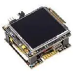
Figure 1 through Figure 4 show the top and bottom sides of the Main and Sensor boards, with key features highlighted.
Figure 1. Main Board (Top Side)
LED Select Jumper
FTDI Power Jumper
Reset Button
User LEDs (XO2)
Display Connector
MachXO2
MachXO2 Config LED
iCE5LP Config LED
RGB LED
iCE5LP
High-Brightness LED
IR LED
Microphone (L)
Battery Charger
Status LEDs
Figure 2. Main Board (Bottom Side)
Backlight Driver
Microphone (R)
FTDI Programming Chip
Power Switch
Battery Charger
Mini -USB Socket
3
�iCE40 Ultra Wearable Development Platform
Figure 3. Sensor Board (Top Side)
Pressure Sensor
Heart Rate/Oxygen Sensor
Analog Front End
Accelerometer/
Gyroscope
Bluetooth Low Energy Module
Figure 4. Sensor Board (Bottom Side)
Heart Rate/Oxygen Sensor
Skin Temperature Sensor
4
�iCE40 Ultra Wearable Development Platform
Lattice Semiconductor Devices
The Main Board features an iCE5LP4K and a MachXO2-2000ZE FPGA.
The iCE5LP4K has a 1.2 V core supply and is packaged in a 36-ball WLCSP package. For a complete description
of this device, see DS1048, iCE40 Ultra Family Data Sheet.
The MachXO2-2000ZE has a 1.2 V core supply and is packaged in a 49-ball WLCSP package. For a complete
description of this device, see DS1035, MachXO2 Family Data Sheet.
Software Requirements
The following software must be installed before designs can be developed for this board:
• iCEcube2 2014-12 (or higher)
• Diamond® 3.4 (or higher)
• Diamond Programmer 3.4 (or higher)
This software is available at the Lattice website Design Software & IP page.
Board Power
The iCE40 Ultra Wearable Development Platform uses the USB connection as its primary source of power. It is
also equipped with a battery and charger for use without a wired connection. A power switch (SW2) allows for the
regulators to be disabled while allowing the battery to continue charging. Two status LEDs allow the battery charger
to be monitored (see Table 12).
The battery charger and regulators are located on the Main Board. The battery attaches to the Sensor Board.
Power is transferred between the two boards using the Power Connector header. See Table 2 for connections.
The VREG_ADJ I/O supply net for the iCE5LP is adjustable, but is an internal, reserved feature. Changing this net
from 3.3 V (default) to 1.8 V will cause voltage-level mismatches that can permanently damage the iCE5LP.
To allow current measurements to be made for specific supplies, resistors with test points have been inserted into
the circuit. Refer to Table 1 to see which test points correspond to which supplies.
Table 1. Supply Current Test Points
TP+
TP-
Resistance
MachXO2 1.2 V
Supply
TP20
TP21
0.5 Ohms
MachXO2 3.3 V
TP18
TP19
0.5 Ohms
iCE5LP 1.2 V
TP20
TP33
0.5 Ohms
iCE5LP 3.3 V
TP18
TP32
0.5 Ohms
3.3 V Regulator
TP16
TP17
0.5 Ohms
Display 3 V
TP25
TP24
0.5 Ohms
Display 1.8 V
TP22
TP23
0.5 Ohms
5
�iCE40 Ultra Wearable Development Platform
Headers
Four headers are used to connect the Main Board and the Sensor Board. The signals and connections are shown
in the tables below:
Figure 5. Headers
BLE Connector
SPI Connector
I2C Connector
Power Connector
Power Connector (Main Board J7, Sensor Board J5): Power connection between the two boards
Table 2. Power Connector
Pin Number
Signal
Description
1
3V3
Regulated 3.3 V supply
2
BT_3V7
Unregulated ~3.7 V battery voltage
3
VREG_ADJ
Adjustable I/O Voltage (3.3 V default)
4
GND
Ground
I2C Connector (Main Board J5, Sensor Board): Interface for pressure sensor, temperature sensor, and accelerometer/gyroscope
Table 3. I2C Connector
Pin Number
Signal
iCE5LP Ball #
1
Sensor SCL
C1
2
Sensor SDA
E2
SPI Connector (Main Board J6, Sensor Board): Interface for the Analog Front-End of the Heart Beat/SpO2 sensor
Table 4. SPI Connector
Pin Number
Signal
iCE5LP Ball #
1
AFE SCLK
D6
2
AFE MISO
F6
3
AFE Ready
B5
4
AFE SS
D5
5
AFE MOSI
E6
6
GND
—
6
�iCE40 Ultra Wearable Development Platform
BLE Connector (Main Board J3, Sensor Board): Contains a UART connection to iCE5LP and a configuration SPI
connection for the iCE5LP
Table 5. BLE Connector
Pin Number
Signal
Ball #
1
BLE Prog
MachXO2 G2
2
BLE SS
Config
3
BLE MISO
Config
4
BLE MOSI
Config
5
BLE SCLK
Config
6
CRSTb
—
7
CDONE
MachXO2 E3
8
UART Rx (out)
iCE5LP F5
9
UART Tx (in)
iCE5LP E5
10
GND
—
Jumpers
The following jumpers can be used for adjusting board functionality:
• High-current LED select (J50): Controls whether the IR LED (1+2) or High-current White LED (2+3) is driven by
the iCE5LP device
• FTDI Power (J51): To minimize power consumption and increase battery life, the FTDI programming chip can
have its power supply cut-off by removing the jumper from J51. J51 must be in place prior to powering up in order
to program the devices on this board.
7
�iCE40 Ultra Wearable Development Platform
Test Points
Several test points have been included into the design to ease debug. Descriptions of these test points can be
found below:
Table 6. Main Board Test Points
Test Point
Signal/Function
1
Configuration Signal: CResetn_FTDI
2
Configuration Signal: iCE_CDONE
3
Configuration Signal: FTDI_TCK (XO2)
4
Configuration Signal: FTDI_TDI (XO2)
5
Configuration Signal: FTDI_TDO (XO2)
6
Configuration Signal: FTDI_TMS (XO2)
11
Configuration Signal: JTAGEN (XO2)
12
Configuration Signal: PROGRAMN (XO2)
13
Configuration Signal: INITN (XO2)
16
Current Measurement (See Table 1)
17
Current Measurement (See Table 1)
18
Current Measurement (See Table 1)
19
Current Measurement (See Table 1)
20
Current Measurement (See Table 1)
21
Current Measurement (See Table 1)
22
Current Measurement (See Table 1)
23
Current Measurement (See Table 1)
24
Current Measurement (See Table 1)
25
Current Measurement (See Table 1)
28
Configuration Signal: FLASH_MISO (iCE)
29
Configuration Signal: FLASH_MOSI (iCE)
30
Configuration Signal: FLASH_CSB (iCE)
31
Configuration Signal: FLASH_SCLK (iCE)
32
Current Measurement (See Table 1)
33
Current Measurement (See Table 1)
34
3.3 V Regulator Output Control (See TPS7A7200)
35
3.3 V Regulator Output Control (See TPS7A7200)
36
3.3 V Regulator Output Control (See TPS7A7200)
8
�iCE40 Ultra Wearable Development Platform
Table 7. Sensor Board Testpoints
Test Point
Signal/Function
1
AFE4403: CLKOUT
2
BLE Config: SWCLK
3
LPS25H: INT1
4
AFE4403: TX3
5
AFE4403: INN
6
AFE4403: INP
7
AFE4403: ADC_RDY
8
AFE4403: LED_DRV_SUP
9
AFE4403: VCM
10
AFE4403: TXP
11
AFE4403: TXN
12
Battery Connector (+)
13
Battery Connector (-)
14
LSM330DLC: INT1_G
15
LSM330DLC: INT2_G
16
BLE Config: SWDIO
17
AFE4403: Manual Reset, short to TP18
18
AFE4403: Manual Reset, short to TP17
Device Interconnects
Six general purpose connections have been made between Lattice MachXO2 and iCE5LP devices for communication between FPGAs. Level translators have been implemented on these lines, which limit their operation frequency. Table 8 lists connection ports and maximum operation frequencies:
Table 8. MachXO2 and iCE5LP Interconnections
Net Number
MachXO2 Ball
iCE5LP Ball
Max Frequency
1
E6
C2
20 MHz
2
E5
B1
20 MHz
3
D5
D2
100 MHz
4
D4
B2
100 MHz
5
G4
B4
100 MHz
6
F4
F4
100 MHz
9
�iCE40 Ultra Wearable Development Platform
Display
The iCE40 Ultra Wearable Development Platform includes an LG LH154Q01 Display and necessary driving circuitry. MIPI DSI clock and data signals are driven by the Lattice MachXO2 device, through a resistor network for
achieving proper voltage levels. This display also provides a frame-sync signal, B_Sync, which is routed to a
MachXO2 pin. Display supplies and the backlight driver are controlled by outputs from the MachXO2.
Table 9. Display Signals
Signal
MachXO2 Ball
Clock HS+
C4
I/O Type
LVDS25
Clock HS-
D3 (Auto)
LVDS25 (Auto)
Clock LP+
C7
LVCMOS12
Clock LP-
C6
LVCMOS12
Data HS+
C1
LVDS25
LVDS25 (Auto)
Data HS-
D2 (Auto)
Data LP+
A7
LVCMOS12
Data LP-
B6
LVCMOS12
Reset
B2
LVCMOS33
B_Sync
A3
LVCMOS33
Backlight PWM
C3
LVCMOS33
3 V Enable
C2
LVCMOS33
1.8 V Enable
E2
LVCMOS33
Note: For the high-speed differential signals (Clock HS, Data HS) only the positive channel must be assigned, the
negative channel will be automatically placed.
Clock Sources
The Main Board has a single 27 MHz clock source that connects to the Lattice MachXO2 device. To use this external clock with the iCE5LP device, the 27 MHz clock can be routed from the MachXO2 via one of the six general
purpose interconnects. These connections can be found in Table 8.
Table 10. Clock Sources
Source
Frequency
XO2 Ball
iCE Ball
Oscillator
27 MHz
E4
—
Reset Button
A button (SW1) is included for performing resets of systems on board the iCE40 Ultra Wearable Development Platform. By default, this button will perform a configuration reset of the iCE5LP, MachXO2, and the Bluetooth module.
Table 11. Reset Resistors and Pins
Device
Resistor
FPGA Ball
MachXO2
R110
B3
iCE5LP
R62
Seeed BLE
R63
—
—
Note: If VREG_ADJ (see the Board Power section) is changed, these resistors must be removed to prevent voltage
level mismatches.
10
�iCE40 Ultra Wearable Development Platform
LEDs
The Main Board has four system status LEDs, two user LEDs, an RGB LED, an IR LED, and a High-current White
LED.
The iCE40 Ultra has I/O ports specially built for sinking current from high-power LEDs. The RGB LED ports (A6,
B6, and C6) are able to sink 24 mA each, while the high-current LED port (A2) is able to sink up to 500 mA.
Please note that the IR LED is only rated for 100 mA and can be damaged by incorrectly configuring the port in
custom designs. This is not a problem for the RGB LED and High-current White LED, since they are rated for more
current than the ports can sink.
The LED functions and FPGA connections are detailed below:
Table 12. Main Board LEDs
LED Number
MachXO2 Ball
iCE40 Ball
D1
D2
—
—
D3
Config
D4
E7
D5
F7
—
—
—
—
—
D8
—
—
—
—
—
—
D9 (R)
D9 (G)
D9 (B)
D10
D11
Function
Power Source Connected
Battery Charging
MachXO2 CDONE
User LED
User LED
Config
iCE40 CDONE
C6
RGB LED (Red)
B6
RGB LED (Green)
A6
RGB LED (Blue)
A2*
IR LED (see the Jumpers section)
A2*
High-current White LED (see the Jumpers section)
Sensors and Peripherals
The iCE40 Ultra Wearable Development Platform utilizes several third-party devices. Links for more information
can be found below:
Table 13. Main Board Sensors and Peripherals
Name
Microphone
Reference
Number
Interface
U6, U7
I2S
FPGA
Connections
iCE5LP: Clock (F3),
Data (E3)
11
Part Number
Link
MP34DB01
http://www.st.com/web/
en/catalog/sense_power/
FM125/SC1564/
PF250941
�iCE40 Ultra Wearable Development Platform
Table 14. Sensor Board Sensors and Peripherals
Reference
Number
Interface
FPGA
Connections
Part Number
Temperature
Sensor
U7
I2C
See Table 3
TMP112
http://www.ti.com/product/tmp112
Pressure Sensor
U3
I2C
See Table 3
LPS25H
http://www.st.com/web/
catalog/sense_power/
FM89/SC1316/PF255230
Accelerometer/
Gyroscope
U4
I2C
See Table 3
LSM330DLC
http://www.st.com/web/
en/catalog/sense_power/
FM89/SC1448/PF252427
Heart Rate &
Oxygen Sensor
U6
—
—
SFH7050
http://www.osramos.com/osram_os/en/
products/product-promotions/infrared-products/
sensor-family/biomonsensor-sfh-7050/index.jsp
Analog Front
End
U2
SPI
See Table 4
AFE4403
http://www.ti.com/product/afe4403
BLE Module
U5
UART
See Table 5
Seeed
113050012
http://www.seeedstudio.com/wiki/BLE_Micro
Name
Link
Flash Memory Devices
The Lattice MachXO2 and iCE5LP are each equipped with an external SPI Flash memory device.
Table 15. Flash Devices
Master Device
Reference Number
Part Number
MachXO2
U5
Micron N25Q032A13ESC40G
iCE5LP
U10
Micron M25P80-VMN6TP
The iCE5LP external Flash memory is intended for holding configuration data, while the MachXO2 external Flash
memory is intended for storing data, such as images for the included display. Because of the target application, the
Flash device connected to the MachXO2 is capable of using the higher-bandwidth Quad-SPI protocol.
Table 16. Flash Connections
Master Device
Reference Number
Signal
FPGA Ball
MachXO2
U5
DQ0
G1
DQ1
F5
DQ2
F3
iCE5LP
U10
12
DQ3
G3
SCLK
F6
CS
G7
MISO
F2
MOSI
D1
SCLK
E1
CS
F1
�iCE40 Ultra Wearable Development Platform
Board Configuration and Programming
Lattice MachXO2
The Lattice MachXO2 features internal configuration Flash. This allows configuration data to be stored internally
while the external Flash memory device is used for auxiliary functions.
1. Ensure that header J51 is shunted and the power switch (SW2) is in the on position.
2. Plug in the mini-USB cable (J1).
3. Launch Diamond Programmer.
4. Select Create a new project from a scan and click Detect Cable.
5. Select the FTUSB-1 Port.
6. Select MachXO2 and LCMXO2-2000ZE in the Device Family and Device columns.
7. Double click on the Operation column and select the appropriate operation.
a. Internal Flash: Flash Programming Mode: SPI Flash Erase, Program, Verify
b. External Flash: SPI Flash Programming: SPI Flash Erase, Program, Verify
8. If targeting the External Flash memory, copy the SPI Flash Options from Figure 6.
9. Select the programming bitstream in the “File Name” column.
10. Click the Program Icon or select Program from the Design dropdown menu.
13
�iCE40 Ultra Wearable Development Platform
Figure 6. MachXO2 External Flash
Lattice iCE5LP
The Lattice iCE5LP can be directly programmed, however, unless single-time programmable NVCM is used, the
configuration data will be lost when the device is powered down.
1. Ensure that header J51 is shunted and the power switch (SW2) is in the on position.
2. Plug in the mini-USB cable (J1).
3. Launch Diamond Programmer.
4. Select Create a new project from a scan and click Detect Cable.
5. Select the FTUSB-0 Port.
6. Select iCE5LP and iCE5LP4K in the Device Family and Device columns.
14
�iCE40 Ultra Wearable Development Platform
7. Double click on the Operation column and select the appropriate operation
a. Direct Program: CRAM Programming: Fast Program (Volatile)
b. NVCM (Single-use): NVCM Programming Mode: NVCM Program, Verify, Secure
c. External Flash: SPI Flash Programming: SPI Flash Erase, Program, Verify
8. If targeting the External Flash memory, copy the SPI Flash Options from Figure 7.
9. Select the programming bitstream in the File Name column
10. Click the Program Icon or select Program from the Design dropdown menu
Figure 7. iCE5LP External Flash
15
�iCE40 Ultra Wearable Development Platform
Pre-Loaded Demonstration Design
The iCE40 Ultra Wearable Development Platform comes pre-loaded with the Parallel-to-MIPI DSI demo. In order to
run the demo, follow these steps:
1. Ensure that the display is attached in the proper orientation, with the connector ribbon extending toward the
right edge of the device (see Figure 8).
Figure 8. Display Connector
2. Plug a mini-USB cable into the mini-USB port (J1) to supply power to the device.
3. Switch power switch to the on position.
4. The screen should alternate between two images, with the User LEDs (D4, D5) indicating the demo mode.
For more detailed operation instructions, please refer to the Quick Start User Guide included with the demo design.
This demo design can be reprogrammed onto the board by downloading the project (see the Additional Demonstration Designs section) and following the documented instructions. Please note that in this demo, the MachXO2
uses its internal Flash to store configuration data and the external Flash to store image data, so two programming
procedures must be performed.
16
�iCE40 Ultra Wearable Development Platform
Additional Demonstration Designs
Several additional demonstration designs have been developed for the iCE40 Ultra Wearable Development Platform. These designs can be found under the Design File Tab of the Documentation section of the board web page
here: http://www.latticesemi.com/ultrawearable.
Ordering Information
Description
China RoHS Environment-Friendly
Use Period (EFUP)
Ordering Part Number
iCE40 Ultra Wearable Development Platform
ICE5LP4K-WDEV-EVN
Technical Support Assistance
Submit a technical support case through www.latticesemi.com/techsupport.
Revision History
Date
Version
July 2015
1.0
Change Summary
Initial release.
© 2015 Lattice Semiconductor Corp. All Lattice trademarks, registered trademarks, patents, and disclaimers are as
listed at www.latticesemi.com/legal. All other brand or product names are trademarks or registered trademarks of
their respective holders. The specifications and information herein are subject to change without notice.
17
�18
A
B
C
D
5
J2
5035481220
2X6
MIPI DSI
Display Connector
U7
MP34DB01
Right Microphone
U6
MP34DB01
Left Microphone
Y2
ASCSM-27.000MHZ
27Mhz Oscillator
Bank 5
LEDs
D4-D5
iCE40 Ultra
SWG36
Bank 0
IR LED
4
U9
U4
SPI Config
Bank 2
LED
D11
U5
N25Q032A
NOR FLASH
Video Frame Buffer
Bank 2
XO2-2000ZE
WLCS49
Bank 0
SW1
Reset
Push Button
Bank 1
RGB LED
4
D10
3
3
JTAG Config
U10
M25P80
CFG SPI Flash
1
Port 1
Port 0
FT2232H
FTDI USB
2
U2
Tuesday, June 02, 2015
Document Number
1
Sheet
WEARABLE SOLUTION - MAIN BOARD
J1
Mini USB
Connector
1
BQ24232
U1
Battery Charger
Regulators
of
7
Connect to Wearable
(Bottom) Sensor Board
Date:
Size
B
Title
Connect to Wearable
(Bottom) Sensor Board
U13,U14,U16
SW2
ON/OFF
Switch
Connect to Wearable
(Bottom) Sensor Board
Connect to Wearable
(Bottom) Sensor Board
Rev
B
Wearable (Top) Main Board
2
Voltage Header
J7
2X2
D9
2X5
SPI UART CFG
Header J3
SPI Header
J6 2X3
I2C Header
J5 1X2
5
A
B
C
D
iCE40 Ultra Wearable Development Platform
Appendix A. Main Board Schematic Diagrams
Figure 9. Block Diagram
�19
A
B
C
5
i2c
J4
Main Board
IR LED
iCE
VLED
RGB LED
X02
Flash
Button
4
LED Selector
Sensor Board
Osc
Mag
Mag
J2
Cutout
A. Front End
SPI
4
Top
Top
Mag
Mic
Osc
EEPROM
Osc
Level
Shifter
Flash
3
Cutout
Mic
Voltage
1.2 Reg
Bottom
Cutout
Bottom
USB
FDTI
J3
J7
SPI+
UART
Switch
Boost
Regulator
Battery
Conn. Pads
Acc/
Gyro
Display Conn.
Mag
3
Pressure
Voltage
J5
FTDI Power
Cutout
BLE
J3
SPI+
UART
Cutout
D
5
2
Date:
Size
B
Title
3.3 Reg
Tuesday, June 02, 2015
Document Number
1
1
Sheet
WEARABLE SOLUTION - MAIN BOARD
Battery Chg
3, 1.8 Reg
i2c
J5
Temp
PPG
LED Driver
SPI
Cutout
J6
2
2
of
7
Rev
B
A
B
C
D
iCE40 Ultra Wearable Development Platform
Figure 10. Mechanical Design
�A
B
C
5
C1
4.7uF
10V
C0402
BT_3V7
D1
YELLOW
R1
1K
5%
R0402
VOUT_BT
C2
0.1uF
16V
C0402
1
2
4
C3
0.1uF
16V
C0402
C4
1uF
16V
C0402
D2
GREEN
R2
2K
5%
R0402
VOUT_BT
+5V_USB
3
2
7
9
1
2
3
13
R3
10K
5%
R0402
BT_3V7
�������
VSS
EPAD
CE_L
TMR
ITERM
ILIM
ISET
EN1
EN2
OUT1
OUT2
3
BQ24232
Manufacturer = TI
PART_NUMBER = BQ24232RGTT
PGOOD_L
CHG_L
TS
BAT1
BAT2
IN
U1
8
17
4
14
15
12
16
6
5
10
11
R4
4.32K
1%
R0402
C5
4.7uF
10V
C0402
R5
2.94K
1%
R0402
C6
0.1uF
16V
C0402
R6
3.57K
1%
R0402
VOUT_BT
Input Current Limit is set to be 500 mA
Fast-charge current is set to be 200 mA
R7
DNL
R0402
2
Iterm is set to be 25 mA.
Default timings are used for timer programming.
5-hour fast charge and 30-minute precharge
+5V_USB
2
4
1
2
20
1
D
5
1
Date:
Size
B
Title
Tuesday, June 02, 2015
Document Number
1
Sheet
WEARABLE SOLUTION - MAIN BOARD
Battery Charger Connections
3
of
7
Rev
B
A
B
C
D
iCE40 Ultra Wearable Development Platform
Figure 11. Battery Charger Connections
Manufacturer = Osram
PART_NUMBER = LG L29K-G2J1-24-Z
Manufacturer = Lite-On Inc
PART_NUMBER = LTST-C193KSKT-5A
�A
B
C
600ohm, 500mA
L0603
5
S4
S2
ID
4
G
5
C17
0.1uF
C0402
16V
D+
3
1
V3P3_FTDI
5V
D-
2
J1
USB PWR
1
L3
S1
S3
2
2
6
U3
CS
CLK
DIN
DOUT
5
4
3
1
4
C13
10uF
10V
C0402
R17
10K
5%
R0402
V3P3_FTDI
93LC56BT
PART_NUMBER = 93LC56BT-I/OT
Manufacturer = Microchip Technology
VSS
VCC
L2
600ohm, 500mA
L0603
+5V_USB
2
1
USB-B MINI
2
C14
0.1uF
50V
C0402
R18
10K
5%
R0402
1
R20
R0402
1
J51
1X2 HEADER_RT_ANGLE
PART_NUMBER = M22-5330205
Manufacturer = Harwin Inc
2
2
2.2K
5%
1
V3P3_FTDI
R19
10K
5%
R0402
EECS
EESK
EEDATA
VCC18FT
C15
27pF
50V
C0402
C11
10uF
10V
C0402
V3P3_FTDI
1
150mA
3
C16
27pF
50V
C0402
12k
R0402
R8
1%
Y1
12MHz
2.2k
R0402
R68
5%
3
600ohm, 500mA
L0603
L1
V3P3_FTDI
C12
0.1uF
16V
C0402
2
V3P3_REG
13
63
62
61
3
2
8
7
6
14
50
49
60mA
TEST
EECS
EECLK
EEDATA
OSCO
OSCI
DP
DM
REF
RESET#
VREGIN
VREGOUT
U2
C7
4.7uF
16V
C0402
C8
0.1uF
16V
C0402
FT2232H
C9
0.1uF
16V
C0402
V3P3_FTDI
FTDI High-Speed USB
AGND
3
GND1
GND2
GND3
GND4
GND5
GND6
GND7
GND8
4
4
4
9
VPHY
VPLL
20
31
42
56
VCCIO1
VCCIO2
VCCIO3
VCCIO4
12
37
64
VCORE1
VCORE2
VCORE3
10
21
1
5
11
15
25
35
47
51
D
5
36
60
48
52
53
54
55
57
58
59
38
39
40
41
43
44
45
46
26
27
28
29
30
32
33
34
16
17
18
19
21
22
23
24
C10
0.1uF
16V
C0402
R12
R13
R14
R15
2
Date:
Size
B
Title
FT2232HQ
PART_NUMBER = FT2232HQ
Manufacturer = FTDI
SUSPEND#
PWREN#
BCBUS0
BCBUS1
BCBUS2
BCBUS3
BCBUS4
BCBUS5
BCBUS6
BCBUS7
BDBUS0
BDBUS1
BDBUS2
BDBUS3
BDBUS4
BDBUS5
BDBUS6
BDBUS7
ACBUS0
ACBUS1
ACBUS2
ACBUS3
ACBUS4
ACBUS5
ACBUS6
ACBUS7
ADBUS0
ADBUS1
ADBUS2
ADBUS3
ADBUS4
ADBUS5
ADBUS6
ADBUS7
2
R16
1K
5%
R0402
R10
4.7K
5%
R0402
R11
4.7K
5%
R0402
Tuesday, June 02, 2015
Document Number
1
Sheet
WEARABLE SOLUTION - MAIN BOARD
0
0
0
0
R9
4.7K
5%
R0402
V3P3_REG
[6]
[6]
[6]
[6]
TP3
TP4
TP5
TP6
4
of
FTDI_TCK [5]
FTDI_TDI [5]
FTDI_TDO [5]
FTDI_TMS [5]
TP1
TP2
7
iCE_CDONE [6]
CRESETn_FTDI [6]
FTDI_SSB
FTDI_SCLK
FTDI_DO
FTDI_DI
USB-FTDI Connections
1
Rev
B
A
B
C
D
iCE40 Ultra Wearable Development Platform
Figure 12. USB-FTDI Connections
�22
R34
330
R35
330
R36
30
MIPI_Clock_out_HS_P
MIPI_Clock_out_HS_N
MIPI_Clock_out_LN
PWM_CTRL
R67
5%
33 XO2_CLK
R0402
R0402
0
R40
10k
5%
R0402
5
SEC 3/4
LCMXO2-2000ZE
2
3
8
EN
ILED
VIN
U8
SW
PGND
GND
VOUT
FB
LED DRIVER
LCMXO2-2000ZE-1UWG49
PL5A
PL5B
PL3A
PL3B
PL2A || GPLLT_IN
PL2B || GPLLC_IN
VCCIO5
U4C
TPS61061
Manufacturer = TI
PART_NUMBER = TPS61061
R41
E6
E5
XO2_iCE1_LT
XO2_iCE2_LT
V3P3_REG
C7
C6
B7
MIPI_Clock_out_LP
MIPI_Clock_out_LN
C34
1uF
16V
C0402
3
LED+
LED-
7
4
5
1
L4
6
BANK5
A
B
OUT
VCC
V3P3_REG
MIPI_Clock_out_N
MIPI_Clock_out_P
MIPI_Data_0_out_N
27.000MHz
PART_NUMBER = ASCSM-27.000MHZ-LR-T
Manufacturer = Abracon
GND
TS
Y2
A7
B6
C22
0.1uF
16V
C0201
2
1
4
R0201
5%
R0201
5%
R0201
5%
R0201
5%
R0201
5%
27MHZ Clock
MIPI_Data_0_out_LP
MIPI_Data_0_out_LN
C21
1uF
16V
C0402
V1P2_XO2
TS_CLK
R33
30
MIPI_Clock_out_LP
V3P3_REG
R32
30
MIPI_Data_0_out_LN
R0201
5%
R0201
5%
0201
R31
330
MIPI_Data_0_out_HS_N
C6273
C
0.1uF
16V
C0402
D
R30
330
MIPI_Data_0_out_HS_P
MIPI_Data_0_out_P
R42
12
5%
R0402
C20
0.1uF
16V
C0201
B1
A1
INITN
CDONE
4
C35
1uF
35V
C1206
22uH
L0805
C29
0.1uF
16V
C0402
V3P3_REG
V3P3_REG
Duty Cycle is = 80%
C1
6
1
8
C2
D1
D2
GND
B2
B1
VCCB
B2
B1
A1
A2
VSS
DQ0
DQ1
DQ2
DQ3
4
5
2
3
7
NOR Flash
Manufacturer = Micron
PART_NUMBER = N25Q032A13ESC40G
SCLK
CS_L
VCC
U5
NOR Flash
XO2_DQ0
XO2_DQ1
XO2_DQ2
XO2_DQ3
XO2_iCE2
XO2_iCE1
2-BIT_TRANSLATOR
Manufacturer = Texas Instruments
PART_NUMBER = TXB0102YZPR
OE
A2
A1
VCCA
C6272
0.1uF
16V
C0402
3
Place Flash part as close to XO2 as possible
XO2_SCLK
XO2_CS
XO2_iCE2_LT
XO2_iCE1_LT
VREG_ADJ
PT24C || INITN
PT24D || DONE
PT24A
PT24B
PT23A
PT23B
PT20C || JTAGEN
PT20D || PROGRAMN
PT20A
PT20B
PT18C
PT18D || SDA
PT17A || PCLKT
PT17B || PCLKC
PT16C || TCK
PT16D || TMS
PT12C || TDO
PT12D || TDI
PT10A
PT10B
SEC 1/4
LCMXO2-2000ZE
VCCIO0_1
VCCIO0_2
U4A
DONE
U12
C1
D2
MIPI_Data_0_out_HS_P
MIPI_Data_0_out_HS_N
C6271
0.1uF
16V
C0402
E2
C2
Enable_LED_1V8
Enable_LED_3V0
V1P2_REG
F2
F1
A3
B2
B_Sync
Display_reset_LT
JTAGEN
PROGRAMN
B3
C3
RESET_XO2
PWM_CTRL
B4
B5
C4
D3
FTDI_TCK
FTDI_TMS
[4]
[4]
A6
C5
D5
D4
A2
A5
MIPI_Clock_out_HS_P
MIPI_Clock_out_HS_N
FTDI_TDO
FTDI_TDI
[4]
[4]
XO2_iCE3_LT
XO2_iCE4_LT
C19
0.1uF
16V
C0201
3
LCMXO2-2000ZE-1UWG49
TP13
Enable_LED_1V8
Enable_LED_3V0
TP11
TP12
RESET_XO2
C18
1uF
16V
C0402
V3P3_XO2
D3
GREEN
R24
2k2 [7]
5% [7]
R0402
V3P3_XO2
[6]
4
R117
1K
5%
R0402
V3P3_REG
XO2_iCE2
XO2_iCE1
[6]
[6]
C27
0.1uF
16V
C0201
V1P2_XO2
[6]
[6]
SEC 4/4
3
2
1
NC
B
VCCB
GND
GND
GND
GND
4
5
VEE_V1P8
XO2_iCE3
XO2_iCE4
XO2_iCE5
XO2_iCE6
6
R111
C6265
0.1uF
C0201
2
Date:
Size
B
Title
C2
C3
D3
2
4
6
8
10
12
GND
B3
B4
B1
B2
VCCB
A2
D2
C1
D1
A1
B1
1
3
5
7
9
11
1
Sheet
C6269
0.1uF
16V
C0402
XO2_iCE3_LT
XO2_iCE4_LT
XO2_iCE5_LT
XO2_iCE6_LT
V3P3_REG
LCMXO2-2000ZE-1UWG49
PB25A || SN
PB25B || SI
PB16A || PCLKT
PB16B || PCLKC
PB12A
PB12B
PB11A || PCLKT
PB11B || PCLKC
PB8A || MCLK
PB8B || SO
5
of
7
MIPI_Data_0_out_P
MIPI_Data_0_out_N
MIPI_Clock_out_P
MIPI_Clock_out_N
503548-1220
Manufacturer = Molex Inc
PART_NUMBER = 5035481220
J2
Tuesday, June 02, 2015
Document Number
SEC 2/4
LCMXO2-2000ZE
PB5A || CSSPIN
PB3A
PB3B
VCCIO2
WEARABLE SOLUTION - MAIN BOARD
B_Sync
Display_reset
LED+
LED-
G2
G1
G4
G3
F4
F3
E4
E3
F6
F5
G7
E7
F7
G6
U4B
4-BIT_TRANSLATOR
Manufacturer = Texas Instruments
PART_NUMBER = TXB0104YZTR
OE
A3
A4
A1
A2
VCCA
U11
VDD_V3P0
VEE_V1P8
XO2_iCE3
XO2_iCE4
A3
B3
B2
VREG_ADJ
BLE_MOD_prog
XO2_DQ0
XO2_iCE5_LT
XO2_DQ3
XO2_iCE6_LT
XO2_DQ2
XO2_CLK
BLE_MOD_CDONE
XO2_SCLK
XO2_DQ1
XO2_CS
XO2_iCE5
XO2_iCE6
C6270
0.1uF
16V
C0402
A4
D6
E1
G5
BLE_MOD_prog
DNL
R0402
C24
0.1uF
16V
C0201
XO2_LED1
XO2_LED2
C23
1uF
16V
C0402
V3P3_XO2
1-BIT_TRANSLATOR
Manufacturer = Texas Instruments
PART_NUMBER = SN74AUP1T34DSFR
GND
A
VCCA
U15
[6]
[6]
[6]
[6]
1
XO2-2000ZE Connections
BLE_MOD_CDONE
TS_CLK
D4
Red
R26
1K
5%
R0402
V3P3_XO2
LCMXO2-2000ZE
2
LCMXO2-2000ZE-1UWG49
VCC
VCC
V3P3_REG
D1
D7
Display_reset_LT
C6266
0.1uF
C0201
C28
0.1uF
16V
C0201
U4D
D5
Red
R27
1K
5%
R0402
1
2
R0201
5%
1
2
5
1
R25
30
EP
BANK0
9
BANK2
2
MIPI_Data_0_out_LP
Rev
B
A
B
C
D
iCE40 Ultra Wearable Development Platform
Figure 13. MachXO2-2000ZE Connections
�A
B
C
BLUE
R97
R0201
R95
R0201
R94
R0201
0
0
0
5
6
1
3
5
FLASH_SCLK
CS
WP
SCK
SDI
R45
10k
5%
R0402 U10
FLASH_MOSI
R44
1K
5%
R0402
V3P3_REG
R110
R63
R62
HOLD
SDO
[6]
FLASH_MISO
R46
10k
5%
R0402
V3P3_REG
CRESETn_FTDI
J50
3
2
1
D10
IR_LED
V3P3_REG
C30
10uF
10V
C0402
[4]
4
R39
DNL
C31
0.1uF
16V
C0402
VDD_MIC1
CRESETn_FTDI
[5]
iCE_CDONE
RESET_XO2
[4]
2
LR
��������
VDD
U6
GND
CLK
DOUT
5
MIC_CLK
MIC_DATA
0
R0402
0
R0402
VREG_ADJ
1
4
C1
E2
D3
E4
F2
D1
E1
F1
Sensor_SCL
Sensor_SDA
CRESET_iCE
iCE_CDONE
SPI_MISO
SPI_MOSI
SPI_SCLK
SPI_CS
BANK0
BANK1
iCE5LP4K
CRESET_B
IOB_12A_G4_CDONE
IOB_32A_SO_MISO_SPI1
IOB_33B_SI_MOSI_SPI1
IOB_34A_SCK_SCK_SPI1
IOB_35B_SS_MCSNO_SPI1
IOB_30A
IOB_29B
IOB_16A
IOB_20A
IOB_25B_G3
IOB_26A
IOB_27B
IOB_31B
IOB_10A
IOB_11B_G5
IOT_46B_G0
RGB2
RGB1
RGB0
IRLED
VCCIO_0
VCC
U9
R113
R112
3
C32
10uF
10V
C0402
R43
0
R0402
C33
0.1uF
16V
C0402
VDD_MIC2
VDD_MIC2
VDD_MIC1
2
LR
��������
VDD
U7
GND
CLK
DOUT
RIGHT MIC
5
1
4
2
2
1
A3
C5
A1
F6
E6
D6
D5
F5
E5
C44
0.1uF
16V
C0201
[5]
VREG_ADJ
2
1
R106
10k
5%
R0201
Date:
Size
B
Title
TP31
SPI_SCLK
FTDI_SCLK
TP30
FTDI_SSB
SPI_CS
TP29
FTDI_DO
SPI_MISO
TP28
FTDI_DI
SPI_MOSI
Tuesday, June 02, 2015
1
Sheet
6
of
7
MODULE
BLE_MOD_prog
BLE_MOD_FLASH_CSB
BLE_MOD_iCE40_MISO
BLE_MOD_iCE40_MOSI
BLE_MOD_FLASH_SCLK
2x5 HEADER
BLE
Manufacturer = Molex Inc
PART_NUMBER = 0015910100
1
2
3
4
5
WEARABLE SOLUTION - MAIN BOARD
Document Number
AFE_RDY
Rev
B
[5]
AFE_SPI_MISO
AFE_SPI_SCLK
2X3 HEADER
Manufacturer = Molex Inc
PART_NUMBER = 0015910100
3
1
6
J6
SPI SENSOR
2
J3
[4]
R52 BLE_MOD_iCE40_MOSI
R0402
R51
R0402
R49
R0402
5
10
9
8
7
6
[4]
R59 BLE_MOD_iCE40_MISO
R0402
R57
R0402
R54
R0402
4
Sensor_SDA
[4]
R60 BLE_MOD_FLASH_CSB
R0402
R58
R0402
R55
R0402
AFE_SPI_MOSI
Sensor_SCL
[4]
R53 BLE_MOD_FLASH_SCLK
R0402
R50
R0402
R48
R0402
AFE_SPI_STE
R107
10k
5%
R0201
UART_TX
UART_RX
BLE_MOD_CDONE
BLE_MOD_CRSTb
I2C SENSOR
0
0
0
0
0
0
0
0
0
0
0
0
Place 0 ohm resistors for SPI flash as close
to the iCE part as possible
FLASH_MISO
FLASH_MOSI
FLASH_CSB
FLASH_SCLK
1X2 SOCKET
Manufacturer = Sullins
PART_NUMBER = NPPC021KFXC-RC
J5
AFE_SPI_MISO
AFE_SPI_MOSI
AFE_SPI_SCLK
AFE_SPI_STE
UART_RX
UART_TX
C46
1uF
16V
C0402
V3P3_iCE
V1P2_iCE
Place Near FPGA Pin
R47
C38
C45
0
0.1uF
1%
10nF
16V
16V
R0402
C0201
C0201
CDBU0520
2
D12
1
iCE5LP4K Connections
V3P3_iCE
C4 Place Near FPGA Pin
C48
C47
10nF
0.1uF
16V
16V
C0201
C0201
B3
D4
MIC_CLK
MIC_DATA
GND1
GND2
VSSIO_LED
MIC_RIGHT
Manufacturer = STMicroelectronics
PART_NUMBER = MP34DB01TR
R38
DNL
3
VCCIO_2
VCCPLL
VPP_2V5
IOB_2A_MISO_SPI2
IOB_3B_G6_MOSI_SPI2
IOB_4A_SCK_SPI2
IOB_5B_MCSN0_SPI2
IOB_6A
IOB_7B
BANK2
Place Near FPGA Pin
C3
SPI_VCCIO1
C51
C49
C50
0.1uF
1uF
10nF
16V
16V
16V
C0201
C0402
C0201
iCE5LP4K
Manufacturer = Lattice
PART_NUMBER = iCE5LP-4K-SWG36
VREG_ADJ
XO2_iCE1
XO2_iCE2
XO2_iCE3
XO2_iCE4
XO2_iCE5
XO2_iCE6
F3
E3
C2
B1
D2
B2
B4
F4
B5
A6
B6
C6
A2
MIC_CLK
MIC_DATA
500mA traces
iCE40_IRLED
AFE_RDY
Place Near FPGA Pin
A4
C41
C39
C40
10nF
0.1uF
1uF
16V
16V
16V
C0201
C0402
C0201
V3P3_iCE
MIC_LEFT
Manufacturer = STMicroelectronics
PART_NUMBER = MP34DB01TR
R37
0
R0402
3
LEFT MIC
DONE
D8
GREEN
R56
1K
5%
R0201
[5]
[5]
[5]
[5]
[5]
[5]
3
Place Near FPGA Pin
A5
C43
C37
C42
10nF
1uF
0.1uF
16V
16V
16V
C0201
C0402
C0201
V1P2_iCE
[6] iCE40_BLUE
[6] iCE40_GREEN
[6] iCE40_RED
D11
LED
V3P3_REG
VREG_ADJ
1X3 R/A HEADER
Manufacturer = Harwin Inc
PART_NUMBER = M22-5330305
[6]
[6]
BLE_MOD_CRSTb
RESET_XO2
iCE40_RED
iCE40_GREEN
iCE40_BLUE
Manufacturer = OSRAM
PART_NUMBER = SFH 4645
NOR-FLASH
Manufacturer = Micron
PART_NUMBER = M25P80-VMN6TP
7
2
C36
0.1uF
16V
C0402
V3P3_REG
0
R0402
0
R0402
0
R0402
Push Button
CRESET_iCE
C53
0.1uF
16V
C0402
R61
10k
5%
R0402
NOR Flash
FLASH_CSB
2
3
4
TRICOLOUR_LED
Manufacturer = Kingbright
PART_NUMBER = APTF1616SEEZGQBDC
RED
GREEN
Manufacturer = E-Switch
PART_NUMBER = TL1015AF160QG
CRST
PB
SW1
1
VREG_ADJ
V3P3_REG
1
2
D
D9
1
2
100mA trace
4
PART_NUMBER = XBDAWT-00-0000-00000LCE3
Manufacturer = Cree Inc
1
Tri Colour
8
VCC
GND
4
23
2
5
A
B
C
D
iCE40 Ultra Wearable Development Platform
Figure 14. iCE5LP4K Connections
�A
B
C
D
C63
1uF
C0402
16V
0.5
C55
4.7uF
10V
C0402
2
5
4
U14
3
4
1
J7
2
���������
400mV
800mV
1.6V
GND
EPAD1
FB
SNS
OUT1
OUT2
8
9
10
7
17
2
1
15
16
1.2EN
3
1
REG_ENABLE
V1P2_REG
R115
R102
TP20
TPS7A7200
Manufacturer = Texas Instruments
PART_NUMBER = TPS7A7200RGTT
50mV
100mV
200mV
SS
PG
EN
IN1
IN2
1.2VO
4
5
6
11
3
12
13
14
MIC5504
Manufacturer = Micrel Inc
PART_NUMBER = MIC5504-1.2YMT TZ
GND
EP
VIN
U16
TP34
TP35
TP36
REG_ENABLE
TP17
V3P3_REG
2X2 HEADER
Manufacturer = Molex Inc
PART_NUMBER = 0015910100
BT_3V7
POWER CONNECTOR
0.5
0.5
C56
220pF
25V
C0402
VREG_ADJ
5
4
Input / Output capacitor's requirement
- ESR < 1 ohms, X7R / X5R type is recommended
C60
1uF
C0402
16V
R116
10K
5%
R0402
V3P3_REG
VOUT_BT
C70
100uF
10V
C1206
R100
TP16
VOUT_BT
2
1
C67
1uF
C0402
16V
V1P2_XO2
C6276
22uF
10V
C0603
TP33
TP21
C6275
1uF
16V
C0402
V1P2_iCE
R109
VEE_V1P8
R108
V3P3_REG
R114
1.2 V @ 3.0 mA
C71
4.7uF
10V
C0402
R101
V3P3_REG
TP18
0.5
0.5
0
DNI
0
DI
TP32
3
SW2
4
5
6
7
4
5
6
7
R104
TP24
0.5
Enable_LED_3V0
TP25
2
1
6
4
3.0EN
3.0VO
U13
1.8EN
1.8VO
C62
0.1uF
C0402
16V
VOUT_BT
2
0.5
Date:
Size
B
Title
Tuesday, June 02, 2015
Document Number
C69
1uF
C0402
16V
1
Sheet
WEARABLE SOLUTION - MAIN BOARD
[5]
VEE_V1P8
1.8 V @ 1.5 mA
Enable_LED_1V8
TP23
MIC5320
Manufacturer = Micrel Inc
PART_NUMBER = MIC5320-PGYMT TR
R103
Enable_LED_1V8
5
3
TP22
C61
1uF
C0402
16V
7
Regulator Connections
Danger: This resistor option supports 1.8V for bank 1 of the iCE5LP4K.
The SEEED BLE, FTDI, FLASH and XO2, still are powered by a 3.3V rail.
It is required to also pull all 0 ohm resistors
related to the BLE, FTDI and FLASH
that are connected to the SPI bus.
It is also required that the XO2 be un-programmed or have
signals connected between
the XO2 and iCE part set to high impedance.
If this action is not performed the iCE5LP4K
could become permanently damaged
ON/OFF SWITCH
Manufacturer = C&K
PART_NUMBER = PCM12SMTR
1
2
3
[5] Enable_LED_3V0
C68
1uF
C0402
16V
VDD_V3P0
3.0 V @ 1.5 mA
VREG_ADJ
C6274
1uF
16V
C0402
V3P3_iCE
C54
1uF
16V
C0402
V3P3_XO2
3.3 V @ 2 A
TP19
1
2
3
ON/OFF SWITCH
VOUT_BT
REG_ENABLE
3
1
VIN
4
GND
2
EP
24
7
5
of
7
Rev
B
A
B
C
D
iCE40 Ultra Wearable Development Platform
Figure 15. Regulator Connections
�A
B
C
D
5
From MAIN Board
1.8V or 3.3V
Solderable
Battery Contact
VREG_ADJ
GND
4
Solderable
Battery Contact
LSM330DLC
Accel. & Gyro
LPS25H
Pressure Sensor
TMP112
Temperature Sensor
BT_3V3
3.3V
I2C
I2C
I2C
Wearable (Bottom) Sensor Board
4
U4
U3
U7
3
3
U6
SFH7050
Heart Rate
&
Oxygen Sensor
2
BLE Module
AFE4403
Analog Front End
2
Date:
Size
B
Title
SPI
SPI
Tuesday, June 02, 2015
Document Number
Wearable _Sensor_Board
U5
U2
2X3
SPI Header
J2
2X5
1X2
I2C Header
J4
2X2
Voltage Header
J5
25
SPI/UART CFG
Header J3
5
1
Sheet
1
1
of
5
Rev
B
A
B
C
D
iCE40 Ultra Wearable Development Platform
Appendix B. Sensor Board Schematic Diagrams
Figure 16. Block Diagram
�26
A
B
C
5
Main Board
IR LED
iCE
VLED
RGB LED
X02
Flash
Button
4
i2c
LED Selector
Sensor Board
Osc
J2
J4
Cutout
A. Front End
SPI
4
Mag
Mag
Top
Voltage
Mag
Osc
EEPROM
Osc
Level
Shifter
Flash
Mic
3
3
Boost
Regulator
Battery
Conn. Pads
Acc/
Gyro
Pressure
Display Conn.
J5
Mag
FTDI Power
Top
Cutout
BLE
J3
SPI+
UART
Cutout
D
5
Bottom
USB
FDTI
J3
J7
Voltage
1.2 Reg
Switch
Mic
Cutout
SPI+
UART
Bottom
Cutout
2
2
J5
J6
Cutout
i2c
SPI
3.3 Reg
Date:
Size
B
Title
Battery Chg
3, 1.8 Reg
LED Driver
Temp
PPG
Tuesday, June 02, 2015
Document Number
Wearable _Sensor_Board
1
Sheet
1
2
of
5
Rev
B
A
B
C
D
iCE40 Ultra Wearable Development Platform
Figure 17. Mechanical Design
�27
Sensor_SCL R13
Sensor_SDA R14
5
C6
0.1uF
X5R
16V
C0402
7
8
9
21
25
������
GND
ADD0
2
4
1
6
2
3
4
5
10
11
12
13
14
15
23
19
20
TMP112
Manufacturer = TI
PART_NUMBER = TMP112AIDRLT
ALERT
SCL
SDA
V+
4
Place temperature sensor far away
from battery and charging circuit
I2C Address: 1001000b
3
1
6
5
U7
Temperature Sensor
R15
R0402
10K
GND1
GND2
RES1
RES2
RES3
RES4
RES5
RES6
RES7
RES8
RES9
CAP
CS_A
INT2_A
INT1_A
LSM330DLC
PART_NUMBER = LSM330DLCTR
Manufacturer = STMicroelectronics
SCL_A/G
SDA_A/G
SDO_G
SDO_A
CS_G
DRDY_G/INT2_G
INT1_G
DEN_G
VDD_IO1
VDD_IO2
VDD1
VDD2
VDD3
���������
�������������
I2C Address: 0011001b
24
28
26
27
22
17
18
16
R1
10K
R0402
VREG_ADJ
0
R0402
0
R0402
0 R0402
0 R0402
Sensor_SCL R3
Sensor_SDA R2
1
1
C4
0.1uF
C0402
16V
VREG_ADJ
TP15
TP14
C2
VREG_ADJ
0.1uF
C0402
16V
C3
0.1uF
C0402
16V
U4
Accelerometer
���������
A
B
C
C1
10uF
C0805
16V
3V3
3V3
C5
0.01uF
C0402
16V
VREG_ADJ
UART_TX
UART_RX
BLE_MOD_CDONE
BLE_MOD_CRSTb
1
2
3
4
5
R4
R5
R6
R7
R8
R0402
R0402
R0402
R0402
R0402
3
C8
4.7uF
C0603
16V
VREG_ADJ
C9
0.1uF
C0402
16V
TP3
1
GND
SWCLK
SWDIO
VCC
BLE Micro
p13
p12
p11
p10
p9
R9
0
R0402
UART_RX
UART_TX
27
26
25
24
23
22
21
20
19
U5
R10
0
R0402
SCL_SPC
GND1
GND2
Reserved
SDO_SA0
SDA_SDI_SDI/SDO
LPS25H
LPS25H
PART_NUMBER = LPS25HTR
Manufacturer = STMicroelectronics
INT1
CS
VDD_IO
VDD
U3
2
I2C Address: 1011100b
7
6
1
10
GND
p18
p17
p23
p24
p25
p28
p29
p30
SeeedBLE
Manufacturer = Seeed
PART_NUMBER = 113050012
Pressure Sensor
VREG_ADJ
C10
0.1uF
C0402
16V
2
Seeed BLE Module
BLE_MOD_prog
BLE_MOD_FLASH_CSB
BLE_MOD_iCE40_MISO
BLE_MOD_iCE40_MOSI
BLE_MOD_FLASH_SCLK
0
0
0
0
0
2X5 SOCKET
Manufacturer = Sullins
PART_NUMBER = NPPC052KFMS-RC
10
9
8
7
6
J3
BLE MODULE
BLE_MOD_CRSTb
BLE_MOD_FLASH_CSB
BLE_MOD_iCE40_MISO
BLE_MOD_iCE40_MOSI
BLE_MOD_FLASH_SCLK
C7
0.1uF
C0402
16V
3V3
TP2
TP16
1
3
1
D
4
p8
p7
p6
p5
p4
p3
p2
p1
p0
18
17
16
15
14
13
12
11
10
5
8
9
3
5
4
2
1
2
3
4
5
6
7
8
9
R17
R16
Date:
Size
B
Title
R11
Tuesday, June 02, 2015
Document Number
Wearable _Sensor_Board
Sensor_SDA
J4
1
Sheet
3
of
1X2 Header
Manufacturer = Molex Inc
PART_NUMBER = 0015910100
2
1
I2C Socket
Sensor_SCL
Sensor_SDA
Sensor_SCL
BLE_MOD_prog
0 BLE_MOD_CDONE
R0402
R12
10K
R0402
0
R0402
0
R0402
3V3
Sensor Connections - 1
1
5
Rev
B
A
B
C
D
iCE40 Ultra Wearable Development Platform
Figure 18. Sensor Connections - 1
�28
5
4
INP
INN
SFH7050
Red LED
Infrared LED
5
SFH7050
Manufacturer = OSRAM
PART_NUMBER = SFH7050
PA
PC
U6
Green LED
A
B
C
Photodiode
D
5
IC
IA
RC
RA
GC
GA
0
8
0
R20
R21
R0402
R18
R0402
TX_LED_N
R19
R0402
DNL
R0402
TX_LED_P
7
DNL
3
6
TX_LED_3
LED_DRV_SUP
1
2
4
4
TP9
0.001
V5P0_AFE
TP4
TP11
TP10
TP5
0
1
1
1
1
1
1
VCM_OUT
C12
0.01uF
C0402
16V
TP6
1
3V3
R22
R1206
TP8
R24
R0402
3
C17
0.1uF
C0402
16V
3V3
C16
0.1uF
C0402
16V
RX_ANA_SUP
ADC_RDY
DIAG_END
SCLK
SPISIMO
SPISOMI
SPISTE
CLKOUT
RESET_L
AFE_PDN_L
C18
0.1uF
C0402
16V
A1
B5
B6
C1
D3
E3
F5
D2
E2
B2
F6
A3
C3
D5
B4
3V3
C19
0.1uF
C0402
16V
1
R26
R0402
TP73V3
2
C20
0.1uF
C0402
16V
V5P0_AFE
5
J2
3
2
1
AFE_RDY
AFE_SPI_MISO
AFE_SPI_SCLK
Tuesday, June 02, 2015
Document Number
Wearable _Sensor_Board
1
Sheet
4
of
SPI pins will go to GPIO pins
on main boards iCE device
2X3 SOCKET
PART_NUMBER = NPPC032KFMS-RC
Manufacturer = Sullins
6
4
AFE_SPI_MOSI
SPI SENSOR
TP17
T POINT R
TP18
T POINT R
AFE_SPI_STE
C15
8pF
C0402
Date:
Size
B
Title
C23
1uF
C0402
16V
8MHz
Y1
TX_CTRL_SUP
10K
AFE_RDY
AFE_SPI_SCLK
AFE_SPI_MOSI
AFE_SPI_MISO
AFE_SPI_STE
C6
C4
C5
D6
TP1
R25
10K
R0402
1
3V3
1
Sensor Connections - 2
C14
8pF
C0402
2
E6
D4
F4
F3
RX_DIG_SUP
DNC_A1
DNC_B5
DNC_B6
DNC_C1
DNC_D3
DNC_E3
DNC_F5
VSS
RX_ANA_GND
RX_DIG_GND_B2
RX_DIG_GND_F6
AFE4403
Manufacturer = TI
PART_NUMBER = AFE4403YZPT
BG
TX3
TXN
TXP
INN
INP
VCM
TX_REF
TX_CTRL_SUP
RX_DIG_SUP
XIN
XOUT
LED_DRV_GND
AFE4403
RX_ANA_SUP_E4
RX_ANA_SUP_F2
LED_DRV_SUP
U2
V5P0_AFE
C2
B3
A4
A5
F1
E1
D1
B1
A2
E5
E4
F2
A6
LED_DRV_SUP
C13
2.2uF
16V
C0402
TX_LED_3
TX_LED_N
TX_LED_P
INN
INP
1K
C11
2.2uF
C0402
16V
R23
R0402
LED_DRV_SUP
3
5
Rev
B
A
B
C
D
iCE40 Ultra Wearable Development Platform
Figure 19. Sensor Connections - 2
�29
A
B
C
D
5
5
4
4
C21
10uF
6.3V
C0603
3V3
R27
10K
R0402
BT_3V3
4
2
L1
0.47uH
L2016
B3
B1
B2
AGND
PGND1
PGND2
VOUT1
VOUT2
C3
C1
C2
A1
A2
3
C22
22uF
6.3V
C0603
V5P0_AFE
Through hole test pads
for battery soldering
FAN48610
Manufacturer = Fairchild
PART_NUMBER = FAN48610UC50X
EN
SW1
SW2
VIN
��������
TP13 80_MIL_PAD
U1
TP12 80_MIL_PAD
A3
VREG_ADJ
2X2 SOCKET
Manufacturer = Harwin Inc
PART_NUMBER = M20-7870246
3
J5
1
1
3V3
1
BT_3V3
Power Connector
3
2
2
Date:
Size
B
Title
Tuesday, June 02, 2015
Document Number
Wearable _Sensor_Board
1
Sheet
Regulator Connections
1
5
of
5
Rev
B
A
B
C
D
iCE40 Ultra Wearable Development Platform
Figure 20. Boost Regulator
�iCE40 Ultra Wearable Development Platform
Appendix C. Main Board Bill of Materials
Figure 21. Main Board Bill of Materials
Item
Reference
Qty
Part
PCB Footprint
Comments
Part Number
Manufacturer
Description
1
C1,C5,C55,C71
4
4.7uF
C0402
—
C1005X5R1A475K050BC TDK
CAP CER 4.7 µF 10 V
10% X5R 0402
2
C2,C3,C6,C6269,
C6270,C6271,C6272
7
0.1uF
C0402
—
C1005X5R1C104K050BA TDK
CAP CER 0.1 µF 16 V
10% X5R 0402
3
C4
1
1uF
C0402
—
GRM155R61C105KE01D Murata
CAP CER 1 µF 16 V
10% X5R 0402
4
C7
1
4.7uF
C0402
—
C1005X5R1A475K050BC TDK
CAP CER 4.7 µF 10 V
10% X5R 0402
5
C8,C9,C10,C12,C14,
C17,C29,C31,C33,
C36,C53,C62,C6273
13
0.1uF
C0402
—
C1005X5R1C104K050BA TDK
CAP CER 0.1 µF 16 V
10% X5R 0402
6
C11,C13,C30,C32
4
10uF
C0402
—
CL05A106MP5NUNC
Samsung
CAP CER 10 µF 10 V
20% X5R 0402
7
C15,C16
2
27pF
C0402
—
CL05C270JB5NNNC
Samsung
CAP CER 27 pF 50 V
5% NP0 0402
8
C18,C21,C23,C34,
C41,C43,C46,C51,
C54,C60,C61,C63,
C67,C68,C69,C6274,
C6275
17
1uF
C0402
—
GRM155R61C105KE01D Murata
CAP CER 1 µF 16 V
10% X5R 0402
9
C19,C20,C22,C24,
C27,C28,C40,C42,
C44,C45,C47,C50
12
0.1uF
C0201
—
C0603X5R1C104K030BC TDK
CAP CER 0.1 µF 16 V
10% X5R 0201
10
C35
1
1uF
C1206
—
GMK316BJ105KLHT
CAP CER 1 µF 35 V
10% X5R 1206
11
C37,C38,C39,C48,C
49
5
10nF
C0201
—
GRM033R61C103KA12D Murata
CAP CER 10000 pF
16 V 10% X5R 0201
12
C56
1
220pF
C0402
—
GRM1555C1E221JA01D
Murata
CAP CER 220 pF 25 V
5% NP0 0402
13
C70
1
100uF
C1206
—
F951A107KAAAQ2
AVX
CAP TANT 100 µF 10 V
10% 1206
14
C6265,C6266
2
0.1uF
C0201
—
C0603X5R1E104M030BB TDK Corporation
CAP CER 0.1 µF 25 V
20% X5R 0201
15
C6276
1
22uF
C0603
—
C1608X5R1A226M080A
C
TDK
CAP CER 22 µF 10 V
20% X5R 0603
16
D1
1
YELLOW
LED0603
—
LTST-C193KSKT-5A
Lite-On Inc
LED YELLOW RECT
CLEAR 0603
17
D2
1
GREEN
LED0603
—
LG L29K-G2J1-24-Z
Osram
LED SMARTLED
GREEN 570NM 0603
18
D3,D8
2
GREEN
LED0603
—
LG L29K-G2J1-24-Z
Osram
LED SMARTLED
GREEN 570NM 0603
19
D4,D5
2
Red
LED0603
—
LTST-C190KRKT
LITE-On INC
LED SUPER RED
CLEAR 0603 SMD
20
D9
1
TRICOLOUR_LED
APTF1616SE_RGB
—
APTF1616SEEZGQBDC
Kingbright
LED RED/GREEN/
BLUE WTR CLEAR
SMD
21
D10
1
IR_LED
SFH4645_2SMD
—
SFH 4645
OSRAM
EMITTER 950NM
MIDLED SIDELK SMD
22
D11
1
LED
XBDAWT_2SMD
—
XBDAWT-00-000000000LCE3
Cree Inc
LED HIGH BRIGHTNESS
23
D12
1
CDBU0520
DIODE_SOD523F
—
CDBU0520
Comchip
DIODE SCHOTTKY
20 V 500 mA 0603
24
J1
1
USB PWR
CONN_S5P1RMINIUS
BB_MOLEX
—
67503-1020
Molex
CONN RECEPT MINIUSB R/A 5POS SMD
25
J2
1
503548-1220
2X6HDR_5035481220
—
5035481220
Molex Inc
CONN RCPT BTB
12POS DL VERT SMD
26
J3
1
2x5 HEADER
2X5_HDR_SMD
15910100
Molex Inc
CONN HEADER
10POS .100" STR
15AU
27
J5
1
1X2 SOCKET
1X2_SOCKET_SMD
NPPC021KFXC-RC
Sullins
CONN FEMALE 2POS
.1" SMD GOLD
28
J6
1
2X3 HEADER
2X3_HDR_SMD
BREAKAWAY
PART
15910100
Molex Inc
CONN HEADER
10POS .100" STR
15AU
29
J7
1
2X2 HEADER
2X2_HDR_SMD
BREAKAWAY
PART
15910100
Molex Inc
CONN HEADER
10POS .100" STR
15AU
30
J50
1
1X3 R/A HEADER
1X3_HDRRAM22_SM
D
—
M22-5330305
Harwin Inc
3 WAY SIL HORIZ SMT
PIN HDR
31
J51
1
1X2
HEADER_RT_ANGL
E
1X2_HDRM22_SMD
—
M22-5330205
Harwin Inc
2POS SIL HORIZ SMT
PIN HEADER
BREAKAWAY
PART
30
—
Taiyo Yuden
�iCE40 Ultra Wearable Development Platform
Item
Reference
Qty
Part
PCB Footprint
Comments
Part Number
Manufacturer
Description
32
L1,L2,L3
3
600ohm, 500mA
L0603
—
MMZ1608R601A
TDK Corp
FERRITE CHIP 600
Ohm 500 mA 0603
33
L4
1
22uH
L0805
—
AIML-0805HC-220M-T
Abracon
Corporation
HIGH CURRENT CHIP
IND 22.0UH 20%
34
R1
1
1K
R0402
—
ERJ-2GEJ102X
Panasonic
RES SMD 1K Ohm 5%
1/10W 0402
35
R2
1
2K
R0402
—
ERJ-2GEJ202X
Panasonic
RES SMD 2K Ohm 5%
1/10W 0402
36
R3,R116
2
10K
R0402
—
ERJ-2GEJ103X
Panasonic
RES SMD 10K Ohm
5% 1/10W 0402
37
R4
1
4.32K
R0402
—
ERJ-2RKF4321X
Panasonic
RES SMD 4.32K Ohm
1% 1/10W 0402
38
R5
1
2.94K
R0402
—
ERJ-2RKF2941X
Panasonic
RES SMD 2.94K Ohm
1% 1/10W 0402
39
R6
1
3.57K
R0402
—
ERJ-2RKF3571X
Panasonic
RES SMD 3.57K Ohm
1% 1/10W 0402
40
R7
1
DNL
R0402
DNL
41
R8
1
12k
R0402
—
ERJ-2RKF1202X
—
Panasonic
—
RES SMD 12K Ohm
1% 1/10W 0402
42
R9,R10,R11
3
4.7K
R0402
—
ERJ-2GEJ472X
Panasonic
RES SMD 4.7K Ohm
5% 1/10W 0402
43
R12,R13,R14,R15,
R37,R43,R48,R49,
R50,R51,R52,R53,
R54,R55,R57,R58,
R59,R60,R62,R63,
R112,R113
22
0
R0402
—
ERJ-2GE0R00X
Panasonic
RES SMD 0.0 Ohm
JUMPER 1/10W 0402
44
R16,R26,R27,R44
4
1K
R0402
—
ERJ-2GEJ102X
Panasonic
RES SMD 1K Ohm 5%
1/10W 0402
45
R17,R18,R19,R40,
R45,R46,R61
7
10k
R0402
—
ERJ-2GEJ103X
Panasonic
RES SMD 10K Ohm
5% 1/10W 0402
46
R20,R68
2
2.2k
R0402
—
ERJ-2GEJ222X
Panasonic
RES SMD 2.2K Ohm
5% 1/10W 0402
47
R24
1
2k2
R0402
—
ERJ-2GEJ222X
Panasonic
RES SMD 2.2K Ohm
5% 1/10W 0402
48
R25,R32,R33,R36
4
30
R0201
—
ERJ-1GEJ300C
Panasonic
RES 30 Ohm 1/20W
5% 0201 SMD
49
R30,R31,R34,R35
4
330
R0201
—
CRCW0201330RJNED
Vishay
RES 330 Ohm 1/20W
5% 0201 SMD
—
—
—
50
R38,R39
2
DNL
R0402
DNL
51
R41
1
0
R0402
—
ERJ-2GE0R00X
Panasonic
RES SMD 0.0 Ohm
JUMPER 1/10W 0402
52
R42
1
12
R0402
—
ERJ-2GEJ120X
Panasonic
RES SMD 12 Ohm 5%
1/10W 0402
53
R47
1
0
R0402
—
ERJ-2GE0R00X
Panasonic
RES SMD 0.0 Ohm
JUMPER 1/10W 0402
54
R56
1
1K
R0201
—
ERJ-1GEJ102C
Panasonic
RES SMD 1K Ohm 5%
1/20W 0201
55
R67
1
33
R0402
—
ERJ-2GEJ330X
Panasonic
RES SMD 33 Ohm 5%
1/10W 0402
56
R94,R95,R97
3
0
R0201
—
ERJ-1GN0R00C
Panasonic
RES SMD 0.0 Ohm
JUMPER 1/20W 0201
57
R100,R101,R102,
R103,R104,R114,
R115
7
0.5
Current_Sens_Res_06
03
—
RL0603FR-070R5L
Yageo
RES SMD 0.5 Ohm 1%
1/10W 0603
58
R106,R107
2
10k
R0201
—
ERJ-1GEJ103C
Panasonic
RES SMD 10K Ohm
5% 1/20W 0201
59
R108
1
0
R0603
—
ERJ-3GEY0R00V
Panasonic
RES SMD 0.0 Ohm
JUMPER 1/10W 0603
60
R109
1
0
R0603
DNL
ERJ-3GEY0R00V
Panasonic
RES SMD 0.0 Ohm
JUMPER 1/10W 0603
61
R110
1
0
R0402
—
ERJ-2GE0R00X
Panasonic
RES SMD 0.0 Ohm
JUMPER 1/10W 0402
62
R111
1
DNL
R0402
DNL
63
R117
1
1K
R0402
—
ERJ-2GEJ102X
Panasonic
RES SMD 1K Ohm 5%
1/10W 0402
64
SW1
1
PB
2psmd_eswitch
—
TL1015AF160QG
E-Switch
SWITCH TACTILE
SPST-NO 0.05A 12 V
65
SW2
1
ON/OFF SWITCH
PCM12SMTR
—
PCM12SMTR
C&K
SWITCH SLIDE SPDT
300 mA 6 V
31
—
—
—
—
�iCE40 Ultra Wearable Development Platform
Item
Reference
Qty
Comments
Part Number
Manufacturer
Description
66
TP1,TP2,TP3,TP4,
TP5,TP6,TP11,TP12,
TP13,TP16,TP17,
TP18,TP19,TP20,
TP21,TP22,TP23,
TP24,TP25,TP32,
TP33,TP34,TP35,
TP36
24
T POINT R
Part
TEST_POINT
PCB Footprint
DNL
—
—
—
67
TP28,TP29,TP30,TP
31
4
T POINT R
TEST_POINT
DNL
—
—
—
68
U1
1
BQ24232
BQ24232_16VQFN
—
BQ24232RGTT
TI
IC LI+ CHARGER
PWR MGMT 16QFN
69
U2
1
FT2232HQ
FT2232HQ_64QFN
—
FT2232HQ
FTDI
IC USB HS DUAL
UART/FIFO 64-QFN
70
U3
1
93LC56BT
93LC56BT_6SOT23
—
93LC56BT-I/OT
Microchip
Technology
IC EEPROM 2KBIT
2MHZ SOT23-6
71
U4
1
LCMXO2-2000ZE1UWG49
XO2_2000ZE_49CSP
LCMXO2-2000ZE1UWG49
Lattice
LCMXO2-2000ZE1UWG49
72
U5
1
NOR Flash
N25Q032A_8SOIC
—
N25Q032A13ESC40G
Micron
IC FLASH 32MBIT
108MHZ 8SO
73
U6
1
MIC_LEFT
MP34DB01_RHLGA
—
MP34DB01TR
STMicroelectronics MIC MEMS DIGITAL
PDM OMNI -26DB
74
U7
1
MIC_RIGHT
MP34DB01_RHLGA
—
MP34DB01TR
STMicroelectronics MIC MEMS DIGITAL
PDM OMNI -26DB
75
U8
1
TPS61061
TPS61061_8QFN
—
TPS61061DRBR
TI
IC LED DRIVER
WHITE BCKLGT 8SON
76
U9
1
iCE5LP4K
iCE5LP4K_SWG36
iCE5LP-4K-SWG36
Lattice
iCE40 Ultra family is an
ultra-low power FPGA
and sensor manager
77
U10
1
NOR-FLASH
M25P80_SO8N
—
M25P80-VMN6TP
Micron
IC FLASH 8MBIT
75MHZ 8SO
78
U11
1
4-BIT_TRANSLATOR
12DSBGA_TXB0104
—
TXB0104YZTR
Texas Instruments IC XLATR VOLT-LVL 4B
ESD 12DSBGA
79
U12
1
2-BIT_TRANSLATOR
8DSBGA_TXB0102
—
TXB0102YZPR
Texas Instruments IC 2BIT V-TRANSLATR W/ESD 8DSBGA
80
U13
1
MIC5320
MIC5320_6MLF
—
MIC5320-PGYMT TR
Micrel Inc
81
U14
1
TPS7A7200
TPS7A7200_16QFN
—
TPS7A7200RGTT
Texas Instruments IC REG LDO FIX/ADJ
2A 16QFN
82
U15
1
1-BIT_TRANSLATOR
6SON_SN74AUP1T34
—
SN74AUP1T34DSFR
Texas Instruments IC V-LEVEL XLATR
UNIDIR 6SON
83
U16
1
MIC5504
MIC5504_4TDFN
—
MIC5504-1.2YMT TZ
Micrel Inc
IC REG LDO 1.2 V
0.3A 4TDFN
84
Y1
1
12MHz
403C35D12M00000_4
SMD
—
403C35D12M00000
Abracon Corp
CRYSTAL 12MHZ 18
pF SMD
85
Y2
1
27.000MHz
OSC_ASCSM
—
ASCSM-27.000MHZ-LRT
Abracon
OSC XO 27.000MHZ
CMOS SMD
86
WEARABLE SOLUTION
MAIN BOARD PCB
1
—
305-PD-15-0069
PACTRON
87
LCD Display
1
www.vcdisplays.com - LH154Q01-TD01
David Fontano /
david@vcdisplays.com
LG
http://vcdisplays.com
88
Battery
1
http://www.ebay.com
S107-19 or 652030
89
Magnet
8
http://www.amazon.com
???
—
—
CUSTOMER
SUPPLIED
CUSTOMER
SUPPLIED
Syma
IC REG LDO 3 V/1.8 V
0.15A 6TMLF
—
3.7 V 240mAh Li-Po Battery for SYMA S026 RC Remote Quadcopter bag & tag item
MyMagnetMan MyMagnetMan® 1/4" x 1/16" (6.35 x 1.58mm) 3M-467 Adhesive Rare
Earth Neodymium Disc Magnets for Crafts
32
�iCE40 Ultra Wearable Development Platform
Appendix D. Sensor Board Bill of Materials
Figure 22. Sensor Board Bill of Materials
Item
Reference
Qty
Part
PCB Footprint
Comments
Part Number
Manufacturer
Description
1
C1
1
10uF
C0805
—
C2012X5R1C106K085AC TDK
CAP CER 10 µF 16 V
10% X5R 0805
2
C2,C3,C4,C6,C7,C9,
C10,C16,C17,C18,
C19,C20
12
0.1uF
C0402
—
C1005X5R1C104K050BA TDK
CAP CER 0.1 µF 16 V
10% X5R 0402
3
C5,C12
2
0.01uF
C0402
—
GRM155R61C103KA01D Murata
CAP CER 10000 pF
16 V 10% X5R 0402
4
C8
1
4.7uF
C0603
—
EMK107ABJ475KA-T
CAP CER 4.7 µF 16 V
10% X5R 0603
5
C11,C13
2
2.2uF
C0402
—
C1005X5R1C225K050BC TDK
CAP CER 2.2 µF 16 V
10% X5R 0402
6
C14,C15
2
8pF
C0402
—
GRM1555C1E8R0CA01D Murata
CAP CER 8 pF 25 V
NP0 0402
7
C21
1
10uF
C0603
—
C1608X5R0J106K080AB
TDK
CAP CER 10 µF 6.3 V
10% X5R 0603
8
C22
1
22uF
C0603
—
C1608X5R0J226M080AC TDK
CAP CER 22 µF 6.3 V
20% X5R 0603
9
C23
1
1uF
C0402
—
C1005X5R1C105K050BC TDK
CAP CER 1 µF 16 V
10% X5R 0402
10
J2
1
2X3 SOCKET
2X3_SOCKET_SMD
—
NPPC032KFMS-RC
Sullins
CONN FEMALE 6POS
DL .1" GOLD SMD
11
J3
1
2X5 SOCKET
2X5_SOCKET_SMD
—
NPPC052KFMS-RC
Sullins
CONN FMALE 10POS
DL .1" GOLD SMD
12
J4
1
1X2 Header
1X2_HDR_SMD
15910100
Molex Inc
CONN HEADER
10POS .100" STR
15AU
13
J5
1
2X2 SOCKET
2X2_SOCKET_SMD
—
M20-7870246
Harwin Inc
02+02 DIL SMT SKT
14
L1
1
0.47uH
L2016
—
1286AS-H-R47M
Toko
Inductor 0.47uH
DFE201612C series
15
R1,R12,R15,R25,
R26,R27
6
10K
R0402
—
ERJ-2RKF1002X
Panasonic
RES 10K Ohm 1/10W
1% 0402 SMD
16
R2,R3,R4,R5,R6,R7,
R8,R9,R10,R11,R13,
R14,R16,R17,R19,
R21,R23
17
0
R0402
—
ERJ-2GE0R00X
Panasonic
RES 0.0 Ohm 1/10W
0402 SMD
BREAKAWAY
PART
Taiyo Yuden
17
R18,R20
2
DNL
R0402
DNL
18
R22
1
0.001
R1206
—
CSNL1206FT1L00
Stackpole
RES SMD 0.001 Ohm
1% 1W 1206
19
R24
1
1K
R0402
—
ERJ-2RKF1001X
Panasonic
RES 1K Ohm 1/10W
1% 0402 SMD
20
TP1,TP2,TP3,TP4,
TP5,TP6,TP7,TP8,
TP9,TP10,TP11,
TP14,TP15,TP16
14
TEST POINT
TEST_POINT
21
TP12,TP13
2
80_MIL_PAD
TP_80MIL
DNL
—
—
—
22
TP17,TP18
2
T POINT R
30_mil_pad
DNL
—
—
—
23
U1
1
FAN48610
FAN48610
—
FAN48610UC50X
Fairchild
IC REG BOOST SYNC
5 V 1A 9WLCSP
24
U2
1
AFE4403
AFE4403_36DSBGA
—
AFE4403YZPT
TI
IC AFE FRONT END
36DSBGA
25
U3
1
LPS25H
LPS25H_10HCLGA
—
LPS25HTR
STMicroelectronics IC MEMS PRESSURE
SENSOR 10HCLGA
26
U4
1
LSM330DLC
LSM330DLC_28LGA
—
LSM330DLCTR
STMicroelectronics ACCELEROMETER/
GYROSCOPE 28LGA
27
U5
1
SeeedBLE
SeeedBLE
28
U6
1
SFH7050
SFH7050
—
29
U7
1
TMP112
TMP112_SOT563
30
Y1
1
8MHz
NX3225GD_8MHZ
31
WEARABLE
SOLUTION SENSOR
BOARD PCB
1
—
—
DNL
—
http://
113050012
www.seeedstudio.com
—
33
—
—
—
—
Seeed
Low cost ARM cortexm0 based module for
Bluetooth module
SFH7050
OSRAM
Biomonitoring Sensor
for heart rate monitoring, Pulse oximetry and
proximity
—
TMP112AIDRLT
TI
IC TEMP SENSOR
DGTL 5 V SOT563
—
NX3225GD-8MHZ-STDCRA-3
NDK
CRYSTAL 8MHZ 8 pF
SMD
—
305-PD-15-0028
PACTRON
—
�