MachXO™ Mini Development Kit
User’s Guide
March 2012
Revision: EB41_01.4
�MachXO Mini Development Kit
User’s Guide
Introduction
Thank you for choosing the Lattice Semiconductor MachXO Mini Development Kit!
This user’s guide describes how to start using the MachXO Mini Development Kit, an easy-to-use platform for evaluating and designing with MachXO PLDs. Along with the evaluation board and accessories, this kit includes a preloaded Mini System-on-Chip (SoC) demonstration design based on the LatticeMico8™ microcontroller.
Note: Static electricity can severely shorten the life span of electronic components. See the MachXO Mini Development Kit QuickSTART Guide for handling and storage tips.
Features
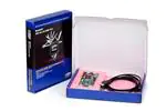
The MachXO Mini Development Kit includes:
• MachXO Mini Evaluation Board – The Mini board is a small board (about the size of a business card) with the
following on-board components and circuits:
– MachXO LCMXO2280C-4TN144C CPLD
– 2-Mbit SPI Flash memory
– 1-Mbit SRAM
– I2C temperature sensor
– USB connectors (JTAG, RS-232)
– 2x16 expansion header for general I/O, I2C, and SPI
– Push-buttons for sleep mode and global set/reset
– 4-bit DIP switch
– DAC/ADC circuit
– MachXO Sleep Mode circuit
– Eight status LEDs
• Pre-loaded Reference Designs and Demos – The kit includes a pre-loaded demo design (Mini SoC) that integrates several Lattice reference designs including the LatticeMico8 microcontroller, SRAM controller, I2C controller, SPI Flash memory controller, and a UART peripheral. Firmware supports a temperature monitor demo and,
when connected to a host PC, allows you to use a terminal program to use advanced demonstrations.
• Two USB Connector Cables – The Mini board is powered from the mini B USB port (DEBUG) when connected
to a host PC. The DEBUG port provides a general communication and debug port via a USB-to-RS-232 physical
channel. A second USB channel (PROG) provides a programming interface to the MachXO JTAG port.
• QuickSTART Guide – The MachXO Mini Development Kit QuickSTART Guide provides information on connecting the Mini board, installing Windows hardware drivers, and running the basic temperature monitor demo.
• MachXO Mini Development Kit Web Page — The MachXO Mini Development Kit web page on the Lattice web
site provides access to the latest documentation, demo designs and drivers for the kit.
The contents of this user’s guide include demo operation, top-level functional descriptions of the various portions of
the evaluation board, descriptions of the on-board connectors, switches and a complete set of schematics of the
Mini board.
2
�MachXO Mini Development Kit
User’s Guide
Figure 1. MachXO Mini Evaluation Board, Top Side
Power
LED
Header
LEDs
Debug USB
S2 Push-button
DIP Switch Bank
S1 Push-button
Program USB
I2C Temperature
Sensor
MachXO Device
This board features a MachXO PLD with a 3.3V core supply. It can accommodate all pin-compatible MachXO
devices in the 144-pin TQFP (20x20 mm) package. A complete description of this device can be found in the
MachXO Family Data Sheet.
Note: The connections referenced in this document refer to the LCMXO2280C-4TN144C device. Available I/Os
and associated sysIO™ banks may differ for other densities within this device family. However, only the
LCMXO2280C-4TN144C device offers full functional use of the entire evaluation board.
Demonstration Designs
Lattice provides three demos that illustrate key applications of the MachXO device:
• Mini SoC – Illustrates use of the LatticeMico8 microcontroller, firmware, and peripherals (UART communication,
SPI Flash memory controller, SRAM controller, and I2C peripheral controller). The Mini SoC demo design is preprogrammed into the MachXO Mini Evaluation Board by Lattice.
• MachXO Sleep Mode – Shows application of an external “sleep circuit” to cycle the low-power, sleep mode input
of the MachXO PLD.
• TransFR – Shows the Lattice transparent field reconfiguration (TransFR™) technology with the MachXO.
Note: It is very likely that you will obtain your Mini board after it has been reprogrammed. To restore the factory
default demo or program it with other Lattice-supplied examples see the Download Demo Designs and Programming Demo Designs with ispVM™ sections of this document.
Mini SoC Demo
The Mini SoC demo is pre-programmed into the non-volatile Flash memory of the MachXO PLD and is operational
upon power-up. The design provides the following features:
• Reads the on-board I2C temperature sensor and displays real-time results as a level meter onto the LED bank
(D0-D7).
• Logs temperature measurements into the on-board SRAM or non-volatile SPI Flash memory.
3
�MachXO Mini Development Kit
User’s Guide
• Displays current temperature and the most recent transaction results of the Mini board onto a host PC running a
terminal program.
The demo design integrates the following Lattice reference designs:
• RD1026, LatticeMico8 Microcontroller User’s Guide
• RD1042, WISHBONE UART
• RD1044, SPI WISHBONE Controller
• RD1046, I2C Master with WISHBONE Bus Interface
• RD1043, LatticeMico8 to WISHBONE Interface Adapter
Firmware running on the LatticeMico8 demonstrates control logic for the peripherals connected to a shared on-chip
WISHBONE bus and communication between the Mini board and a host PC connected to the USB-to-RS232
debugging path.
Figure 2. Mini SoC Block Diagram
MachXO Mini Evaluation Board
Switch Bank
LED Bank
RS-232/USB
MachXO PLD
LatticeMico8
UART
PC Host
WISHBONE Bus
SPI Memory
Controller
I2C Master
I2C
JTAG/USB
SPI
I2C Temperature
Sensor
SPI 2-Mbit
Flash Memory
SRAM Memory
Controller
SRAM
SRAM 1-Mbit
Memory
Download Windows Hardware Drivers
Before you begin, you will need to obtain the necessary hardware drivers for Windows from the Lattice web site.
To download Windows Hardware Drivers:
1. From the MachXO Mini Development Kit web page, locate the hardware device drivers for the RS-232/USB
debug interface.
2. Download the ZIP file to your system and unzip it to a location on your PC.
Linux Support:
The debug interface drivers for the evaluation board are included in Linux kernel v.2.4.20 or greater including distributions compatible with Lattice Diamond® design software (Red Hat Enterprise v.5, v.4 or Novell SUSE Enterprise
v.10).
4
�MachXO Mini Development Kit
User’s Guide
Download and Program the Mini SoC Demo Design
The Mini SoC Demo is preprogrammed into the Mini board, however over time it is likely that your board will be
modified.
To download the Mini SoC Demo source files and reprogram the Mini board:
1. See the Download Demo Designs and Programming Demo Designs with ispVM sections of this document.
2. Use .\Demo_MachXO_Mini_SoC\project\impl1\mini_soc_demo_impl1.jed to restore the Mini SoC demo
design.
Connect to the MachXO Mini Evaluation Board
Use the USB cables provided to connect the evaluation board to your PC:
1. Connect one USB cable from a USB port on your PC to the board’s RS-232/USB Debug socket (DEBUG-J8)
on the top-left side of the board as shown in Figure 2. After connection is made, a blue Power LED (PWR) will
light up indicating the board is powered on.
2. If you are prompted, “Windows may connect to Windows Update” select No, not this time from the available
options and click Next to proceed with the installation. Choose the Install from specific location (Advanced)
option and click Next.
3. Select Search for the best driver in these locations and click the Browse button to browse to the Windows
driver folder that has been created (see the Download Windows Hardware Drivers section of this document).
Select the CDM 2.04.06 WHQL Certified folder and click OK.
4. Click Next. A screen will display as Windows copies the required driver files. Windows will display a message
indicating that the installation was successful.
5. Click Finish to install the USB driver. A second “Found New Hardware” screen will appear.
6. Repeat instructions 2-4 to install the USB-to-Serial Port driver.
Setup Windows HyperTerminal
Windows HyperTerminal is a terminal program found on most PCs that can be used to communicate with the Mini
board.
To set up Windows HyperTerminal:
1. From the Start menu, select Control Panel > System. The System Properties dialog appears.
2. Select the Hardware tab and click Device Manager. The Device Manager dialog appears.
5
�MachXO Mini Development Kit
User’s Guide
3. Expand the Ports (COM & LPT) entry and note the COM port number for the USB Serial Port.
4. From the Start menu, select Programs > Accessories > Communications > HyperTerminal. The HyperTerminal application and a Connection Description dialog appear.
5. Specify a Name and Icon for the new connection. Click OK. The Connect To dialog appears.
6
�MachXO Mini Development Kit
User’s Guide
6. Select the COM port identified in Step 3 from the Connect using: list. Click OK. The COMn Properties dialog
appears where n is the COM port selected from the list.
7. Select the following Port Settings.
Bits per second:
Data bits:
Parity:
Stop bits:
Flow control:
115200
8
None
1
None
Click OK. The HyperTerminal window appears.
8. From the Mini board, press the S1 push-button (Reset). The Mini SoC demo Main Menu appears in HyperTerminal.
7
�MachXO Mini Development Kit
User’s Guide
=========================================================================
Welcome to the MachXO Mini Evaluation Board
Mini SoC Demonstration Rev 1.0, February 2009
Main Menu
-----------------------------------------------------------0: Re-display Main Menu
1: Read SPI Flash Memory IDCode
2: Read I2C Temperature Sensor
3: Read DIP Switch Bank
4: Normalize Temperature Output
5: Read Data History from SRAM
6: Copy Data History from SRAM to SPI Flash Memory
7: Read Data History from SPI Flash Memory
Press 0-7 to select an option.
=========================================================================
Set Up Linux Minicom
Minicom is a terminal program found with most Linux distributions. It can be used to communicate with the Mini
board.
To setup Minicom:
1. Check active serial ports:
#dmesg | grep tty
Note the tty label assigned to the USB port.
2. From a command prompt, start Minicom:
#minicom -s
The configuration menu appears.
3. Highlight Serial port setup and press Enter. Serial port settings appear.
4. Press A (Serial Device). Specify the active serial device noted in Step 1 and press Enter.
5. Press E (Bps/Par/Bits). Specify 115200, None, 8 and press Enter.
6. Press F (Hardware Flow Control). Specify None and press Enter.
7. Press Esc. The configuration menu appears.
8. Select Save setup as dfl. Minicom saves the port setup as the new default.
9. Select Exit. The Minicom interface appears.
10. From the Mini board, press the S1 push-button (Reset). The Mini SoC demo Main Menu appears.
Scan the SPI Flash Memory IDCode
This demo uses the SPI Flash Memory Controller and UART modules of the Mini SoC to scan the memory device
identification code of the on-board SPI Flash Memory and display it on the terminal output. The transaction is
logged to the on-board SRAM through the SRAM controller module.
8
�MachXO Mini Development Kit
User’s Guide
To scan the SPI Flash Memory IDCode:
1. From the terminal Main Menu, press 1.
The ID number is returned as a hex value and the transaction is logged to the on-board SRAM and the current
address pointer is indicated.
Example:
ID:0x12
(SRAM ADDR:0x00010)
Note: The ID for your board may differ.
Reading the I2C Temperature Sensor
This demo uses the I2C Controller and UART modules of the Mini SoC to read the on-board I2C temperature sensor, convert the raw data to Celsius units and display it on the terminal output. The transaction is logged to the onboard SRAM through the SRAM controller module.
To monitor temperature:
1. From the terminal window press 4. The Mini SoC normalizes the meter output for the ambient temperature and
lights 4 (D0-D3) of the LED bank (D0-D7).
2. Place your finger on the on-board I2C Temperature Sensor (U14) for 2 to 5 seconds. Depending on your skin
temperature, the level should influence the temperature monitor (1 LED = 0.25°C).
3. From the terminal window, press 2. The current temperature in degrees Celsius appears and the transaction is
logged to the on-board SRAM and the current address pointer is indicated.
Example:
Temp:30.50°C
(SRAM ADDR:0x0000B)
Reading the DIP Switch Bank
This demo uses the UART module of the Mini SoC to read the user-input switch inputs 1-3 of the DIP Switch Bank
(SW1) and output it to the terminal as a hex value. The transaction is logged to the on-board SRAM through the
SRAM controller module.
Note: SW1D (Schematic Sheet 3 of 8) of SW1: SW_SPST_4 is reserved to enable/disable the on-board Sleep
Mode circuit.
To read the DIP Switch:
1. From the terminal window press 3. The switch setting is returned as a hex value and the transaction is logged
to the on-board SRAM.
Example:
SW:0x0
(SRAM ADDR:0x0000A)
Reading the Transaction Data History from On-Board SRAM
This demo uses the SRAM controller module of the Mini SoC to read the transaction history logged to on-board
SRAM during the period the Mini board has been powered.
9
�MachXO Mini Development Kit
User’s Guide
To read data history from SRAM:
1. From the terminal window press 5. The transaction log is listed.
Example:
SRAM:
Temp:30.50°C
ID:0x12
SW:0X0
Copy Data History from On-Board SRAM to SPI Flash Memory
This demo uses both the SRAM and SPI Flash Memory controller modules of the Mini SoC to copy the transaction
history logged to the volatile on-board SRAM to the non-volatile on-board SPI Flash Memory.
To copy data history from SRAM to SPI Flash memory:
1. From the terminal window press 6. The data log is transferred and the terminal indicates “Done”.
Example:
Done.
SPI Flash:
Temp:30.50°C
ID:0x12
SW:0X0
Read SPI Flash Memory
This demo uses the SPI Flash Memory controller module of the Mini SoC to read the on-board SPI Flash Memory.
To illustrate the non-volatile nature of the Flash memory, you may power-off the Mini board at any time by disconnecting both USB cables. Reattach the cables, restart the terminal application, and then perform the memory read
to confirm the data is intact.
To read data history from SRAM:
1. From the terminal window press 7. The transaction log is listed.
Example:
SPI Flash:
Temp:30.50°C
ID:0x12
SW:0X0
Note: To clear the Flash memory, press SW1 to reset the Mini board and clear the on-board SRAM. Copy data
history (currently cleared) from the SRAM to the Flash memory.
Re-Display the Main Menu
During the demo session the main menu will scroll off-screen. To redisplay the menu, press 0.
You may confirm that the SPI Flash memory will retain data in a power-off condition by removing both USB cables
to power-down the Mini board. Rerun the memory read to confirm the data is intact.
While the Mini board is powered, a running log of all transactions is logged to the on-board SRAM.
10
�MachXO Mini Development Kit
User’s Guide
MachXO Sleep Mode Demo
The MachXO sleep mode demo illustrates one possible implementation for power savings. Using this method, the
MachXO device provides supervisory logic to control its own SLEEPN pin. Periodically, the device becomes active
to monitor a trigger event. If the event is not present, it deactivates to save power.
When the SLEEPN pin is asserted (low), the following occur:
• The device powers down internally, dropping power consumption to less than 100µA
• All I/Os are tristated
When the SLEEPN pin is de-asserted (high), power is restored and the MachXO is reconfigured and ready to operate in 1ms or less. Due to the dramatic reduction in power consumption and the fast “instant-on” capability, a
scheme can be implemented with a few simple, inexpensive external components deactivate the device and reactivate with a duty cycle ratio that saves substantial power.
Figure 3. Sleep Circuit (Abbreviated)
MachXO
R56
10K
C60
0.33uF
S1
I/O (14)
I/O (89)
Q5
R59
10K
C59
33uF
R20
10K
SW1D
SLEEPN (70)
When I/O pin 89 goes low, C60 discharges. PNP transistor Q5 then conducts, discharging C59. Provided SW1D is
closed, this value is forced onto the SLEEPN pin of the MachXO device, putting it into low power sleep mode.
Once in sleep mode, all I/O pins are tristated, allowing C60 to slowly charge. This then turns off Q5 and allows C59
to charge. Once the amount of charge is sufficient to place a logic high level on SLEEPN, the device returns to normal operating mode.
The MachXO begins operating, as defined by its programmed function. In this demonstration, I/O pin 89 is driven
high initially to allow the device an opportunity to remain active long enough to check whether switch S1 is pressed.
If S1 is not pressed, I/O pin 89 is driven low and the cycle repeats.
If S1 is pressed at that moment, the device remains operational for the entire cycle of an internal counter (~3 sec)
and the LEDs are illuminated during this time. S1 is then checked after each subsequent cycle.
To exit sleep mode or to reprogram the device, open switch SW1D (SW1-4).
Download and Program the MachXO Sleep Mode Demo Design
To download the MachXO Sleep Mode Demo source files and reprogram the Mini board:
1. See the Download Demo Designs and Programming Demo Designs with ispVM sections of this document.
2. Use .\Demo_MachXO_Mini_Sleep\project\impl1\mini_auto_sleep_impl1.jed to restore the MachXO Sleep
Mode demo design.
11
�MachXO Mini Development Kit
User’s Guide
Operating the Sleep Mode Demo
To operate the Sleep Mode Demo:
1. To observe the sleep/wake power savings, place voltmeter leads across J2 (VCC CORE) or J3 (VCC AUX).
Each number attaches across a 0.2 ohm resistor between the +3.3V supply rail and VCC_CORE or
VCC_AUX. The average voltage level will drop significantly during the sleep/wake cycle. You may estimate current consumption with Ohm’s Law where I = V / 0.2 ohms.
2. Toggle SW1_1 (A), SW1_2 (B), and SW1_3 (C) to the OFF position. All user LEDs D7-D2 are dim and user
LED D1-D0 are lit. The DIP switch inputs 1-3 are tied directly to the LED bank according to the table below.
SW1
LED
N/A
0, 1 (ON)
_1 (A)
2, 5
_2 (B)
3, 6
_3 (C)
4, 7
3. Adjust DIP switches 1-3 and note the pattern on the LED array.
4. Enable the MachXO Sleep Mode circuit, toggle the SW1D (4) to the ON position. The MachXO enters a
sleep/wake cycle.
According to the parameters of the external Sleep Mode circuit the MachXO will periodically wake to check for
user input and drive the LED bank. If no inputs have changed it will return to the sleep state. The LED bank will
flicker during the sleep/wake cycle.
5. Depress SW1. The MachXO wakes for ~3s and the LED array is lit according the SW1 values. Once the SW1
is released the Mini board reverts to the sleep/wake cycle.
To exit sleep mode or to reprogram the device, open switch SW1D (4).
Note: Pressing push-button SW2 will assert the dedicated MachXO SLEEPN input with any design.
TransFR Demo
This demo illustrates the TransFR (TransparentFieldReconfiguration) feature of the MachXO PLD. The TransFR
solution uniquely allows logic to be updated in the field without interrupting system operation.
The demo first programs the MachXO device with a count-up function, which drives eight LEDs. It then freezes
these outputs while a count-down function is loaded into the device’s SRAM configuration space. The demo then
concludes by releasing the outputs to display the count-down function.
The TransFR feature allows the MachXO to lock its I/Os in a deterministic state while a new configuration is loaded
into the device’s SRAM configuration space. This minimizes system interruption by dynamically configuring the
MachXO with a new pattern without tri-stating its output pins.
The inputs for the incrementing and decrementing design are:
• CLK: Clock to drive the counter and internal logic
• RSTn: Resets counter to 0, asserted low.
• CNTEN: Enables counting when asserted high.
• CAP_EN: Captures the counter value on LEDs when asserted high.
• LOADn: When asserted high, enables the counter values to be displayed on LEDs. When asserted low, this
input tristates the pins that drive the LEDS, and forces a synchronous load of the values captured by the
CAP_EN.
12
�MachXO Mini Development Kit
User’s Guide
The CLK connects directly to the oscillator on the board. The RSTn (global reset) is connected to user push-button
(S1) of the Mini board. The other three inputs come from the SW1 DIP switch bank at the right hand side of the Mini
board.
The outputs of the MachXO device are as follows:
• LED_OUT[7:0]: Most significant eight bits of the counter to be displayed through eight LEDs to show the counter
values in binary format.
Download the TransFR Demo Design
To download the TransFR Demo source files, see the Download Demo Designs section of this document.
Programming the Initial Up-Counter Design
To program the up-counter design JEDEC file:
1. Set the control signals with the Mini board SW1 DIP switches as follows:
• LOADn (SW1_1) is set to 1 (OFF)
• CNTEN (SW1_2) is set to 0 (ON)
• Cap_en (SW1_3) is set to 0 (ON)
2. Use ispVM to download the Mini board with the .\Demo_MachXO_Mini_TransFR_Up_Counter\project\up_count.jed file.
See the Programming Demo Designs with ispVM section of this document for details on programming the Mini
board with ispVM.
The up-counter design is first loaded into Flash then immediately into SRAM space. In doing so, the LEDs will
light up, showing the initial value of the counter (all 1s). The SRAM and Flash configuration spaces are now
both programmed with the count-up function.
3. Toggle SW1_2 CNTEN to the OFF (1) position. The LEDs show the up-counter values.
In the following procedure you will load a down-count function into the MachXO Flash program space. After the
TransFR operation is complete, the down-counter results will be displayed on LEDs.
4. Toggle SW1_2 CNTEN to the ON (0) position. Note the up-counter value.
Download the Down-Counter Design to the MachXO Flash Space
To program the down-counter design JEDEC file:
1. From ispVM System, choose ispTools > Scan Chain. The New Scan Configuration Setup window appears.
2. Double-click the LCMXO2280C entry in the Device List. The Device Information dialog appears.
3. From the Data File section click the Browse button. The Open Data File dialog appears.
4. Browse to the .\Demo_MachXO_Mini_TransFR_Down_Counter\project folder, select down_count.jed, and
click the Open button.
5. From the Device Access Option section, choose Flash Background Mode.
13
�MachXO Mini Development Kit
User’s Guide
6. From the Operation section, choose: XFLASH Erase, Program, Verify, and click OK.
7. Choose Project > Download. ispVM reprograms the Mini board.
Programming requires about 20 to 40 seconds. A small timer window will appear to show elapsed programming time. At the end of programming, the configuration setup window should show a “PASS” in the “Status”
column.
The down-counter program is now loaded into the Flash configuration space. Since the up-counter function is
still programmed into the SRAM configuration space, the count up function still appears on the LED bank. The
count-down function will be loaded in the SRAM space when the TransFR operation is performed in the next
procedure.
Transfer the MachXO Flash to SRAM Space
At this point in the demo, the down-counter function is loaded into the Flash configuration space, and the up-counter function is loaded into the SRAM space. In this section, an *.svf file is generated and used in the ispVM SVF
debugger tool. The debugger tool steps through the SVF file to lock the I/Os at their current state (via TransFR
technology), load the Flash configuration space into the SRAM space, then release the I/Os. This allows the loading of a new configuration without the I/Os ever having been tri-stated.
To prepare the transfer of Flash configuration contents to the SRAM space of the MachXO:
1. From ispVM System, choose ispTools > Scan Chain. The New Scan Configuration Setup window appears.
2. Double-click the LCMXO2280C entry in the Device List. The Device Information dialog appears.
3. From the Device Access Options section select Flash Background Mode.
4. From the Operation section select XFLASH TransFR.
5. Click on the Expand button.
14
�MachXO Mini Development Kit
User’s Guide
6. From the I/O State section, select Leave Alone. Click OK.
7. Choose File > Save As... The Save As .XCF File dialog appears.
8. Browse to the .\Demo_MachXO_Mini_TransFR_Down_Counter\project directory, specify TransFR.xcf and
choose Save.
9. Choose Project > Generate SVF File... The Generate SVF File dialog appears.
10. From Source File (*.xcf) section, choose the Browse button. The Browse Source *.XCF file dialog appears.
11. Browse to the .\Demo_MachXO_Mini_TransFR_Down_Counter\project directory, choose the TransFR.xcf
file and click Open.
12. From the Save SVF File as: section, choose the Browse button. The Browse SVF File dialog appears.
13. Specify TRANSFR.svf file and choose the Save button.
14. Click the Generate button. ispVM reports: Build Single SVF File: Successful.
15. Click OK and click the Close button.
You have now built the TransFR serial vector format (SVF) file that you will use in the ispVM SVF Debugger program.
To transfer the Flash configuration contents to the SRAM space of the MachXO:
1. Choose ispTools > SVF Debugger... The SVF Debugger application initial Svf File1 screen appears.
2. Choose File > Open. The Open Data File dialog appears.
3. Browse to the to the .\Demo_MachXO_Mini_TransFR_Down_Counter\project directory, choose the
TransFR.svf file, and click Open. The TransFR.svf code appears in the SVF Debugger window.
4. Choose Configuration > Cable and IO Port Setup... The Cable and IO Port Setup dialog appears.
5. Click the Auto-Detect button. The SVFDebugger detects the EzUSB port and USB cable.
15
�MachXO Mini Development Kit
User’s Guide
6. Click OK.
7. Place the cursor at the top of the file, above the first instruction. This will ensure that you step through all the
instructions in order.
8. Press the Step key F11 (Command > Step). The SVF Debugger advances to the next line of executable code.
9. Step 2-3 more times. Each time you click the STEP button, it executes an instruction, then advances to the next
instruction. Each time you step through an instruction, it is translated, goes through the USB download cable,
and is executed in the MachXO device.
10. Continue to slowly step through the code and stop just before getting to the instruction that reads (about Line
51):
! Shift in ISC ERASE(0x03) instruction
SIR 8
TDI
(03);
Note that LEDs are still counting up. Now step once while watching the displays. Note that the displays have
stopped. The device outputs are now under boundary scan control. A TransFR operation (embedded in the just
executed instruction) has locked the outputs at whatever count values they were at when the TransFR action
occurred.
11. From the Mini board, toggle the SW1_2 CNTEN to the ON (0) position. This will stop the counter from counting
once the device is out of the boundary scan mode.
12. Press F11 until the cursor highlights the BYPASS instruction:
! Shift in BYPASS(0xFF) instruction
SIR
8
TDI (FF);
13. Press F11 once more. The cursor highlights:
RUNTEST IDLE...;
At this point, the new pattern has been loaded into the SRAM memory space and the switch inputs are monitored, but the outputs are still controlled by boundary scan and are still frozen at the same values.
14. Press F11. SVFDebugger reports “Process Done. No Error”. Click OK.
The MachXO I/Os are now released from boundary scan control and counter’s initial value (0xFF) is driven to
the LED displays. The displays do not start counting yet because the CNTEN is deasserted.
15. From the Mini board, toggle the SW1_2 CNTEN to the OFF (1) position. The LED display starts counting down
from the initial value.
The MachXO has exchanged the up-counter for the down-counter function, without disrupting the output PIOs.
Another variation of the demo is to initialize the down-counter with the current state of the up-counter. After step 12
in the procedure, toggle CAP_EN (SW1_3) up and down once (toggle from ‘ON’ (0) to ‘OFF’ (1) and back to ‘ON’
(0)), then toggle LOADn (SW1_1) down and up once (go from ‘OFF’ (1) to ‘ON’ (0) and back to ‘OFF’ (1)). Following step 14, the counter value displayed on the LEDs will not change. Following Step 15, the down-counter will
begin from the value displayed on the LED bank.
Note: See TN1087, Minimizing System Interruption During Configuration Using TransFR Technology for more
information.
16
�MachXO Mini Development Kit
User’s Guide
Download Demo Designs
Lattice distributes source and programming files for a variety of demonstration designs compatible with the Mini
board.
To download demo designs:
1. Browse to the MachXO Mini Development Kit web page of the Lattice web site. Select the Demo Applications
download and save the file.
2. Extract the contents of MachXO_Mini_Dev_Kit.zip to an accessible location on your hard drive. Four demo
design directories (Demo_MachXO_Mini_) are unpacked.
Demo
Directories
Mini SoC Demo
Demo_MachXO_Mini_SoC
.\project
.\source
.\LatticeMico8_V3_0_Verilog
.\RD1042
.\project
.\source
.\RD1043
.\project
.\source
.\RD1044
.\project
.\source
.\RD1046
.\project
.\source
MachXO Sleep Mode
Demo_MachXO_Mini_Sleep
.\project
.\source
TransFR
Demo_MachXO_Mini_TransFR_Down_counter
.\project
.\source
Demo_MachXO_Mini_TransFR_Up_counter
.\project
.\source
Where:
• \project – Diamond project (.ldf), preferences (.lpf), and programming file (.jed). This directory may contain intermediate results of the Diamond build process.
• \source – HDL source for the Diamond project.
• .\LatticeMico8_V3_0_Verilog – LatticeMico8 Microcontroller User’s Guide (RD1026).
• .\RDxxxx – Reference designs integrated by the Mini SoC Demo.
Programming Demo Designs with ispVM
This section describes the programming procedure to program the MachXO device using ispVM. If you have Lattice Diamond 1.3 installed, then you must download the latest version of the ispVM System device programming
software. Click here to install the latest version of the ispVM System software. Diamond 1.3 comes with a programming tool called Diamond Programmer. This tool does not have a SVF debugger (see Release Notes on the Lattice
website).
The Mini SoC demo design is pre-programmed into the Mini board by Lattice. To restore a Mini board to factory settings or load an alternative demo design, use the procedure described in this section.
17
�MachXO Mini Development Kit
User’s Guide
To program a demo programming file:
1. Connect the Mini board to a host PC using both USB DEBUG and PROG ports.
2. From the Mini board toggle SW1D to the OFF position.
3. From the Start menu run ispVM System. ispVM appears.
4. Choose Options > Cable and IO Port Setup... The Cable and I/O Port Setup dialog appears.
5. Click Auto Detect. ispVM will detect Cable Type USB and Port Setting EzUSB.
6. Click OK.
7. Choose ispTools > Scan Chain. The New Scan Configuration Setup window appears. The LCMXO2280C
appears in the device list.
8. Right-click the LCMXO2280C entry and choose Edit Device... The Device Information dialog appears.
9. From the Data File section, click the Browse button. The Open Data File dialog appears.
18
�MachXO Mini Development Kit
User’s Guide
10. Browse to the \project folder, select .jed, and click Open. From the Operation list
choose Flash Erase, Program, Verify and click OK.
11. Choose Project > Download. ispVM reprograms the Mini Board.
Programming requires about 20-40 seconds. A small timer window will appear to show elapsed programming
time. At the end of programming, the configuration setup window should show a “PASS” in the “Status” column.
Rebuilding a Demo Project with Lattice Diamond Design Software
Use the procedure described below to rebuild any of the demo projects for the MachXO Mini Evaluation Board.
1. Install and license Diamond software
2. Install and license ispVM System software.
3. Download the demo source files from the MachXO Mini Development Kit web page.
4. Run the Diamond design tool.
5. Create a new project and add the HDL files from the \source directory. Note that some demos provide
a .ldf project file.
6. Import the logical preference file (.lpf) with I/O plan and timing requirements.
7. Run the Generate Data File (JEDEC) process.
8. See the MachXO Sleep Mode Demo section of this document for details on downloading a programming file to
the Mini board.
19
�MachXO Mini Development Kit
User’s Guide
Reassembling the Demo LatticeMico8 Firmware
Use this procedure to reassemble and download changes to the LatticeMico8 microcontroller firmware.
1. Install the LatticeMico8 Tool Code Revision 3.0.
Note: The LatticeMico8 tool executables are also provided in the
. \Demo_MachXO_Mini_SoC\LatticeMico8_V3_0_Verilog\utils directory.
2. Optional Compile the LatticeMico8 Assembler and Simulator
3. Modify the Assembly source (.s) file and recompile to a memory image (.hex). Source for the Mini SoC demo is
provided as mini_soc_demo.s.
4. Use the Memory Initialization tool of the Diamond design software to update the physical database NCD.
5. Rerun Generate Data File (JEDEC) process.
6. See the Programming Demo Designs with ispVM section of this document for details on downloading a programming file to the Mini board.
MachXO Mini Evaluation Board
This section describes the features of the MachXO Mini Evaluation Board in detail.
Overview
The Mini board is a complete USB-powered development platform for the Lattice MachXO PLD. The board includes
on-board SRAM and SPI Flash memory, I2C and SPI microcontroller communication interfaces, a USB program/debug port, and an expansion header to support test connections.
Figure 4. MachXO Mini Evaluation Board Block Diagram
SLEEPN
2x16
Header
30
I2C Temp.
Sensor
3
I2C/SMBus
4
SPI 2 Mbit
Flash
4
SPI
8
GSRN/IO
Push-button
16 GPIO
1 Mbit
SRAM
A/Mini-B
USB Cable
USB Mini-B
Socket
Push-button
USB
Controller
28
MachXO
LCMXO2280C-4TN144C
20
8 LEDs
25 MHz
Crystal
2
ADC/DAC
Circuit
3
Sleep
Circuit
Serial
Debugging
JTAG
Programming
4-Bit
DIP Switch
A/Mini-B
USB Cable
USB to Serial
(RS-232)
USB Mini-B
Socket
�MachXO Mini Development Kit
User’s Guide
Table 1 describes the components on the board and the interfaces it supports.
Table 1. MachXO Mini Evaluation Board Components and Interfaces
Component/Interface
Type
Schematic Reference
Description
Circuits
USB Controller
Circuit
U3:CY7C68013A-QFN56
USB-to-JTAG interface
USB to Serial (RS-232)
Circuit
U1:FT232R / 32-QFN
USB-to-Serial interface
25 MHz Crystal
Clock
X2:25 MHz
MachXO clock source
1Mbit SRAM
Memory
U8:CY128X8TSOP
1Mb of SRAM
MachXO PLD
PLD
U16:MachXO_2280_TQ144
LCMXO2280T144
I2C Temperature Sensor
I/O
U14:TMP101
Measures board temperature
2Mbit SPI Flash Memory
Memory
U11
2Mb FLASH memory
8 LEDs
Output
D7-D0
User-definable LEDs
2x16 Header
I/O
J6
User-definable I/O
USB Mini B Sockets
I/O
J1, J8
Programming and debug interface
Push-button switches
I/O
S1, S2
GSR and Sleep push buttons
Jumper
I/O
J2
MachXO Core current
Jumper
I/O
J3
MachXO AUX current
Jumper
I/O
J4
MachXO I/O current
Jumper
I/O
J5
MachXO TSALL input
Components
Interfaces
Subsystems
This section describes the principle subsystems for the Mini board in alphabetical order.
Clock Sources
Three clock sources are available to the MachXO, an unconditioned input from a 25MHz crystal or a 48MHz originating from the FTDI USB Device controller.
Table 2. Clock Sources Pin Information
Source
Frequency
(MHz)
Description
MachXO
Pin
FTDI USB Device U1
48
Available only when DEBUG connector J8 is connected to a USB host.
124
Cypress USB Device U3
48
Available only when PROG connector J1 is connected to a USB host.
127
Crystal X2
25
Crystal 25MHz. See Figure 5 for MachXO logic required for the X2 connection.
21
23, 22
�MachXO Mini Development Kit
User’s Guide
Figure 5. MachXO Logic for Crystal X2 Connection
MachXO
Pin 22
LVCMOS33 Output
Crystal + RC
Network
Pin 23
LVCMOS33 Input
Internal Pullup Disabled
DIP Switch
The evaluation board includes a 4-bit input toggle switch located on the right side of the board. Three are available
as general purpose inputs. When in the ON position, a connection to ground is made for a logical low input to the
corresponding MachXO pin. When open, the line is pulled high through external resistors.
Table 3. DIP Switch Reference
Item
Description
Reference Designators
SW1
Part Number
219-4MST
Manufacturer
CTS
Web Site
www.ctscorp.com
Table 4. DIP Switch Pin Information
SW1
Description
MachXO Pin
A/1
User-defined.
92
B/2
User-defined.
91
C/3
User-defined.
90
D/4
Connected to MachXO sleep circuit.
70
Expansion Header
The expansion header provides 25 user I/Os connected to the MachXO, five for the on-board SPI bus, and three for
the on-board I2C/SMBus. The remaining pins serve as power and clock supplies for expansion boards. The expansion connector is configured as one 2x16 100mil centered pin header.
Eight pins of the MachXO top bank (which provides PCI clamp support) and eight pins of the left or right bank (differential output support) are connected to the connector.
Table 5. Expansion Connector Reference
Item
Description
Reference Designators
J6
Part Number
90131-0800
Manufacturer
Molex/Waldom Electronics
Web Site
www.molex.com
22
�MachXO Mini Development Kit
User’s Guide
Table 6. Expansion Header Pin Information
J6 Pin
Function
MachXO Pin
1
+3.3V
—
2
+3.3V
—
3
8
80
4
0
119
5
9
78
6
1
116
7
10
79
8
2
114
9
11
76
10
3
113
11
12
77
12
4
112
13
13
74
14
5
111
15
14
75
16
6
110
17
15
73
18
7
109
19
I2C Alert
120
20
Clock
127
21
I C Data
122
22
SPI Chip Select
87
2
2
Other Connections
Temp Sensor U14
Notes
2.2K external pull-up.
48MHz clock from Cypress USB device.
Temp Sensor U14
2.2K external pull-up.
SPI CS signal for expansion header.
23
I C Clock
121
Temp Sensor U14
2.2K external pull-up.
24
SPI Clock
85
SPI Flash U11
Shared SPI Interface.
81
SPI Flash U11
Shared SPI Interface.
SPI Flash U11
Shared SPI Interface.
25
Reserved
26
SPI Data Output
27
Reserved
28
SPI Data Input
84
29
GND
—
30
GND
—
31
Analog Input
—
Comparator U15
32
PWM Output
—
Transistor Q3
Output as high as 5V1.
1. MachXO I/O pins are not 5V tolerant. This signal should not be connected to any MachXO pins.
I2C Temperature Sensor
The temperature sensor is a TI TMP101NA/250 device. It uses an I2C/SMBus interface to provide the temperature
reading on the board. The temperature sensor is located in the lower-right corner of the board.
Table 7. I2C Temperature Sensor Reference
Item
Description
Reference Designators
U14
Part Number
TMP101NA/250
Manufacturer
TI
Web Site
www.ti.com
23
�MachXO Mini Development Kit
User’s Guide
Table 8. I2C Temperature Sensor Pin Information
Function
Direction
U14 Pin
Description
MachXO Pin
SCL
I/O
1
Pulled high through 2.2K resistor pack RN2.
121
SDA
I/O
6
Pulled high through 2.2K resistor pack RN2.
122
ALERT
O
3
Pulled high through 2.2K resistor pack RN2.
120
ADD0
I
5
Hard-wired high.
—
JTAG Programming Interface
A USB B-type mini socket on the board serves as the JTAG programming interface.
For JTAG programming, a preprogrammed Cypress CY7C68013A USB peripheral controller, and boot PROM are
provided on the Mini board to serve as the programming interface to the MachXO PLD. Programming requires the
ispVM System software. The programming connection will appear to the ispVM System software as if a regular
USB-based ispDOWNLOAD cable is connected to the PC.
Table 9. JTAG Programming Reference
Item
Description
Reference Designators
U2
Part Number
CY7C68013A-56LFXC
Manufacturer
Cypress
Web Site
www.cypress.com
Table 10. JTAG Programming Pin Information
Signal Name
Description
MachXO Pin
XO_TDO
Test Data Output
47
XO_TDI
Test Data Input
51
XO_TMS
Test Mode Select
39
XO_TCK
Test Clock
42
Jumpers
One jumper is provided on the right side of the board for general use. When a jumper is installed, a connection to
ground is made. When the jumper is removed, the line is pulled high through an external resistor.
Table 11. Jumper Reference
Item
Description
Reference Designators
J5
Part Number
Jumpers Red 1x2
Manufacturer
Tyco Electronics AMP
Web Site
www.tycoelectronics.com
Table 12. Jumper Pin Information
Item
Notes
MachXO Pins
J5
MachXO TSALL pin, can also be used as general-purpose I/O.
24
J4
VCCIO current
135, 117, 98, 82, 38, 63, 10, 26
J3
VCCAUX current
53, 128
J2
VCCCORE current
21, 52, 93, 129
24
�MachXO Mini Development Kit
User’s Guide
MachXO PLD
The MachXO PLD device (LCMXO2280C-4TN144C) on the board provides 2280 LUTs, 7.5 Kbits of distributed
RAM, 27.6 Kbits of EBR SRAM and 101 user I/Os in an 8x8 mm chip scale package.
Table 13. MachXO PLD Reference
Item
Description
Reference Designators
U1
Part Number
LCMXO2280C-4TN144C
Manufacturer
Lattice Semiconductor
Web Site
www.latticesemi.com
Power Supply
A single 3.3V supply voltage for the board components is provided from the USB DEBUG connection.
Push-buttons
The board has two user push-button switches (S1 and S2). S1 connects to the GSRN pin which asserts the Global
Set/Reset input on the MachXO. In order for the GSR to operate, it is necessary to instantiate the GSR macro in
the VHDL/Verilog HDL source, otherwise it may be used as a general input pin. S2 is routed to the SLEEPN pin
which asserts the MachXO Sleep Mode. Both push-buttons are normally pulled high, and when pressed are
asserted to ground.
Table 14. Push-button Reference
Item
Description
Reference Designators
S1, S2
Part Number
EVQ-Q2K03W
Manufacturer
Panasonic ECG
Web Site
www.panasonic.com/industrial/components/components.html
Table 15. Push-button Pin Information
Button
Description
MachXO Pin
S1
MachXO GSRN or general-purpose I/O.
14
S2
Connected to MachXO SLEEPN pin.
70
RS-232 Interface
For serial communications and on-chip debugging a FTDI USB-RS232 converter provides an RS-232-like serial
communication interface between a PC host and an embedded system running in the MachXO.
Table 16. RS-232 Interface Reference
Item
Description
Reference Designators
U1
Part Number
FT232R
Manufacturer
FTDI (Future)
Web Site
www.ftdichip.com
25
�MachXO Mini Development Kit
User’s Guide
Table 17. RS-232 Interface Pin Information
Function
Direction
U1 Pin
Description
MachXO Pin
TXD
O
30
Transmit Data
7
RXD
I
2
Receive Data
6
RTS#
O
32
Request to Send
5
CTS#
I
8
Clear to Send
4
DTR#
O
31
Data Terminal Ready
1
DSR#
I
6
Data Set Ready
2
DCD#
I
7
Data Carrier Detect
3
RI#
I
3
Ring Indicator
8
SPI Flash Memory
The board is populated with a Numonyx/ST Micro non-volatile 2-Mbit SPI Flash memory located near the upperright corner of the board.
Table 18. SPI Flash Memory Reference
Item
Description
Reference Designators
U11
Part Number
M25PE20-VMN6TP
Manufacturer
Numonyx/ST Micro
Web Site
www.numonyx.com
Table 19. SPI Flash Memory Pin Information
Function
Dir
U11 Pin
Description
MachXO Pin
S#
I
1
SPI Flash chip select.
86
C
I
6
SPI Flash dlock input.
85
D
I
5
SPI Flash data input.
84
Q
O
2
SPI Flash data output.
81
W#
I
3
Hard-wired high.
—
RESET#
I
7
Hard-wired high.
—
SRAM
The board is populated with a Cypress 1-Mbit (128K x 8) Static RAM with a data bus width of 8 bits. The 15-bit
address bus, the data bus and the control signals are connected directly to the CPLD. The 15-bit address bus,
named MEMORY_A0 through MEMORY_A14, addresses 1-byte locations.
A 1Mb asynchronous SRAM is located at the bottom-center of the board.
Table 20. SRAM Reference
Item
Description
Reference Designators
U8
Part Number
CY7C1019DV33-10ZSXI
Manufacturer
Cypress
Web Site
www.cypress.com
26
�MachXO Mini Development Kit
User’s Guide
Table 21. SRAM Pin Information
Function
Direction
U8 Pin
Description
MachXO Pin
A0
I
1
Address Inputs to SRAM
50
A1
I
2
54
A2
I
3
55
A3
I
4
56
A4
I
13
57
A5
I
14
58
A6
I
15
60
A7
I
16
61
A8
I
17
62
A9
I
18
65
A10
I
19
66
A11
I
20
67
A12
I
21
69
A13
I
29
68
A14
I
30
71
A15
I
31
72
A16
I
32
IO0
I/O
6
36
Data to/from SRAM
40
IO1
I/O
7
41
IO2
I/O
10
43
IO3
I/O
11
44
IO4
I/O
22
45
IO5
I/O
23
46
IO6
I/O
26
48
IO7
I/O
27
CE#
I
5
Chip Enable to SRAM
49
17
OE#
I
28
Output Enable to SRAM
18
WE#
I
12
Write Enable to SRAM
19
User LEDs
Eight red LEDs can be used for custom status signaling. The LEDs are located at the top of the board, next to the
expansion header. Each LED illuminates when the corresponding pin on the MachXO is driven low.
Table 22. User LEDs Reference
Item
Description
Reference Designators
D7-D0
Part Number
LTST-C190CKT
Manufacturer
Lite-On
Web Site
www.liteonit.com
27
�MachXO Mini Development Kit
User’s Guide
Table 23. User LED Pin Information
Signal Name
Description
MachXO Pin
D7
User-defined
144
D6
User-defined
143
D5
User-defined
142
D4
User-defined
141
D3
User-defined
140
D2
User-defined
139
D1
User-defined
138
D0
User-defined
137
Programming
Programming for the MachXO device is controlled using the ispVM System software. Refer to the ispVM System
software for help regarding operation of this software.
The MachXO Mini Evaluation Board is equipped with a built-in USB-based programming circuit. This consists of a
USB PHY and a USB connector. When the board is connected to a PC with a USB cable, it is recognized by the
ispVM System software as a “USB Download Cable”. The MachXO PLD can then be scanned and programmed
using the ispVM System software.
Software Requirements
You should install the following software before you begin developing designs for the evaluation board:
• Lattice Diamond design software
• Latest version of ispVM System software
(Click here to install the latest version of the ispVM System software)
Mechanical Specifications
Dimensions: 3 1/2 in. [L] x 2 in. [W] x 3/8 in. [H]
Environmental Requirements
The evaluation board must be stored between -40° C and 100° C. The recommended operating temperature is
between 0° C and 55° C.
The evaluation board can be damaged without proper anti-static handling.
Pin Information and Bank Summary
Table 24 describes pin information for the LCMXO2280TN144 device and board connections.
Table 24. MachXO Pin Information and Bank Summary
LCMXO2280TN144
Pin #
Pin Function
Bank
1
PL2A
Bank7
2
PL2B
Bank7
3
PL3A
Bank7
Board Connection
Mini SoC Demo
4
PL3B
Bank7
5
PL3C
Bank7
6
PL3D
Bank7
uart_tx
7
PL4A
Bank7
uart_rx
28
�MachXO Mini Development Kit
User’s Guide
Table 24. MachXO Pin Information and Bank Summary (Continued)
LCMXO2280TN144
Pin #
Board Connection
Mini SoC Demo
Pin Function
Bank
8
PL4B
Bank7
9
PL4C
Bank7
10
VCCIO7
Bank7
12
PL6C
Bank7
13
PL7A
Bank7
14
PL7B
Bank7
15
PL7D
Bank7
17
PL9C
Bank7
18
PL9D
Bank7
sram_oen
19
PL13A
Bank6
sram_wen
20
PL13B
Bank6
22
PL13D
Bank6
xout
23
PL14D
Bank6
xin
24
PL14C
Bank6
25
PL15B
Bank6
26
VCCIO6
Bank6
28
PL16D
Bank6
29
PL17A
Bank6
30
PL17B
Bank6
31
PL17C
Bank6
32
PL17D
Bank6
33
PL18A
Bank6
34
PL18B
Bank6
35
PL19A
Bank6
36
PL19B
Bank6
38
VCCIO5
Bank5
39
TMS
Bank5
40
PB2A
Bank5
sram_data_0
41
PB2B
Bank5
sram_data_1
42
TCK
Bank5
43
PB3A
Bank5
sram_data_2
44
PB3B
Bank5
sram_data_3
45
PB4A
Bank5
sram_data_4
46
PB4B
Bank5
sram_data_5
47
TDO
Bank5
48
PB4D
Bank5
49
PB5A
Bank5
sram_data_7
50
PB5B
Bank5
sram_addr_0
51
TDI
Bank5
54
PB8F
Bank5
sram_addr_1
55
PB10F
Bank4
sram_addr_2
56
PB10C
Bank4
sram_addr_3
57
PB10D
Bank4
sram_addr_4
29
rst_n
sram_cen
sram_addr_16
sram_data_6
�MachXO Mini Development Kit
User’s Guide
Table 24. MachXO Pin Information and Bank Summary (Continued)
LCMXO2280TN144
Pin #
Pin Function
Bank
Board Connection
Mini SoC Demo
58
PB10B
Bank4
sram_addr_5
60
PB12A
Bank4
sram_addr_6
61
PB12B
Bank4
sram_addr_7
62
PB12E
Bank4
sram_addr_8
63
VCCIO4
Bank4
65
PB13A
Bank4
sram_addr_9
66
PB13B
Bank4
sram_addr_10
67
PB13C
Bank4
sram_addr_11
68
PB13D
Bank4
sram_addr_13
69
PB14D
Bank4
sram_addr_12
71
PB16C
Bank4
sram_addr_14
72
PB16D
Bank4
sram_addr_15
73
PR20B
Bank3
74
PR20A
Bank3
75
PR19B
Bank3
76
PR19A
Bank3
77
PR17D
Bank3
78
PR17C
Bank3
79
PR17B
Bank3
80
PR17A
Bank3
81
PR16D
Bank3
82
VCCIO3
Bank3
84
PR15B
Bank3
spi_mosi
85
PR15A
Bank3
spi_sclk
86
PR14B
Bank3
spi_csn
87
PR14A
Bank3
89
PR13B
Bank3
90
PR13A
Bank3
sw_2
91
PR10B
Bank2
sw_1
92
PR10A
Bank2
sw_0
94
PR8B
Bank2
95
PR8A
Bank2
96
PR7B
Bank2
97
PR7A
Bank2
98
VCCIO2
Bank2
100
PR5C
Bank2
101
PR5B
Bank2
102
PR5A
Bank2
103
PR4D
Bank2
104
PR4C
Bank2
105
PR4B
Bank2
106
PR4A
Bank2
107
PR3B
Bank2
30
spi_miso
�MachXO Mini Development Kit
User’s Guide
Table 24. MachXO Pin Information and Bank Summary (Continued)
LCMXO2280TN144
Pin #
Board Connection
Mini SoC Demo
Pin Function
Bank
108
PR3A
Bank2
109
PT16D
Bank1
110
PT16C
Bank1
111
PT16B
Bank1
112
PT16A
Bank1
113
PT15D
Bank1
114
PT15C
Bank1
115
PT14B
Bank1
116
PT14A
Bank1
117
VCCIO1
Bank1
119
PT12F
Bank1
120
PT12E
Bank1
121
PT12D
Bank1
scl
122
PT12C
Bank1
sda
124
PT10B
Bank1
125
PT9D
Bank1
126
PT9C
Bank1
127
PT9B
Bank1
130
PT7B
Bank0
131
PT7A
Bank0
132
PT6D
Bank0
133
PT6E
Bank0
134
PT6F
Bank0
135
VCCIO0
Bank0
137
PT4B
Bank0
led_0
138
PT4A
Bank0
led_1
139
PT3B
Bank0
led_2
140
PT3A
Bank0
led_3
141
PT2D
Bank0
led_4
142
PT2C
Bank0
led_5
143
PT2B
Bank0
led_6
144
PT2A
Bank0
led_7
16
GND
21
VCC
52
VCC
53
VCCAUX
59
GND
88
GND
93
VCC
123
GND
128
VCCAUX
129
VCC
11
GNDIO7
31
�MachXO Mini Development Kit
User’s Guide
Table 24. MachXO Pin Information and Bank Summary (Continued)
LCMXO2280TN144
Pin #
Pin Function
27
GNDIO6
37
GNDIO5
64
GNDIO4
70
SLEEPN/NC
Bank
Board Connection
Mini SoC Demo
83
GNDIO3
99
GNDIO2
118
GNDIO1
136
GNDIO0
Note: Data sheet version: 2.0, November 2007.
Glossary
CPLD: Complex Programmable Logic Device
DIP: Dual In-line Package.
I2C: Inter-Integrated Circuit.
LED: Light Emitting Diode.
PCB: Printed Circuit Board.
RoHS: Restriction of Hazardous Substances Directive.
PLL: Phase Locked Loop.
SPI: Serial Peripheral Interface.
SRAM: Static Random Access Memory.
TransFR: Transparent Field Reconfiguration.
UART: Universal Asynchronous Receiver/Transmitter.
USB: Universal Serial Bus.
WDT: Watchdog Timer
Troubleshooting
Mini Board is Not Responsive or ispVM Reports Programming Errors
Ensure SW1D (4) is toggled to the OFF position. This will disable the MachXO Sleep Mode circuit.
Determine the Source of a Pre-Programmed Part
It is likely that you will receive your Mini board after it has been reviewed and reprogrammed by someone else. To
restore the Mini board to the factory default, see the Download Demo Designs section of this document for details
on downloading and reprogramming the device.
You can also determine which demo design is currently programmed onto the Mini board by comparing the JEDEC
checksums against of the programming file with what is read from the programmed part.
To compare JEDEC file checksum:
1. Connect the Mini board to a host PC using both USB DEBUG and PROG ports.
32
�MachXO Mini Development Kit
User’s Guide
2. From the Mini board toggle SW1D to the OFF position.
3. Start ispVM and choose ispTools > Scan. The LCMXO2280C appears in the Device List.
4. From the Operation list choose FLASH Calculate Checksum and click OK.
5. Choose Project > Download. ispVM reads the Flash contents from the MachXO and displays a hexadecimal
checksum value in the Status column.
6. Open the original JEDEC file into a text editor and page to the bottom of the file. Note the hexadecimal checksum at the line above the User Electronic Data note line. Compare this value against the checksum reported by
ispVM.
Ordering Information
Description
Ordering Part Number
MachXO Mini Development Kit
China RoHS Environment-Friendly
Use Period (EFUP)
LCMXO2280C-M-EVN
Technical Support Assistance
Hotline: 1-800-LATTICE (North America)
+1-503-268-8001 (Outside North America)
e-mail: techsupport@latticesemi.com
Internet: www.latticesemi.com
Revision History
Date
Version
February 2009
01.0
Initial release.
Change Summary
August 2011
01.1
Updated for Lattice Diamond design software support.
February 2012
01.2
Updated document with new corporate logo.
Added new table to Appendix A: MachXO Pin Function Cross Reference
- LCMXO640TN144 and LCMXO2280TN144.
February 2012
01.3
Updated Appendix A with new schematic.
March 2012
01.4
Corrected title of Appendix A.
(c) 2012 Lattice Semiconductor Corp. All Lattice trademarks, registered trademarks, patents, and disclaimers are
as listed at www.latticesemi.com/legal. All other brand or product names are trademarks or registered trademarks
of their respective holders. The specifications and information herein are subject to change without notice.
33
�34
A
B
C
D
Sheets 6, 7
Sheet 7
Sheet 4
Sheet 8
XO_JTAGOE
XO_A0
92
91
XO_SW1
XO_SW2
5
79
76
77
74
75
73
XO_EXP_D10
XO_EXP_D11
XO_EXP_D12
XO_EXP_D13
XO_EXP_D14
XO_EXP_D15
Sheet 8
4
C13
0.1uF
4
PT7B
PT6D
PT7A
PT6E
PT6F
PT3B
PT4B
PT2D
PT4A
PT2B
PT3A
PT2A
PT2C
BANK 0
C12
0.1uF
VCCIO0
VCCIO0
PT16B
PT16D
PT15D
PT16C
PT15C
PT16A
PT14B
PT12F
PT14A
PT12E
PT12D
PT12C
PT9D
PCLK1_1/PT10B
PT9C
PCLK1_0/PT9B
(2 OF 3)
MachXO_2280_TQ144
VCCIO1
VCCIO1
PB19B
PR20B
PB17D
PB20A
PB17B
PB19A
PB17A
PB17C
PR16D
PR15B
PR15A
PR14B
PR14A
PR13A
PR13B
PR10A
PR10B
PR8B
PR8A
PR7B
PR5C
PR7A
PR5A
PR5B
PR4B
PR4D
PR3B
PR4C
PR3A
PR4A
BANK 1
U16B
C14
0.1uF
98
82
80
78
81
84
85
86
87
XO_EXP_D8
XO_EXP_D9
VCC_IO
XO_SPI_OUT
XO_SPI_IN
XO_SPI_CLK
XO_SPI_CS0
XO_SPI_CS1
XO_SW3
XO_SLEEP_OUTb
94
90
89
95
XO_WR
XO_FULL
96
102
101
XO_RD
105
103
XO_WAKE
XO_EMPTY
XO_A1
XO_PKTEND
107
104
XO_A2D_RAMP
100
97
108
106
XO_A2D_OUT
XO_A2D_IN
5
144
142
130
XO_EXP_D0
XO_EXP_D1
XO_EXP_D3
XO_EXP_D6
XO_EXP_D5
XO_EXP_D7
113
110
111
109
C7
0.1uF
135
117
XO_EXP_D2
XO_EXP_D4
114
112
115
119
116
120
121
122
125
124
126
127
3
Sheet 4
XO_I2C_ALERT
XO_I2C_CLK
XO_I2C_DATA
48MHz_Debug
Sheet 7
XO_EXP_D[0:15]
Sheets 6, 7
Sheet 5
Sheet 4
XO_SPARE1
48MHz
XO_SPARE2
132
131
133
STATUS_LED2
STATUS_LED0
134
STATUS_LED4
STATUS_LED1
139
137
STATUS_LED6
STATUS_LED3
STATUS_LED7
STATUS_LED5
141
138
143
140
Sheet 7
STATUS_LED[0:7]
3
2
2
Date:
Size
B
Monday, 27-Feb-2012
Project
MachXO Mini Evaluation Board
Title
MachXO Banks 0 - 1
1
Sheet
Lattice Semiconductor Applications
Email: techsupport@Latticesemi.com
Phone (503) 268-8001 -or- (800) LATTICE
1
D
C
Schematic Rev
Board Rev
of 8
1
A
B
C
D
MachXO Mini Development Kit
User’s Guide
Appendix A. Schematic
Figure 6. MachXO Banks 0-1
�35
A
B
C
D
3
2
1
2
C39
12pF
1
25 MHz
X2
R49
1M
TSALL
2
DNI
R27
0
5
R57
10k
C57
0.1uF
R56
10k
C38
12pF
+3.3V
+3.3V
18pF = 12pF + Ground Plane ( 6pF )
R50
1k
J5
Header 1x2 0.1
Sheet 4
XO_RESET
4
1
XO Global Reset
S1
5
XIN
XOUT
TSALL
Sheet 6
Sheet 4
GSRN
XOUT
XIN
4
48MHz_IF
Sheet 8
VCC_IO
Sheet 6
XO_D[0:7]
10
26
34
36
32
35
XO_D4
XO_D7
XO_D6
31
33
29
30
XO_D1
XO_D2
XO_D3
XO_D5
25
28
XO_D0
24
22
23
19
20
SRAM_WEb
15
13
14
12
9
7
8
4
6
SRAM_CSb
SRAM_OEb
XO_WLL
XO_SLOE
XO_TXD
XO_RI
XO_CTS
XO_RXD
XO_DSR
XO_RTS
2
5
1
3
17
18
Sheet 4
Sheet 5
XO_DTR
XO_DCD
4
3
C8
0.1uF
C9
0.1uF
PB5A
PB5B
PB4B
PB4D
PB3B
PB4A
PB2B
PB3A
PB2A
BANK 2
C10
0.1uF
VCCIO2
VCCIO2
PB16D
PB13D
PB16C
PB13C
PB14D
PB13A
PB13B
PB12E
PB12B
PB12A
PB10D
PCLK4_0/PB10B
PB10C
PB8F
PCLK4_1/PB10F
(1 OF 3)
MachXO_2280_TQ144
VCCIO3
VCCIO3
PL18B
PL19B
PL17D
PL19A
PL17C
PL18A
PL17A
PL17B
PL15B
PL16D
PL14C/TSALL
PL13D
PL14D
PL13A
PL13B
PL9C
PL9D
PL7D
PL7A
PL7B/GSRN
PL6C
PL4C
PL4A
PL4B
PL3B
PL3D
PL2B
PL3C
PL2A
PL3A
BANK 3
U16A
3
2
Addr_16
Addr_15
38
63
Addr_13
Addr_14
72
Addr_11
Addr_12
68
71
67
69
Addr_9
Addr_10
Addr_8
65
66
Addr_7
61
Addr_6
Addr_4
Addr_5
Addr_3
Addr_1
Addr_2
Addr_0
62
60
57
58
56
54
55
Data_7
Data_5
Data_6
46
48
49
50
Data_3
Data_4
C11
0.1uF
Data_0
Data_1
Data_2
44
45
41
43
40
2
Date:
Size
B
Monday, 27-Feb-2012
Project
MachXO Mini Evaluation Board
Title
MachXO Banks 2 - 3
1
Sheet
Lattice Semiconductor Applications
Email: techsupport@Latticesemi.com
Phone (503) 268-8001 -or- (800) LATTICE
Sheet 6
Addr_[0:16]
Sheet 6
Data_[0:7]
1
D
C
Schematic Rev
Board Rev
of 8
2
A
B
C
D
MachXO Mini Development Kit
User’s Guide
Figure 7. MachXO Banks 2-3
�36
A
B
C
D
Sheet 8
VCC_AUX
Sheet 8
5
VCC_CORE
5
C19
0.1uF
C15
0.1uF
11
16
27
37
59
64
83
88
99
118
123
136
GND
GND
GND
GND
GND
GND
GND
GND
GND
GND
GND
GND
VCC CORE
VCC CORE
VCC CORE
VCC CORE
VCCAUX
VCCAUX
TDO
TDI
TMS
TCK
U16C
C20
0.1uF
C16
0.1uF
C17
0.1uF
4
MachXO_2280_TQ144
SLEEPN (C Device Only)
(3 OF 3)
4
70
C18
0.1uF
21
52
93
129
53
128
47
51
39
42
VCC_AUX VCC_CORE
+3.3V
R47
4.7k
R46
4.7k
3
C58
0.1uF
XO_SLEEP_INb
3
+3.3V
R20
10k
3
4
2
1
XO_TDO
XO_TDI
XO_TMS
XO_TCK
XO Sleep
S2
4
5
SW_SPST_4
SW1D
Sheets 4, 5
2
2
C59
33uF
6.3V
XO_SLEEP_OUTb
Size
B
Date:
Monday, 27-Feb-2012
Project
MachXO Mini Evaluation Board
1
Sheet
Lattice Semiconductor Applications
Email: techsupport@Latticesemi.com
Phone (503) 268-8001 -or- (800) LATTICE
C60
0.33uF
Title
MachXO Power, Decoupling, and JTAG
Q5
10k
2N3906
R59
+3.3V
1
D
C
Schematic Rev
Board Rev
of 8
3
A
B
C
D
MachXO Mini Development Kit
User’s Guide
Figure 8. Power, Decoupling, and JTAG
�37
A
B
C
D
J1
48MHz
RESETb
MH1
MH2
CASE
CASE
CASE
CASE
NC
GND
DD+
VCC
USB_MINI_B
10
11
6
7
8
9
4
5
C30
0.1uF
+3.3V_Prog
1
2
3
C27
0.1uF
USB_I2C_DATA
5
R43
USB_I2C_CLK
SHLD_Prog
C40
10nF
L2
Ferrite_bead
SM/R_0603
DI
+5V_USB_Prog
XO_WAKE
48MHz_IF
Sheets 6, 7
Sheet 1
Sheet 2
Sheets 1, 7
Sheet 8
5
C25
0.1uF
100k
C52
10nF
C26
0.1uF
C28
0.1uF
4
4
C29
0.1uF
10
R30
+3.3V_Prog
+3.3V_Prog_AN
C31
0.1uF
1M
R51
C32
0.1uF
+3.3V_Prog_AN
R52
1k
6
10
12
26
28
41
53
56
14
3
7
11
17
27
32
43
55
8
9
15
16
44
54
13
42
5
4
24 MHz
X1
2
3
CY7C68013A-QFN56
AGND
AGND
GND
GND
GND
GND
GND
GND
RESERVED
AVCC
AVCC
VCC
VCC
VCC
VCC
VCC
VCC
D_PLUS
D_MINUS
SCL
SDA
WAKEUP
CLKOUT/PE1
IFCLK/PE0
RESET
XTALIN
XTALOUT
U3
C5
8pF
1
3
57
PAD
FLAGA/CTL0
FLAGB/CTL1
FLAGC/CTL2
RDY0/SLRD
RDY1/SLWR
FD8/PD0
FD9/PD1
FD10/PD2
FD11/PD3
FD12/PD4
FD13/PD5
FD14/PD6
FD15/PD7
FD0/PB0
FD1/PB1
FD2/PB2
FD3/PB3
FD4/PB4
FD5/PB5
FD6/PB6
FD7/PB7
INT0_n/PA0
INT1_n/PA1
SLOE/PA2
WU2/PA3
FIFOADR0/PA4
FIFOADR1/PA5
PKTEND/PA6
FLAGD/SLCS_n/PA7
C4
8pF
R19
1k
2
XO_EMPTY
XO_FULL
XO_SPARE2
29
30
31
PWR_ENABLE_Prog
XO_RD
XO_WR
VCCDET
TMS/D2
TDI/D3
TCK/D0
XO_JTAGOE
XO_RESET
XO_SLOE
XO_WLL
XO_A0
XO_A1
XO_PKTEND
XO_SPARE1
1
2
45
46
47
48
49
50
51
52
18
19
20
21
22
23
24
25
33
34
35
36
37
38
39
40
Sheets 1, 2
18pF = 12pF + Ground Plane ( 6pF )
2
0
0
0
Size
B
Date:
1
R14
0
R16
0
R17
0
XO_TDI
XO_TMS
XO_TCK
XO_TDO
XO Signals Support Advanced
High Speed Programming Tools
Sheet 2
Monday, 27-Feb-2012
Project
MachXO Mini Evaluation Board
1
Sheet
Lattice Semiconductor Applications
Email: techsupport@Latticesemi.com
Phone (503) 268-8001 -or- (800) LATTICE
Install R11 - R13 for Normal Programming
Install R14 - R17 for Advanced Factory Testing
R13
R12
R11
XO_D7
XO_D6
XO_D5
XO_D4
XO_D3
XO_D2
Title
USB Programming Interface to MachXO JTAG
Sheets 1, 2
Sheet 8
XO_D0
XO_D1
XO_D[0:7]
D
C
Schematic Rev
Board Rev
of 8
4
Sheet 3
A
B
C
D
MachXO Mini Development Kit
User’s Guide
Figure 9. USB Programming Interface to MachXO JTAG
�38
5
SHLD_Debug
C53
R44
100k
10nF
27
C44
33pF
4
C45
33pF
GND
GND
GND
AGND
TEST
OSCO
OSCI
USBDP
USBDM
FT232R / 32-QFN
4
17
20
24
26
28
27
14
15
RESET#
VCC
U1
33
PAD
3
3V3OUT
CBUS4
CBUS3
CBUS2
CBUS1
CBUS0
TXD
RXD
RTS#
CTS#
DTR#
DSR#
DCD#
RI#
VCCIO
16
9
11
10
21
22
30
2
32
8
31
6
7
3
1
C54
0.1uF
C55
0.1uF
Sheet 1
2
Sheet 8
Sheet 2
PWR_ENABLE_Debug
48MHz_Debug
XO_TXD
XO_RXD
XO_RTS
XO_CTS
XO_DTR
XO_DSR
XO_DCD
XO_RI
Lattice Semiconductor Applications
Email: techsupport@Latticesemi.com
Phone (503) 268-8001 -or- (800) LATTICE
1
C
D
Date:
Size
B
Monday, 27-Feb-2012
Project
MachXO Mini Evaluation Board
Title
USB Debug-UART & Optional Program
1
Sheet
D
C
Schematic Rev
Board Rev
of 8
5
A
10
11
6
7
8
9
4
5
27
2
3
R36
R35
1
18
19
+3.3V
2
A
MH1
MH2
CASE
CASE
CASE
CASE
NC
GND
DD+
VCC
USB_MINI_B
C47
0.1uF
+5V_USB_Debug
3
B
J8
C43
10nF
L3
Ferrite_bead
SM/R_0603
DI
+5V_USB_Debug
4
B
C
D
5
MachXO Mini Development Kit
User’s Guide
Figure 10. USB Debug-UART & Optional Program
�39
A
B
C
D
Sheets 4, 7
5
USB_I2C_DATA
USB_I2C_CLK
5
C22
0.1uF
+3.3V
R45
2.2K
8
7
3
4
R21
2.2K
U11
2MBit
93C56
Vcc
Reset
W
Vss
S
C
D
Q
1
6
5
2
+3.3V_Prog
5
6
8
4
24LC64
SDA
SCL
VCC
U10
C21
0.1uF
4
3
2
1
7
4
XO_SPI_CS0
XO_SPI_CLK
XO_SPI_IN
XO_SPI_OUT
A2
A1
A0
WP
VSS
Sheets 1, 7
+3.3V_Prog
3
Sheets 1, 2
Addr_[0:16]
3
Addr_0
Addr_1
Addr_2
Addr_3
Addr_4
Addr_5
Addr_6
Addr_7
Addr_8
Addr_9
Addr_10
Addr_11
Addr_12
Addr_13
Addr_14
Addr_15
Addr_16
+3.3V
2
1
2
3
4
13
14
15
16
17
18
19
20
21
29
30
31
32
8
24
2
VSS
VSS
CEn
OEn
WEn
IO0
IO1
IO2
IO3
IO4
IO5
IO6
IO7
25
9
5
28
12
6
7
10
11
22
23
26
27
C24
0.1uF
Size
B
Date:
Monday, 27-Feb-2012
Project
MachXO Mini Evaluation Board
1
Sheet
Lattice Semiconductor Applications
Email: techsupport@Latticesemi.com
Phone (503) 268-8001 -or- (800) LATTICE
SRAM_CSb
SRAM_OEb
SRAM_WEb
Data_0
Data_1
Data_2
Data_3
Data_4
Data_5
Data_6
Data_7
Title
Memory - SRAM, SPI, and I2C
CY128X8TSOP
A0
A1
A2
A3
A4
A5
A6
A7
A8
A9
A10
A11
A12
A13
A14
A15
A16
VCC
VCC
U8
C23
0.1uF
1
Data_[0:7]
D
C
Schematic Rev
Board Rev
of 8
6
Sheet 2
A
B
C
D
MachXO Mini Development Kit
User’s Guide
Figure 11. Memory – SRAM, SPI, and I2C
�40
A
B
C
D
3
2
1
8
7
6
SW_SPST_4
SW1C
SW_SPST_4
SW1B
SW_SPST_4
SW1A
Sheets 1 & 8
XO_A2D_IN
Sheet 1
STATUS_LED[0:7]
5
5
2
7
Status (Red)
D6
330
3
8
RN2C
Status (Red)
D7
330
RN1G
4
9
4
RN2D
Status (Red)
D8
330
RN1H
1
10
+3.3V
1
RN2B
2.2k
RN2A
2.2k
2.2k
2.2k
6
5
STATUS_LED6
10
Status (Red)
D5
330
RN1F
STATUS_LED5
+3.3V
STATUS_LED7
RN1E
STATUS_LED4
+3.3V
6
5
STATUS_LED3
+3.3V
4
2.2k
RN2E
Status (Red)
D9
330
RN1A
7
2
2.2k
RN2F
Status (Red)
D10
330
RN1B
8
3
2.2k
3
RN2G
Status (Red)
D11
330
RN1C
3
2.2k
RN2H
Sheets 1, 6
Status (Red)
D12
330
XO_SW3
XO_SW2
XO_SW1
XO_I2C_CLK
XO_I2C_DATA
XO_I2C_ALERT
9
4
RN1D
Sheet 1
D2A_OUT
Sheet 8
A2D_IN
USB_I2C_DATA
USB_I2C_CLK
XO_I2C_ALERT
XO_I2C_DATA
XO_I2C_CLK
2
4
6
8
10
12
14
16
18
20
22
24
26
28
30
32
U14
GND
ADD0
ALERT
TMP101
SDA
SCL
VCC
+3.3V
48MHz
XO_SPI_CS1
XO_SPI_CLK
XO_SPI_OUT
XO_SPI_IN
XO_EXP_D0
XO_EXP_D1
XO_EXP_D2
XO_EXP_D3
XO_EXP_D4
XO_EXP_D5
XO_EXP_D6
XO_EXP_D7
1
Date:
Size
B
Monday, 27-Feb-2012
Project
MachXO Mini Evaluation Board
1
Sheet
Title
Status LEDs, DIP-SW, Temp Sensor, and Expansion Header
D
C
Schematic Rev
Board Rev
of 8
7
Sheet 1
XO_I2C_ALERT
Sheets 1,6
Sheet 4
Sheet 1
XO_EXP_D[0:15]
Lattice Semiconductor Applications
Email: techsupport@Latticesemi.com
Phone (503) 268-8001 -or- (800) LATTICE
2
5
3
+3.3V
Temperature Sensor
6
4
1
2
J6
HEADER 16X2
1
3
5
7
9
11
13
15
17
19
21
23
25
27
29
31
XO_I2C_DATA
+3.3V
+3.3V
XO_I2C_CLK
0.1uF
C6
XO_EXP_D8
XO_EXP_D9
XO_EXP_D10
XO_EXP_D11
XO_EXP_D12
XO_EXP_D13
XO_EXP_D14
XO_EXP_D15
2
A
B
C
D
MachXO Mini Development Kit
User’s Guide
Figure 12. Status LEDs, DIP-SW, Temp Sensor, and Expansion Header
STATUS_LED0
STATUS_LED1
STATUS_LED2
�A
B
C
Sheet 5
(Active Low)
PWR_ENABLE_Debug
+5V_USB_Debug
Sheet 4
(Active Low)
PWR_ENABLE_Prog
R58
4.7k
+3.3V_Prog
+5V_USB_Prog
+5V_USB_Prog
5
10k
R40
1M
10k
R42
0.33uF
C48
Q1
1M
R41
IRLML6402PbF
1
2
4
NCP1117
OUT
TAB
GND
R39
U9
IN
0.33uF
C49
C50
10uF
3
Q2
Q4
2N2369A
R5
10k
IRLML6402PbF
C51
6.8uF
6.3V
D14
D1N4001
D13
D1N4001
C3
1uF
R10
300k
+3.3V_Prog
4
Sheet 4
RESETb
+5V_SW
Power (Blue)
D3
R4
330
U7
NCP1117
2
4
C2
6.8uF
6.3V
3
G3
E-Friendly
1
GND
OUT
TAB
G2
WEEE
IN
G1
Lattice Logo
C1
10uF
3
3
1
4
1
41
1
D
5
+3.3V
0.2
R3
0.2
R2
0.2
R1
Sheet 1
VCC_IO
VCC_AUX
1
2
1
2
R23
2.2k
D15
D1N4148
I/O Current
J4
AUX Current
J3
Core Current
J2
+5V_SW
1
2
VCC_CORE
XO_A2D_RAMP
Sheet 7
A2D_IN
Analog Signal Input
4.7k
R24
Sheet 1
2
XO_A2D_OUT
2
C37
0.01uF
3
1
R6
330
Size
B
Date:
D2A_OUT
Sheet 7
Monday, 27-Feb-2012
Project
MachXO Mini Evaluation Board
1
Sheet
D
C
Schematic Rev
Board Rev
of 8
8
Sheets 1 & 7
XO_A2D_IN
PWM Analog Signal Output
Lattice Semiconductor Applications
Email: techsupport@Latticesemi.com
Phone (503) 268-8001 -or- (800) LATTICE
Q3
2N2369A
+5V_SW
LMV331
4
C36
0.1uF
Title
5V to 3.3V Regulators, Current Shunts, and Delta Sigma A2D
10k
R26
2
U15 5
+5V_SW
R25
1M
1
A
B
C
D
MachXO Mini Development Kit
User’s Guide
Figure 13. 5V to 3.3V Regulators, Current Shunts, and Delta Sigma A2D
�MachXO Mini Development Kit
User’s Guide
Appendix B. Bill of Materials
Table 25. Bill of Materials
Item
Quantity
Reference
Part
1
3
C1,C50,C60
0.33µF
2
2
C2,C51
10µF
3
1
C3
1µF
4
2
C4,C5
12pF
5
33
C6, C7, C8, C9, C10, C11, C12, C13, C14,
C15, C16, C17, C18, C19, C20, C21, C22,
C23, C24, C25, C26, C27, C28, C29, C30,
C31, C32, C36, C47, C48, C49, C54, C55
0.1µF
6
1
C37
0.01µF
7
2
C38, C39
8pF
8
6
C40, C43, C52, C53, C57, C58
10nF
9
2
C44, C45
33pF
10
1
C59
33µF
11
1
D3
Power (Blue)
12
8
D5, D6, D7, D8, D9, D10, D11, D12
Status (Red)
13
2
D13, D14
1N4448
14
1
D15
D1N4148
15
1
G1
Lattice Logo
16
1
G2
WEEE
17
1
G3
E-Friendly
18
2
J1, J8
USB_MINI_B
19
1
J2
Core Current
20
1
J3
AUX Current
21
1
J4
I/O Current
22
1
J5
TSALL
23
1
J6
HEADER 16X2
24
2
L2, L3
Ferrite_bead
25
2
Q1, Q2
IRLML6402PbF
26
2
Q3, Q4
2N2369A
27
1
Q5
2N3906
28
4
RN1, R4, R6, R55
330
29
4
RN2, R21, R23, R45
2.2K
31
3
R1, R2, R3
0.2
32
7
R8, R20, R26, R42, R56, R57, R59
10k
33
4
R9, R19, R40, R52
1k
34
1
R10
300k
35
8
R11, R12, R13, R14, R16, R17, R27, R50
0
36
4
R24, R46, R47, R58
4.7k
37
2
R25, R51
1M
38
1
R30
10
39
2
R35, R36
27
40
5
R39, R41, R43, R44, R49
100K
41
1
SW1
SW_SPST_4
42
Part Number
Description
�MachXO Mini Development Kit
User’s Guide
Table 25. Bill of Materials (Continued)
Item
Quantity
Reference
Part
42
1
S1
XO Global Reset
43
1
S2
XO Sleep
44
1
U1
FT232R / 32-QFN
45
1
U3
CY7C68013A-QFN56
46
2
U7,U9
NCP1117
47
1
U8
CY128X8TSOP
48
1
U10
24LC64
49
1
U11
M25PE20
50
1
U14
TMP101
51
1
U15
LMV331
52
1
U16
LCMXO2280C-4TN144
53
1
X1
24 MHz
54
1
X2
25 MHz
43
Part Number
Description
�MachXO Mini Development Kit
User’s Guide
Appendix C. Mini SoC Demo I/O Plan
LOCATE preferences from mini_soc_demo.lpf.
LOCATE
LOCATE
LOCATE
LOCATE
LOCATE
LOCATE
LOCATE
LOCATE
LOCATE
LOCATE
LOCATE
LOCATE
LOCATE
LOCATE
LOCATE
LOCATE
LOCATE
LOCATE
LOCATE
LOCATE
LOCATE
LOCATE
LOCATE
LOCATE
LOCATE
LOCATE
LOCATE
LOCATE
LOCATE
LOCATE
LOCATE
LOCATE
LOCATE
LOCATE
LOCATE
LOCATE
LOCATE
LOCATE
LOCATE
LOCATE
LOCATE
LOCATE
LOCATE
LOCATE
LOCATE
LOCATE
LOCATE
LOCATE
LOCATE
LOCATE
COMP
COMP
COMP
COMP
COMP
COMP
COMP
COMP
COMP
COMP
COMP
COMP
COMP
COMP
COMP
COMP
COMP
COMP
COMP
COMP
COMP
COMP
COMP
COMP
COMP
COMP
COMP
COMP
COMP
COMP
COMP
COMP
COMP
COMP
COMP
COMP
COMP
COMP
COMP
COMP
COMP
COMP
COMP
COMP
COMP
COMP
COMP
COMP
COMP
COMP
“led_0” SITE “137” ;
“led_1” SITE “138” ;
“led_2” SITE “139” ;
“led_3” SITE “140” ;
“led_4” SITE “141” ;
“led_5” SITE “142” ;
“led_6” SITE “143” ;
“led_7” SITE “144” ;
“rst_n” SITE “14” ;
“scl” SITE “121” ;
“sda” SITE “122” ;
“spi_csn” SITE “86” ;
“spi_miso” SITE “81” ;
“spi_mosi” SITE “84” ;
“spi_sclk” SITE “85” ;
“sram_addr_0” SITE “50” ;
“sram_addr_1” SITE “54” ;
“sram_addr_10” SITE “66” ;
“sram_addr_11” SITE “67” ;
“sram_addr_12” SITE “69” ;
“sram_addr_13” SITE “68” ;
“sram_addr_14” SITE “71” ;
“sram_addr_15” SITE “72” ;
“sram_addr_16” SITE “36” ;
“sram_addr_2” SITE “55” ;
“sram_addr_3” SITE “56” ;
“sram_addr_4” SITE “57” ;
“sram_addr_5” SITE “58” ;
“sram_addr_6” SITE “60” ;
“sram_addr_7” SITE “61” ;
“sram_addr_8” SITE “62” ;
“sram_addr_9” SITE “65” ;
“sram_cen” SITE “17” ;
“sram_data_0” SITE “40” ;
“sram_data_1” SITE “41” ;
“sram_data_2” SITE “43” ;
“sram_data_3” SITE “44” ;
“sram_data_4” SITE “45” ;
“sram_data_5” SITE “46” ;
“sram_data_6” SITE “48” ;
“sram_data_7” SITE “49” ;
“sram_oen” SITE “18” ;
“sram_wen” SITE “19” ;
“sw_0” SITE “92” ;
“sw_1” SITE “91” ;
“sw_2” SITE “90” ;
“uart_rx” SITE “7” ;
“uart_tx” SITE “6” ;
“xin” SITE “23” ;
“xout” SITE “22” ;
44
�