LTC2847 Software-Selectable Multiprotocol Transceiver with Termination and 3.3V Digital Interface
FEATURES
s s s
DESCRIPTIO
s s s
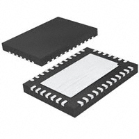
Software-Selectable Transceiver Supports: RS232, RS449, EIA530, EIA530-A, V.35, V.36, X.21 Operates from Single 5V Supply Separate Supply Pin for Digital Interface Works down to 3V On-Chip Cable Termination Complete DTE or DCE Port with LTC2845 Available in 38-Pin 5mm × 7mm QFN Package
APPLICATIO S
s s s
Data Networking CSU and DSU Data Routers
The LTC®2847 is a 3-driver/3-receiver multiprotocol transceiver with on-chip cable termination. When combined with the LTC2845, this chip set forms a complete softwareselectable DTE or DCE interface port that supports the RS232, RS449, EIA530, EIA530-A, V.35, V.36 and X.21 protocols. All necessary cable termination is provided inside the LTC2847. The VCC supplies the drivers, the receivers and an internal charge pump that requires only five space-saving surface mounted capacitors. The VIN supply drives the digital interface circuitry including the receiver output drivers. It can be tied to VCC or be powered off a lower supply (down to 3V) to interface with low voltage ASICs. The LTC2847 is available in a 0.8mm tall, 5mm × 7mm QFN package.
, LTC and LT are registered trademarks of Linear Technology Corporation.
TYPICAL APPLICATIO
Complete DTE or DCE Multiprotocol Serial Interface with DB-25 Connector
RL TM LL RI CTS DSR DCD DTR RTS RXD RXC TXC SCTE TXD
LTC2845 D5 R5 D4 R4 R3 R2 R1 D3 D2 D1 R3 R2
T
T
21
25
18
*
13 5
22 6
10 8
23 20 19 4
1
7
16
3
9
DB-25 CONNECTOR
2847 TA01
*OPTIONAL
sn2847 2847fs
U
LTC2847 D3 R1 D2 D1 T T T 17 12 15 11 24 14 2
U
U
RI (125)
CTS B
CTS A (106)
DSR B
DSR A (107)
RL (140)
TM (142)
LL A (141)
DTR B
DTR A (108)
RTS B
RTS A (105)
SHIELD (101)
SG (102)
DCD B
DCD A (109)
TXC B
TXC A (114)
SCTE B
SCTE A (113)
TXD B
TXD A (103)
RXD B
RXD A (104)
RXC B
RXC A (115)
1
�LTC2847
ABSOLUTE
(Note 1)
AXI U
RATI GS
PACKAGE/ORDER I FOR ATIO
TOP VIEW
C1+ C2 – C2 + C1– VEE VEE VEE
VCC Voltage.............................................. – 0.3V to 6.5V VIN Voltage .............................................. – 0.3V to 6.5V Input Voltage Transmitters ........................... – 0.3V to (VCC + 0.3V) Receivers ............................................... – 18V to 18V Logic Pins .............................. – 0.3V to (VCC + 0.3V) Output Voltage Transmitters ................. (VEE – 0.3V) to (VDD + 0.3V) Receivers ................................. – 0.3V to (VIN + 0.3V) VEE ........................................................ – 10V to 0.3V VDD ....................................................... – 0.3V to 10V Short-Circuit Duration Transmitter Output ..................................... Indefinite Receiver Output .......................................... Indefinite VEE .................................................................. 30 sec Operating Temperature Range LTC2847C ............................................... 0°C to 70°C LTC2847I ........................................... – 40°C to 85°C Storage Temperature Range ................ – 65°C to 150°C Lead Temperature (Soldering, 10 sec)................. 300°C
ORDER PART NUMBER
31 GND 30 GND 29 D1 A 28 D1 B 27 D2 A 26 D2 B 25 D3/R1 A 24 D3/R1 B 23 NC 22 NC 21 R2 A 20 R2 B
38 37 36 35 34 33 32 NC 1 VDD 2 NC 3 VCC 4 D1 5 D2 6 D3 7 R1 8 R2 9 R3 10 M0 11 M1 12 13 14 15 16 17 18 19
M2 R3 B R3 A NC DCE/DTE VIN NC
LTC2847CUHF LTC2847IUHF UHF PART MARKING 2847 2847I
UHF PACKAGE 38-LEAD (7mm × 5mm) PLASTIC QFN UNDERSIDE METAL INTERNALLY CONNECTED TO VEE (PCB CONNECTION OPTIONAL) TJMAX = 125°C, θJA = 34°C/W
Consult LTC Marketing for parts specified with wider operating temperature ranges.
ELECTRICAL CHARACTERISTICS
SYMBOL Supplies ICC VCC Supply Current (DCE Mode, All Digital Pins = GND or VIN) PARAMETER
The q denotes specifications which apply over the full operating temperature range, otherwise specifications are at TA = 25°C. VCC = 5V, VIN = 3.3V, unless otherwise noted (Notes 2, 3)
CONDITIONS RS530, RS530-A, X.21 Modes, No Load RS530, RS530-A, X.21 Modes, Full Load V.35 Mode V.28 Mode, No Load V.28 Mode, Full Load No-Cable Mode All Modes Except No-Cable Mode RS530, RS530-A, X.21 Modes, Full Load V.35 Mode, Full Load V.28 Mode, Full Load V.11 or V.28 Mode, No Load V.35 Mode V.28 Mode, with Load V.28 Mode, with Load, IDD = 10mA
q q q
MIN
TYP 14 100 126 20 35 300 405 410 625 150
MAX
UNITS mA mA mA mA mA µA µA mW mW mW V V V V
q q q q
130 170 75 900
IVIN PD
VIN Supply Current (DCE Mode, All Digital Pins = GND or VIN) Internal Power Dissipation (DCE Mode)
V+
Positive Charge Pump Output Voltage
8 7 8
9.3 8.0 8.7 6.5
sn2847 2847fs
2
U
W
U
U
WW
W
�LTC2847
ELECTRICAL CHARACTERISTICS
SYMBOL V– PARAMETER Negative Charge Pump Output Voltage
The q denotes specifications which apply over the full operating temperature range, otherwise specifications are at TA = 25°C. VCC = 5V, VIN = 3.3V, unless otherwise noted (Notes 2, 3)
CONDITIONS V.28 Mode, No Load V.28 Mode, Full Load V.35 Mode RS530, RS530-A, X.21 Modes, Full Load No-Cable Mode/Power-Off to Normal Operation D1, D2, D3, M0, M1, M2, DCE/DTE D1, D2, D3, M0, M1, M2, DCE/DTE D1, D2, D3 M0, M1, M2, DCE/DTE = GND M0, M1, M2, DCE/DTE = VIN IO = – 3mA IO = 1.6mA 0V ≤ VO ≤ VIN M0 = M1 = M2 = VIN, VO = GND M0 = M1 = M2 = VIN, VO = VIN RL = 1.95k (Figure 1) RL = 50Ω (Figure 1) RL = 50Ω (Figure 1) RL = 50Ω (Figure 1) RL = 50Ω (Figure 1) RL = 50Ω (Figure 1) VOUT = GND
VA and VB ≤ 0.25V, Power Off or q q q q q q q q q q q q q q q q q q
MIN – 7.5 – 5.5 – 4.5
TYP – 9.6 – 8.5 – 6.5 – 6.0 500 2
MAX
UNITS V V V V kHz ms V
fOSC tr VIH VIL IIN
Charge Pump Oscillator Frequency Charge Pump Rise Time Logic Input High Voltage Logic Input Low Voltage Logic Input Current
Logic Inputs and Outputs 2.0 0.8 – 30 2.7 – 75 3 0.2 –30 –85 0.4 ± 50 –160 ± 10 ±5 0.5VODO ±2 0.67VODO 0.2 3 0.2 ± 150 ±1 2 15 15 0 15 40 40 3 3 ± 100 25 65 65 12 ± 10 – 120 ± 10 V µA µA µA V V mA µA µA V V V V V V mA µA ns ns ns ns ns
VOH VOL IOSR IOZR V.11 Driver VODO VODL ∆VOD VOC ∆VOC ISS IOZ t r, t f t PLH t PHL ∆t t SKEW
Output High Voltage Output Low Voltage Output Short-Circuit Current Three-State Output Current
Open Circuit Differential Output Voltage Loaded Differential Output Voltage Change in Magnitude of Differential Output Voltage Common Mode Output Voltage Change in Magnitude of Common Mode Output Voltage Short-Circuit Current Output Leakage Current Rise or Fall Time Input to Output Rising Input to Output Falling Input to Output Difference, tPLH – tPHL Output to Output Skew
q q q q q
No-Cable Mode or Driver Disabled (Figures 2, 13) (Figures 2, 13) (Figures 2, 13) (Figures 2, 13) (Figures 2, 13)
sn2847 2847fs
3
�LTC2847
ELECTRICAL CHARACTERISTICS
SYMBOL VTH ∆VTH RIN t r, t f t PLH t PHL ∆t V.35 Driver VOD VOA, VOB VOC IOH IOL IOZ ROD ROC t r , tf t PLH t PHL ∆t t SKEW VTH ∆VTH RID RIC t r, t f tPLH tPHL ∆t V.28 Driver VO ISS ROZ SR t PLH t PHL Output Voltage Short-Circuit Current Power-Off Resistance Slew Rate Input to Output Input to Output Differential Output Voltage Single-Ended Output Voltage Transmitter Output Offset Transmitter Output High Current Transmitter Output Low Current Transmitter Output Leakage Current Transmitter Differential Mode Impedance Transmitter Common Mode Impedance Rise or Fall Time Input to Output Input to Output Input to Output Difference, tPLH – tPHL Output to Output Skew Differential Receiver Input Threshold Voltage Receiver Input Hysteresis Receiver Differential Mode Impedance Receiver Common Mode Impedance Rise or Fall Time Input to Output Input to Output Input to Output Difference, tPLH – tPHL PARAMETER Input Threshold Voltage Input Hysteresis Input Impedance Rise or Fall Time Input to Output Rising Input to Output Falling Input to Output Difference, tPLH – tPHL V.11 Receiver
The q denotes specifications which apply over the full operating temperature range, otherwise specifications are at TA = 25°C. VCC = 5V, VIN = 3.3V, unless otherwise noted (Notes 2, 3)
CONDITIONS – 7V ≤ VCM ≤ 7V – 7V ≤ VCM ≤ 7V –7V ≤ VCM ≤ 7V (Figure 3) CL = 50pF (Figures 4, 14) CL = 50pF (Figures 4, 14) CL = 50pF (Figures 4, 14) CL = 50pF (Figures 4, 14) Open Circuit, RL = 1.95k (Figure 5) With Load, – 4V ≤ VCM ≤ 4V (Figure 6) Open Circuit, RL = 1.95k (Figure 5) RL = 50Ω (Figure 5) VA, VB = 0V VA, VB = 0V
VA and VB ≤ 0.25V q q q q q q
MIN – 0.2
TYP
MAX 0.2
UNITS V mV Ω ns
15 100 103 15 50 50 0 4
40
90 90 25 ± 1.2 ± 0.66 ± 1.2 ± 0.6
ns ns ns V V V V mA mA µA Ω Ω ns ns ns ns ns
q
± 0.44
q q q q q q
± 0.55
–9 9 50 135
– 11 11 ±1 100 150 5 35 35 0 4
– 13 13 ± 100 150 165 65 65 16
– 2V ≤ VCM ≤ 2V (Figure 7) (Figures 8, 13) (Figures 8, 13) (Figures 8, 13) (Figures 8, 13) (Figures 8, 13) – 2V ≤ VCM ≤ 2V (Figure 9) – 2V ≤ VCM ≤ 2V (Figure 9) – 2V ≤ VCM ≤ 2V – 2V ≤ VCM ≤ 2V (Figure 10) CL = 50pF (Figures 4, 14) CL = 50pF (Figures 4, 14) CL = 50pF (Figures 4, 14) CL = 50pF (Figures 4, 14) Open Circuit RL = 3k (Figure 11) VOUT = GND – 2V < VO < 2V, Power Off or No-Cable Mode RL = 7k, CL = 0 (Figures 11, 15) RL = 3k, CL = 2500pF (Figures 11, 15) RL = 3k, CL = 2500pF (Figures 11, 15)
q q q q q q q q q
15 15
V.35 Receiver – 0.2 15 90 135 103 150 15 50 50 0 4 90 90 25 ± 10 ± 150 300 4 1.5 1.5 30 2.5 2.5 0.2 40 110 165 V mV Ω Ω ns ns ns ns V V mA Ω V/µs µs µs
sn2847 2847fs
q q q q q q q
±5
± 8.5
4
�LTC2847
ELECTRICAL CHARACTERISTICS
SYMBOL PARAMETER V.28 Receiver VTHL Input Low Threshold Voltage VTLH Input High Threshold Voltage ∆VTH Receiver Input Hysteresis RIN Receiver Input Impedance t r , tf Rise or Fall Time tPLH Input to Output tPHL Input to Output
The q denotes specifications which apply over the full operating temperature range, otherwise specifications are at TA = 25°C. VCC = 5V, VIN = 3.3V, unless otherwise noted (Notes 2, 3)
CONDITIONS (Figure 12) (Figure 12) (Figure 12) – 15V ≤ VA ≤ 15V CL = 50pF (Figures 12, 16) CL = 50pF (Figures 12, 16) CL = 50pF (Figures 12, 16)
q q q q q q
MIN
TYP
MAX 0.8
UNITS V V V kΩ ns ns ns
2 0 3
0.05 5 15 60 160
0.3 7 300 300
Note 1: Absolute Maximum Ratings are those values beyond which the life of the device may be impaired. Note 2: All currents into device pins are positive; all currents out of device are negative. All voltages are referenced to device ground unless otherwise specified.
Note 3: All typicals are given for VCC = 5V, VIN = 3.3V, CVCC = CVIN = 10µF, CVDD = 1µF, CVEE = 3.3µF and TA = 25°C.
TYPICAL PERFOR A CE CHARACTERISTICS
V.11 Mode ICC vs Data Rate
170 160 150 140
140
TA = 25°C
ICC (mA)
ICC (mA)
ICC (mA)
130 120 110 100 90 10 100 1000 10000
2846 G04
DATA RATE (kBd)
V.11 Mode ICC vs Temperature
110 105 100
ICC (mA)
ICC (mA) 128.0 127.5 127.0 126.5
95 90 85 80 –40 –20
125.5 125.0 124.5 124.0 123.5
ICC (mA)
40 20 60 0 TEMPERATURE (°C)
UW
80
2846 G07
V.35 Mode ICC vs Data Rate
150 145 TA = 25°C
V.28 Mode ICC vs Data Rate
60 55 50 45 40 35 30 TA = 25°C
135 130 125 120
10
100 1000 DATA RATE (kBd)
10000
2846 G05
10
20 40 DATA RATE (kBd)
60
80 100
2846 G06
V.35 Mode ICC vs Temperature
37.5 37.0 36.5 36.0 35.5 35.0 34.5 34.0
40 20 0 60 TEMPERATURE (°C) 80 100
V.28 Mode ICC vs Temperature
126.0
100
123.0 –40 –20
33.5 –40 – 20
0
60 40 20 TEMPERATURE (°C)
80
100
3846 G09
2846 G08
sn2847 2847fs
5
�LTC2847
PI FU CTIO S
NC (Pins 1,3,18,19,22,23): No Connect. VDD (Pin 2): Generated Positive Supply Voltage for V.28. Connect a 1µF capacitor to ground. VCC (Pin 4): Input Supply Pin. Input supply to charge pump and transceiver. 4.75V ≤ VCC ≤ 5.25V. Connect a 1µF capacitor to GND. D1 (Pin 5): TTL Level Driver 1 Input. D2 (Pin 6): TTL Level Driver 2 Input. D3 (Pin 7): TTL Level Driver 3 Input. R1 (Pin 8): CMOS Level Receiver 1 Output with Pull-Up to VIN when Three-Stated. R2 (Pin 9): CMOS Level Receiver 2 Output with Pull-Up to VIN when Three-Stated. R3 (Pin 10): CMOS Level Receiver 3 Output with Pull-Up to VIN when Three-Stated. M0 (Pin 11): TTL Level Mode Select Input 0 with Pull-Up to VIN. See Table 1. M1 (Pin 12): TTL Level Mode Select Input 1 with Pull-Up to VIN. See Table 1. VIN (Pin 13): Input Supply Pin. Input supply to digital interface including receiver output drivers. 3V ≤ VIN ≤ 5.25V. Connect to VCC (Pin 4) or to separate supply for lower receiver output swing. Connect a 1µF capacitor to GND. M2 (Pin 14): TTL Level Mode Select Input 2 with Pull-Up to VIN. See Table 1. DCE/DTE (Pin 15): TTL Level Mode Select Input with Pull-Up to VIN. See Table 1. R3 B (Pin 16): Receiver 3 Noninverting Input. R3 A (Pin 17): Receiver 3 Inverting Input. R2 B (Pin 20): Receiver 2 Noninverting Input. R2 A (Pin 21): Receiver 2 Inverting Input. D3/R1 B (Pin 24): Receiver 1 Noninverting Input and Driver 3 Noninverting Output. D3/R1 A (Pin 25): Receiver 1 Inverting Input and Driver 3 Inverting Output. D2 B (Pin 26): Driver 2 Noninverting Output. D2 A (Pin 27): Driver 2 Inverting Output. D1 B (Pin 28): Driver 1 Noninverting Output. D1 A (Pin 29): Driver 1 Inverting Output. GND (Pins 30,31): Transceiver Ground. VEE (Pins 32,33,36): Generated Negative Supply Voltage. Connect a 3.3µF capacitor to GND. Exposed pad can also be connected to VEE. C2 – (Pin 34): Capacitor C2 Negative Terminal. Connect a 1µF capacitor between C2 + and C2 –. C2 + (Pin 35): Capacitor C2 Positive Terminal. Connect a 1µF capacitor between C2 + and C2 – . C1– (Pin 37): Capacitor C1 Negative Terminal. Connect a 1µF capacitor between C1+ and C1–. C1+ (Pin 38): Capacitor C1 Positive Terminal. Connect a 1µF capacitor between C1+ and C1–.
6
U
U
U
sn2847 2847fs
�LTC2847
BLOCK DIAGRA
DCE/DTE 15 10k R1 8 R1 20k
W
CHARGE PUMP C1– 37 C1+ VDD 38 2 C1– C1+ VDD VCC VCC 4 50Ω S1 D1 5 D1 50Ω 28 D1 B 27 D2 A 50Ω S1 D2 6 D2 50Ω 26 D2 B D3 7 D3 10k 20k 6k S3 S2 125Ω 51.5Ω S1 25 D3/R1 A S2 125Ω S2 125Ω C2+ C2– VEE GND 30 31 GND 29 D1 A 32 33 35 C2+ 34 C2– 36 VEE 51.5Ω 24 D3/R1 B 21 R2 A 20k 10k R2 9 R2 10k 20k 17 R3 A 20k 10k R3 10 VIN 13 M0 11 M1 12 M2 14 MODE SELECTION LOGIC 20k R3 10k S3 S2 125Ω 51.5Ω 16 R3 B 6k 51.5Ω S3 S2 125Ω 51.5Ω 20 R2 B 6k 51.5Ω
2847 BD
sn2847 2847fs
7
�LTC2847
TEST CIRCUITS
D B A VOD RL
2847 F01
RL
D
VOC
B A
RL 100Ω
CL 100pF CL 100pF
2847 F02
Figure 1. V.11 Driver DC Test Circuit
IB B R IA VCM = ± 7V
Figure 2. V.11 Driver AC Test Circuit
B A
R CL
2847 F04
+ –
A 2(VB – VA) RIN = IB – IA 2847 F03
Figure 3. Input Impedance Test Circuit
VOB VOB
Figure 4. V.11, V.35 Receiver AC Test Circuit
125Ω
50Ω VOD 50Ω
RL
125Ω VOC
50Ω 50Ω
50Ω 50Ω
125Ω VCM
125Ω
50Ω 50Ω
RL
+ –
2847 F07
VCM = ± 2V
2847 F05
2847 F06
VOA
VOA
Figure 5. V.35 Driver Open-Circuit Test
Figure 6. V.35 Driver Test Circuit
Figure 7. V.35 Driver Common Mode Impedance Test Circuit
125Ω
50Ω 50Ω
50Ω
51.5Ω 125Ω 125Ω
50Ω
VTH VCM
+ – + –
2847 F09
VCM = ± 2V
+ –
51.5Ω
2847 F08
2847 F10
Figure 8. V.35 Driver AC Test Circuit
Figure 9. V.35 Receiver DC Test Circuit
Figure 10. Receiver Common Mode Impedance Test Circuit
R CL
2847 F12
D
A CL
2847 F11
A RL VA
Figure 11. V.28 Driver Test Circuit
Figure 12. V.28 Receiver Test Circuit
sn2847 2847fs
8
�LTC2847
ODE SELECTIO
Table 1
Mode Name
(Note 1) (Note 1)
M2 M1 M0 DCE/ D1,2 D3 DTE A
Not Used (Default V.11) 0 RS530A RS530 X.21 V.35 RS449/V.36 V.28/RS232 No Cable 0 0 0 1 1 1 1
0 0 1 1 0 0 1 1 0 0 1 1 0 0 1 1
0 1 0 1 0 1 0 1 0 1 0 1 0 1 0 1
0 0 0 0 0 0 0 0 1 1 1 1 1 1 1 1
TTL TTL TTL TTL TTL TTL TTL X
Not Used (Default V.11) 0 RS530A RS530 X.21 V.35 RS449/V.36 V.28/RS232 No Cable 0 0 0 1 1 1 1
TTL TTL V.11 V.11 V.11 V.11 V.11 V.11 30k 30k V.11 V.11 V.11 V.11 TTL TTL V.11 V.11 V.11 V.11 V.11 V.11 30k 30k V.11 V.11 V.11 V.11 TTL TTL V.11 V.11 V.11 V.11 V.11 V.11 30k 30k V.11 V.11 V.11 V.11 TTL TTL V.11 V.11 V.11 V.11 V.11 V.11 30k 30k V.11 V.11 V.11 V.11 TTL TTL V.35 V.35 V.35 V.35 V.35 V.35 30k 30k V.35 V.35 V.35 V.35 TTL TTL V.11 V.11 V.11 V.11 V.11 V.11 30k 30k V.11 V.11 V.11 V.11 TTL TTL V.28 X X Z Z Z V.28 Z Z Z V.28 Z Z Z 30k 30k V.28 30k V.28 30k 30k 30k 30k 30k 30k 30k
Note 1: Driver inputs are TTL level compatible. Note 2: Unused receiver inputs are terminated with 30k to ground. In addition, R2 and R3 are always terminated by a 103Ω differential impedence (see Block Diagram on page 7). Note 3: Receiver Outputs are CMOS level compatible and have a weak pull up to VIN when Z.
SWITCHI G TI E WAVEFOR S
3V D 0V VO B–A –VO A VO B t SKEW t SKEW
2847 F13
1.5V t PLH 50% tr 90% 10%
1/2 VO
Figure 13. V.11, V.35 Driver Propagation Delays
VOD2 B–A –VOD2 VOH R VOL 0V t PLH 1.65V OUTPUT f = 1MHz : t r ≤ 10ns : t f ≤ 10ns INPUT 0V t PHL 1.65V
2847 F14
Figure 14. V.11, V.35 Receiver Propagation Delays
sn2847 2847fs
W
U
D1 B A D2 B A Z Z Z Z Z Z Z Z D3 B Z Z Z Z Z Z Z Z A R1
(Note 2)
W
U
W
R2
(Note 2)
R3
(Note 2)
R1
(Note 3)
R2,R3
(Note 3)
VDD (Note 4)
VEE (Note 5)
B
A
B
A
B CMOS CMOS CMOS CMOS CMOS CMOS CMOS Z CMOS CMOS CMOS CMOS CMOS CMOS CMOS Z 9.3V 9.3V 9.3V 9.3V 8V 9.3V 8.7V 4.7V 9.3V 9.3V 9.3V 9.3V 8V 9.3V 8.7V 4.7V –6V –6V –6V –6V –6.5V –6V –8.5V 0.3V –6V –6V –6V –6V –6.5V –6V –8.5V 0.3V
X X X X X X X X
V.11 V.11 V.11 V.11 V.11 V.11 V.11 V.11 V.11 V.11 V.11 V.11 V.11 V.11 V.11 V.11 V.35 V.35 V.35 V.35 V.11 V.11 V.11 V.11 V.28 Z Z Z V.28 Z Z Z
V.11 V.11 V.11 V.11 V.11 V.11 CMOS V.11 V.11 V.11 V.11 V.11 V.11 CMOS V.11 V.11 V.11 V.11 V.11 V.11 CMOS V.11 V.11 V.11 V.11 V.11 V.11 CMOS V.35 V.35 V.35 V.35 V.35 V.35 CMOS V.11 V.11 V.11 V.11 V.11 V.11 CMOS V.28 30k V.28 30k V.28 30k CMOS 30k 30k 30k 30k 30k 30k Z Z Z Z Z Z Z Z Z
Note 4: VDD values shown are typical values for VCC = 5V, VIN = 3.3V and TA = 25°C with LTC2847 under full load for each mode. Note 5: VEE values shown are typical values for VCC = 5V, VIN = 3.3V and TA = 25°C with LTC2847 under full load for each mode.
f = 1MHz : t r ≤ 10ns : t f ≤ 10ns
1.5V t PHL 90% tf 50%
10%
9
�LTC2847
SWITCHI G TI E WAVEFOR S
3V D 0V VO A –VO tf 1.5V t PHL 3V 0V SR = 6V tf –3V 1.5V t PLH 0V –3V tr 3V SR = 6V tr
2847 F15
Figure 15. V.28 Driver Propagation Delays
VIH A VIL VOH R VOL 1.5V t PHL 1.65V 1.5V t PLH 1.65V
2847 F16
Figure 16. V.28 Receiver Propagation Delays
APPLICATIO S I FOR ATIO
Overview
The LTC2847 consists of a charge pump and a 3-driver/ 3-receiver transceiver. The 5V VCC input powers the charge pump and transceiver. The charge pump generates the VDD and VEE supplies. The LTC2847’s VDD and VEE supplies can be used to power a companion chip like the LTC2845. The VIN input powers the digital interface including the receiver output drivers. Having a separate pin to power the digital interface allows the flexibility of controlling the receiver output swing to interface with 5V or 3.3V logic. The LTC2847 and LTC2845 form a complete softwareselectable DTE or DCE interface port that supports the RS232, RS449, EIA530, EIA530-A, V.35, V.36 and X.21 protocols. Cable termination is provided on-chip, eliminating the need for discrete termination designs. A complete DCE-to-DTE interface operating in EIA530 mode is shown in Figure 17. The LTC2847 half of each port is used to generate and appropriately terminate the clock and data signals. The LTC2845 is used to generate the control signals along with LL (local loopback),
10
W
U
W
UU
W
U
RL (Remote Loop-Back), TM (Test Mode) and RI (Ring Indicate). Mode Selection The interface protocol is selected using the mode select pins M0, M1 and M2 (see Table 1). For example, if the port is configured as a V.35 interface, the mode selection pins should be M2 = 1, M1 = 0, M0 = 0. For the control signals, the drivers and receivers will operate in V.28 (RS232) electrical mode. For the clock and data signals, the drivers and receivers will operate in V.35 electrical mode. The DCE/DTE pin will configure the port for DCE mode when high, and DTE when low. The interface protocol may be selected simply by plugging the appropriate interface cable into the connector. The mode pins are routed to the connector and are left unconnected (1) or wired to ground (0) in the cable as shown in Figure 18. The internal pull-up current sources will ensure a binary 1 when a pin is left unconnected. The mode selection may also be accomplished by using jumpers to connect the mode pins to ground or VIN.
sn2847 2847fs
�LTC2847
APPLICATIO S I FOR ATIO
DTE
SERIAL CONTROLLER TXD D1 LTC2847
SCTE
D2
D3
TXC
R1
103Ω
RXC
R2
103Ω
RXD
R3
103Ω
LTC2845 RTS D1 RTS
DTR
D2
D3
DCD
R1
DSR
R2
CTS
R3
LL TM RI RL
D4 R4 R5 D5
Figure 17. Complete Multiprotocol Interface in EIA530 Mode
When the cable is removed, leaving all mode pins unconnected, the LTC2847/LTC2845 will enter no-cable mode. In this mode the LTC2847/LTC2845 supply current drops to less than 1000µA and the LTC2847/LTC2845 driver outputs are forced into a high impedance state. At the same time, the R2 and R3 receivers of the LTC2847 are differentially terminated with 103Ω and the other receiv-
U
DCE
LTC2847 TXD 103Ω R3 SERIAL CONTROLLER TXD SCTE 103Ω R2 SCTE R1 TXC D3 TXC RXC D2 RXC RXD D1 RXD LTC2845 R3 RTS DTR R2 DTR R1 DCD D3 DCD DSR D2 DSR CTS LL TM RI RL D1 CTS R4 D4 D5 R5 LL TM RI RL
2847 F17
W
UU
ers on the LTC2847 and LTC2845 are terminated with 30kΩ to ground. Cable Termination Traditional implementations used expensive relays to switch resistors or required the user to change termination modules every time a new interface standard was
sn2847 2847fs
11
�LTC2847
APPLICATIO S I FOR ATIO
(DATA) M0 LTC2847 M1 M2 DCE/DTE
DCE/DTE M2 LTC2845 M1 M0 (DATA)
2847 F18
Figure 18. Single Port DCE V.35 Mode Selection in the Cable
selected. Switching the terminations with FETs is difficult because the FETs must remain off when the signal voltage is beyond the supply voltage. Alternatively, custom cables may contain termination in the cable head or route signals to various terminations on the board. The LTC2847/LTC2845 chip set solves the cable termination switching problem by automatically providing the appropriate termination and switching on-chip for the V.10 (RS423), V.11 (RS422), V.28 (RS232) and V.35 electrical protocols. V.10 (RS423) Interface All V.10 drivers and receivers necessary for the RS449, EIA530, EIA530-A, V.36 and X.21 protocols are implemented on the LTC2845. A typical V.10 unbalanced interface is shown in Figure 19. A V.10 single-ended generator with output A and ground C is connected to a differential receiver with input A' connected to A, and ground C' connected via the signal return to ground C. Usually, no cable termination is required for V.10 interfaces, but the receiver inputs must be compliant with the impedance curve shown in Figure 20. The V.10 receiver configuration in the LTC2845 is shown in Figure 21. In V.10 mode, switch S3 inside the LTC2845 is turned off. The noninverting input is disconnected inside the LTC2845 receivers and connected to ground.
12
U
CONNECTOR NC NC CABLE
GENERATOR BALANCED INTERCONNECTING CABLE LOAD CABLE TERMINATION A A' RECEIVER C C'
2847 F19
W
UU
Figure 19. Typical V.10 Interface
IZ
3.25mA
–10V
–3V VZ 3V 10V
–3.25mA
2847 F20
Figure 20. V.10 Receiver Input Impedance
sn2847 2847fs
�LTC2847
APPLICATIO S I FOR ATIO
A' A R8 6k S3 R5 20k R6 10k RECEIVER LTC2845
B' C'
B GND
R4 20k
R7 10k
2847 F21
Figure 21. V.10 Receiver Configuration
BALANCED INTERCONNECTING CABLE
GENERATOR
LOAD CABLE TERMINATION RECEIVER
A
A' 100Ω MIN
B C
B' C'
Figure 22. Typical V.11 Interface
The cable termination is then the 30k input impedance to ground of the LTC2845 V.10 receiver. V.11 (RS422) Interface A typical V.11 balanced interface is shown in Figure 22. A V.11 differential generator with outputs A and B and ground C is connected to a differential receiver with input A' connected to A, input B' connected to B, and ground C' connected via the signal return to ground C. The V.11 interface has a differential termination at the receiver end that has a minimum value of 100Ω. The termination resistor is optional in the V.11 specification, but for the high speed clock and data lines, the termination is essential to prevent reflections from corrupting the data. The receiver inputs must also be compliant with the impedance curve shown in Figure 20. In V.11 mode, all switches are off except S1 of the LTC2847’s receivers which connects a 103Ω differential
there is no switch S1 in receivers R2 and R3. However, for simplicity, all termination networks on the LTC2847 can be treated identically if it is assumed that an S1 switch exists and is always closed on the R2 and R3 receivers.
1Actually,
U
A' R1 51.5Ω S1 S2 R2 51.5Ω R8 6k S3 R5 20k R6 10k R3 124Ω RECEIVER LTC2847 B' C' R4 20k R7 10k GND
2847 F23
W
UU
Figure 23. V.11 Receiver Configuration
termination impedance to the cable as shown in Figure 231. The LTC2845 only handles control signals, so no termination other than its V.11 receivers’ 30k input impedance is necessary. V.28 (RS232) Interface A typical V.28 unbalanced interface is shown in Figure 24. A V.28 single-ended generator with output A and ground C is connected to a single-ended receiver with input A' connected to A and ground C' connected via the signal return to ground C.
GENERATOR BALANCED INTERCONNECTING CABLE LOAD CABLE TERMINATION A A' RECEIVER
2847 F22
C
C'
2847 F24
Figure 24. Typical V.28 Interface
A' R1 51.5Ω S1 S2 R2 51.5Ω R8 6k S3 R5 20k R6 10k RECEIVER LTC2847
R3 124Ω
B'
R4 20k
R7 10k
C'
GND
2847 F25
Figure 25. V.28 Receiver Configuration
sn2847 2847fs
13
�LTC2847
APPLICATIO S I FOR ATIO
In V.28 mode, S3 is closed inside the LTC2847/LTC2845 which connects a 6k (R8) impedance to ground in parallel with 20k (R5) plus 10k (R6) for a combined impedance of 5k as shown in Figure 25. Proper termination is only provided when the B input of the receivers is floating, since S1 of the LTC2847’s R2 and R3 receivers remains on in V.28 mode1. The noninverting input is disconnected inside the LTC2847/LTC2845 receiver and connected to a TTL level reference voltage to give a 1.4V receiver trip point. V.35 Interface A typical V.35 balanced interface is shown in Figure 26. A V.35 differential generator with outputs A and B and ground C is connected to a differential receiver with input A' connected to A, input B' connected to B, and ground C' connected via the signal return to ground C. The V.35 interface requires a T or delta network termination at the receiver end and the generator end. The receiver differential impedance measured at the connector must be 100Ω ±10Ω, and the impedance between shorted terminals (A' and B') and ground (C') must be 150Ω ±15Ω.
GENERATOR BALANCED INTERCONNECTING CABLE LOAD CABLE TERMINATION A 50Ω 125Ω A' 125Ω 50Ω RECEIVER
50Ω B C B' C'
50Ω
Figure 26. Typical V.35 Interface
A' R1 51.5Ω S1 S2 R2 51.5Ω R8 6k S3 R5 20k R6 10k R3 124Ω RECEIVER LTC2847
B'
5V
VCC C5 1µF
GND
C'
GND
2847 F27
Figure 27. V.35 Receiver Configuration
Figure 28. Charge Pump
sn2847 2847fs
14
+
R4 20k
R7 10k
U
In V.35 mode, both switches S1 and S2 inside the LTC2847 are on, connecting a T network impedance as shown in Figure 27. The 30k input impedance of the receiver is placed in parallel with the T network termination, but does not affect the overall input impedance significantly. The generator differential impedance must be 50Ω to 150Ω and the impedance between shorted terminals (A and B) and ground (C) must be 150Ω ±15Ω. No-Cable Mode The no-cable mode (M0 = M1 = M2 = 1) is intended for the case when the cable is disconnected from the connector. The charge pump, bias circuitry, drivers and receivers are turned off, the driver outputs are forced into a high impedance state, and the VCC supply current to the transceiver drops to less than 300µA while its VIN supply current drops to less than 10µA. Note that the LTC2847’s R2 and R3 receivers continue to be terminated by a 103Ω differential impedance. Charge Pump The LTC2847 uses an internal capacitive charge pump to generate VDD and VEE as shown in Figure 28. A voltage doubler generates about 8V on VDD and a voltage inverter generates about – 7.5V on VEE. Four 1µF surface mounted tantalum or ceramic capacitors are required for C1, C2, C3 and C5. The VEE capacitor C4 should be a minimum of 3.3µF. All capacitors are 16V and should be placed as close as possible to the LTC2847 to reduce EMI. Receiver Fail-Safe All LTC2847/LTC2845 receivers feature fail-safe operation in all modes. If the receiver inputs are left floating or are shorted together by a termination resistor, the receiver output will always be forced to a logic high.
C3 1µF C1 1µF VDD C1+ LTC2847 C1– VEE C4 3.3µF C2 + C2 – C2 1µF
2847 F26 2847 F28
W
UU
�LTC2847
TYPICAL APPLICATIO S
DTE vs DCE Operation The DCE/DTE pin acts as an enable for Driver 3/Receiver 1 in the LTC2847, and Driver 3/Receiver 1 in the LTC2845. The LTC2847/LTC2845 can be configured for either DTE or DCE operation in one of two ways: a dedicated DTE or DCE port with a connector of appropriate gender or a port with one connector that can be configured for DTE or DCE operation by rerouting the signals to the LTC2847/LTC2845 using a dedicated DTE cable or dedicated DCE cable. A dedicated DTE port using a DB-25 male connector is shown in Figure 29. The interface mode is selected by logic outputs from the controller or from jumpers to either VIN or GND on the mode select pins. A dedicated DCE port using a DB-25 female connector is shown in Figure 30. A port with one DB-25 connector, that can be configured for either DTE or DCE operation is shown in Figure 31. The configuration requires separate cables for proper signal routing in DTE or DCE operation. For example, in DTE mode, the TXD signal is routed to Pins 2 and 14 via the LTC2847’s Driver 1. In DCE mode, Driver 1 now routes the RXD signal to Pins 2 and 14. Power Dissipation Calculations The LTC2847 takes in 5V VCC. VDD and VEE are in turn produced from VCC with an internal charge pump at approximately 80% and 70% efficiency respectively. Current drawn internally from VDD or VEE translates directly into a higher ICC. The LTC2847 dissipates power according to the equation: PDISS(2847) = VCC • ICC – ND • PRT + NR • PRT (1) PRT refers to the power dissipated by each driver in a receiver termination on the far end of the cable while ND is the number of drivers. Conversely, current from the far end drivers dissipate power NR • PRT in the internal receiver termination where NR is the number of receivers. LTC2847 Power Dissipation Consider an LTC2847 in X.21, DCE mode (three V.11 drivers and two V.11 receivers). From the Electrical Characteristics Table, ICC at no load = 14mA, ICC at full load = 100mA. Each receiver termination is 100Ω (RRT) and current going into each receiver termination = (100mA – 14mA)/3 = 28.7mA (IRT). PRT = (IRT)2 • RRT (2) From Equation (2), PRT = 82.4mW and from Equation (1), DC power dissipation PDISS(2847) = 5V • 100mA – 3 • 82.4mW + 2 • 82.4mW = 418mW. Consider the above example running at a baud rate of 10MBd. From the Typical Characteristic for “V.11 Mode ICC vs Data Rate,” the ICC at 10MBd is 160mA. ICC increases with baud rate due to driver transient dissipation. From Equation (1), AC power dissipation PDISS(2847) = 5V • 160mA –3 • 82.4mW + 2 • 82.4mW = 718mW. LTC2845 Power Dissipation If a LTC2845 is used to form a complete DCE port with the LTC2847, it will be running in the X.21 mode (three V.11 drivers and two V.10 drivers, two V.11 receivers and two V.10 receivers, all with internal 30k termination). In addition to VCC, it uses the VDD and VEE outputs from the LTC2847. Negligible power is dissipated in the large internal receiver termination of the LTC2845 so the NR • PRT term of Equation (1) can be omitted. Thus Equation (1) is modified as follows: PDISS(2845) = (VCC • ICC) + (VDD • IDD) + (VEE • IEE) – ND • PRT (3)
U
Since power is drawn from the supplies of the LTC2847 (VDD and VEE) at less than 100% efficiency, the LTC2847 dissipates extra power to source PDISS(2845) and PRT : PDISS1(2847) = 125% • (VDD • IDD) + 143% • (4) (VEE • IEE) – PDISS(2845) – ND • PRT = 25% • (VDD • IDD) + 43% • (VEE • IEE) From the LTC2845 Electrical Characteristics Table, for VCC = 5V, VDD = 8V and VEE = – 5.5V:
ICC at no load ICC at full load with all drivers high IEE at no load IEE at full load with both V.10 drivers low IDD at no load IDD at full load 2.7mA 110mA 2mA 23mA 0.3mA 0.3mA
sn2847 2847fs
15
�LTC2847
TYPICAL APPLICATIO S
C3 1µF VCC 5V C5 1µF TXD LTC2847 D1 T C2 1µF C1 1µF CHARGE PUMP C4 3.3µF
SCTE
D2
T
D3
T 15 TXC A (114) TXC B RXC A (115) RXC B RXD A (104) RXD B SG SHIELD
TXC
R1
RXC
R2
T
RXD M0 M1 M2
R3
T
DCE/DTE
C7 1µF
VCC C8 1µF RTS VDD D1
VEE GND
DTR
D2
D3 LTC2845 DCD R1 R2 8 10 6 DSR 22 5 CTS R3 13 18 *
LL RI
R4 D4
TM RL M0 M1 M2 M0 M1 M2
R5 D5 VIN D4ENB R4EN NC VIN 3.3V C10 1µF *OPTIONAL
DCE/DTE
Figure 29. Controller-Selectable Multiprotocol DTE Port with DB-25 Connector
sn2847 2847fs
16
+
U
2 14 24 11
TXD A (103) TXD B SCTE A (113) SCTE B
12 17 9 3 16 7 VIN 3.3V C6 1µF C9 1µF 4 19 20 23 1
DB-25 MALE CONNECTOR
RTS A (105) RTS B DTR A (108) DTR B
DCD A (109) DCD B DSR A (107) DSR B CTS A (106) CTS B LL (141) RI (125)
25 21
TM (142) RL (140)
2847 F29
�LTC2847
TYPICAL APPLICATIO S
C3 1µF VCC 5V C5 1µF RXD LTC2847 D1 T C2 1µF C1 1µF CHARGE PUMP C4 3.3µF
RXC
D2
T
D3
T 15 TXC A (114) TXC B SCTE A (113) SCTE B TXD A (103) TXD B SGND (102) SHIELD (101) DB-25 FEMALE CONNECTOR 5
TXC
R1
SCTE
R2
T
TXD M0 M1 M2 NC
R3
T
DCE/DTE
C7 1µF
VCC C8 1µF CTS VDD D1
VEE GND
DSR
D2
D3 LTC2845 DCD R1 R2 8 10 20 DTR 23 4 RTS R3 19 * 18
RI LL
R4 D4
RL TM M0 M1 M2 NC M0 M1 M2
R5 D5 VIN D4ENB R4EN VIN 3.3V
DCE/DTE
Figure 30. Controller-Selectable DCE Port with DB-25 Connector
sn2847 2847fs
+
U
2 14 24 11
RXD A (104) RXD B RXC A (115) RXC B
12 24 11 2 14 7 VIN 3.3V C6 1µF C9 1µF 13 6 22 1
CTS A (106) CTS B DSR A (107) DSR B
DCD A (109) DCD B DTR A (108) DTR B RTS A (105) RTS B RI (125) LL (141)
21 25 *OPTIONAL
RL (140) TM 9142)
C10 1µF NC
2847 F30
17
�LTC2847
TYPICAL APPLICATIO S
C3 1µF VCC 5V C5 1µF DTE_TXD/DCE_RXD LTC2847 D1 T C2 1µF C1 1µ F CHARGE PUMP C4 3.3µF DTE TXD A TXD B SCTE A SCTE B DCE RXD A RXD B RXC A RXC B
DTE_SCTE/DCE_RXC
D2
T
D3 DTE_TXC/DCE_TXC
T 15 R1 12 17 TXC A TXC B RXC A RXC B RXD A RXD B SG SHIELD DB-25 CONNECTOR 4 TXC A TXC B SCTE A SCTE B TXD A TXD B
DTE_RXC/DCE_SCTE
R2
T
DTE_RXD/DCE_TXD M0 M1 M2
R3
T
DCE/DTE
C7 1µF
VCC C8 1µF DTE_RTS/DCE_CTS VDD D1
VEE GND
DTE_DTR/DCE_DSR
D2
D3 LTC2845 DTE_DCD/DCE_DCD R1 R2 8 10 6 DTE_DSR/DCE_DTR 22 5 DTE_CTS/DCE_RTS R3 13 18 *
DTE_LL/DCE_RI DTE_RI/DCE_LL
D4 R4
DTE_TM/DCE_RL DTE_RL/DCE_TM M0 M1 M2 DCE/DTE M0 M1 M2
R5 D5 VIN D4ENB R4EN NC 15 C10 1µF VIN 3.3V
DCE/DTE
Figure 31. Controller-Selectable Multiprotocol DTE/DCE Port with DB-25 Connector
sn2847 2847fs
18
+
U
2 14 24 11
9 3 16 7 VIN 3.3V C6 1µF C9 1µF 19 20 23 1
RTS A RTS B DTR A DTR B
CTS A CTS B DSR A DSR B
DCD A DCD B DSR A DSR B CTS A CTS B LL RI
DCD A DCD B DTR A DTR B RTS A RTS B LL RI
25 21 *OPTIONAL
TM RL
TM RL
2847 F31
�LTC2847
PACKAGE DESCRIPTIO
5.50 ± 0.05 (2 SIDES) 4.10 ± 0.05 (2 SIDES) 3.20 ± 0.05 (2 SIDES)
5.00 ± 0.10 (2 SIDES)
PIN 1 TOP MARK (SEE NOTE 6)
7.00 ± 0.10 (2 SIDES)
0.75 ± 0.05
NOTE: 1. DRAWING CONFORMS TO JEDEC PACKAGE OUTLINE M0-220 VARIATION WHKD 2. DRAWING NOT TO SCALE 3. ALL DIMENSIONS ARE IN MILLIMETERS
Information furnished by Linear Technology Corporation is believed to be accurate and reliable. However, no responsibility is assumed for its use. Linear Technology Corporation makes no representation that the interconnection of its circuits as described herein will not infringe on existing patent rights.
U
UHF Package 38-Lead Plastic QFN (5mm × 7mm)
(Reference LTC DWG # 05-08-1701)
0.70 ± 0.05 PACKAGE OUTLINE 0.25 ± 0.05 0.50 BSC 5.20 ± 0.05 (2 SIDES) 6.10 ± 0.05 (2 SIDES) 7.50 ± 0.05 (2 SIDES) RECOMMENDED SOLDER PAD LAYOUT 0.75 ± 0.05 0.00 – 0.05 3.15 ± 0.10 (2 SIDES) 0.435 0.18 0.18 37 38 1 2 0.23 5.15 ± 0.10 (2 SIDES) 0.40 ± 0.10 0.200 REF 0.25 ± 0.05 0.200 REF 0.00 – 0.05 0.50 BSC R = 0.115 TYP
(UH) QFN 0303
BOTTOM VIEW—EXPOSED PAD
4. DIMENSIONS OF EXPOSED PAD ON BOTTOM OF PACKAGE DO NOT INCLUDE MOLD FLASH. MOLD FLASH, IF PRESENT, SHALL NOT EXCEED 0.20mm ON ANY SIDE 5. EXPOSED PAD SHALL BE SOLDER PLATED 6. SHADED AREA IS ONLY A REFERENCE FOR PIN 1 LOCATION ON THE TOP AND BOTTOM OF PACKAGE
sn2847 2847fs
19
�LTC2847
TYPICAL APPLICATIO S
The V.11 drivers are driven between VCC and GND while the V.10 drivers are driven between VCC and VEE. Assume that the V.11 driver outputs are high and V.10 driver outputs low. Current going into each 100Ω V.11 receiver termination = (110mA – 2.7mA) – 23mA/3 = 28.1mA. Current going into each 450Ω V.10 receiver termination = 23mA – 2mA/2 = 10.5mA. From Equation (2), V.11 PRT = 79mW and V.10 PRT = 49.6mW. From Equation (3), PDISS(2845) = 5V • (110mA – 23mA) + (8V • 0.3mA) + 5.5V • 23mA – 3 • 79mW – 2 • 49.6mW = 228mW. Since the LTC2845 runs slow control signals, the AC power dissipation can be assumed to be equal to the DC power dissipation. The extra power dissipated in the LTC2847 due to LTC2845 is given by Equation(4), PDISS1(2847) = 25% • (8V • 0.3mA) + 43% • (5.5V • 23mA) = 55mW. So for an X.21 DCE port running at 10MBd, the LTC2847 dissipates approximately 718mW + 55mW = 773mW while the LTC2845 dissipates 228mW.
RELATED PARTS
PART NUMBER
LTC1321 LTC1334 LTC1343 LTC1344A LTC1345 LTC1346A LTC1543 LTC1544 LTC1545 LTC1546 LTC2844 LTC2845 LTC2846
DESCRIPTION
Dual RS232/RS485 Transceiver Single 5V RS232/RS485 Multiprotocol Transceiver Software-Selectable Multiprotocol Transceiver Software-Selectable Cable Terminator Single Supply V.35 Transceiver Dual Supply V.35 Transceiver Software-Selectable Multiprotocol Transceiver Software-Selectable Multiprotocol Transceiver Software-Selectable Multiprotocol Transceiver Software-Selectable Multiprotocol Transceiver 3.3V Software-Selectable Multiprotocol Transceiver 3.3V Software-Selectable Multiprotocol Transceiver 3.3V Software-Selectable Multiprotocol Transceiver
20
Linear Technology Corporation
1630 McCarthy Blvd., Milpitas, CA 95035-7417
(408) 432-1900 q FAX: (408) 434-0507
q
U
COMMENTS
Two RS232 Driver/Receiver Pairs or Two RS485 Driver/Receiver Pairs Two RS232 Driver/Receiver or Four RS232 Driver/Receiver Pairs 4-Driver/4-Receiver for Data and Clock Signals Perfect for Terminating the LTC1543 (Not Needed with LTC1546) 3-Driver/3-Receiver for Data and Clock Signals 3-Driver/3-Receiver for Data and Clock Signals Terminated with LTC1344A for Data and Clock Signals, Companion to LTC1544 or LTC1545 for Control Signals Companion to LTC1546 or LTC1543 for Control Signals Including LL 5-Driver/5-Receiver Companion to LTC1546 or LTC1543 for Control Signals Including LL, TM and RL 3-Driver/3-Receiver with Termination for Data and Clock Signals Companion to LTC2846 for Control Signals Including LL 5-Driver/5-Receiver Companion to LTC2846 or LTC2847 for Control Signals Including LL, TM and RL 3.3V Supply, 3-Driver/3-Receiver with Termination for Data and Clock Signals, Generates the Required 5V and ±8V Supplies for LTC2846 Companion Parts
sn2847 2847fs LT/TP 0603 1K • PRINTED IN USA
www.linear.com
© LINEAR TECHNOLOGY CORPORATION 2003
�