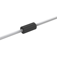
Teccor® brand Protection Thyristors
Axial Leaded
DO-41 Series SIDACtor® Device
Description This DO-41 plastic package provides a through-hole version of the SIDACtor® devices. This axial leaded device is ideal for Customer Premises Equipment (CPE) such as telephones, answering machines, modems, and fax interfaces. The DO-41 package series can also be used for overvoltage protection for applications such as T1/E1/J1 trunk cards when the appropriate overcurrent protection is included.
Features Agency Approvals
Agency Agency File Number E133083
• RoHS compliant • Bidirectional transient voltage protection • Axial lead through-hole component • Teccor brand SIDACtor technology
Protection solution to meet • YD/T 950 • YD/T 993 • YD/T 1082 • GR 1089 Intra-building • IEC 61000-4-5 • ITU K.20/21 Basic Level • TIA-968-A Type B Surges
Electrical Characteristics
VDRM @lDRM=5µA Volts Min P1100THLRP P1300THLRP P1500THLRP P1800THLRP P2300THLRP P2600THLRP P3100THLRP P3500THLRP P11H P13H P15H P18H P23H P26H P31H P35H 90 120 140 170 190 220 275 320 VS @100V/µs Volts Max 130 160 180 220 260 300 350 400 IH IS IT Amps Max 1.0 1.0 1.0 1.0 1.0 1.0 1.0 1.0 VT @IT=1 amp Volts Max 5 5 5 5 5 5 5 5 Capacitance @1MHz, 2V bias pF Typical 60 40 40 40 30 30 30 30
Part Number
Marking
mAmps mAmps Min 150 150 150 150 150 150 150 150 Max 800 800 800 800 800 800 800 800
• All measurements are made at an ambient temperature of 25°C. • Listed SIDACtor devices are bidirectional. All electrical parameters and surge ratings apply to forward and reverse polarities.
DO-41 Series Specifications are subject to change without notice.
1 Telecom Design Guide
www.littelfuse.com ©2006 Littelfuse
�Teccor® brand Protection Thyristors
Axial Leaded
Surge Ratings
IPP Series
5x320 µs Amps Min 10x1000 µs Amps Min 35
H
25
• IPP applies to -40°C through +85°C temperature range. • IPP is a repetitive surge rating and is guaranteed for the life of the product.
V-I Characteristics
+I
tr x td Pulse Waveform
IPP – Peak Pulse Current – %IPP
IT IS IH -V IDRM VT VDRM VS +V
100
Peak Value
tr = rise time to peak value td = decay time to half value
Waveform = tr x td 50
Half Value
0 0
tr
td
-I
t – Time (µs)
Normalized VS Change Versus Junction Temperature
Normalized DC Holding Current Versus Case Temperature
Percent of VS Change – %
IH (TC = 25 ˚C)
14 12 10 8 6 4 2 -4 -6 -8 -40 -20 0 20 40 60 80 100 120 140 160 0
2.0 1.8 1.6 1.4 1.2 1.0 0.8 0.6 0.4 -40 -20 0
IH
25 ˚C
25 ˚C
Ratio of
Junction Temperature (TJ) – ˚C
Case Temperature (TC) – ˚C
20 40 60 80 100 120 140 160
DO-41 Series Specifications are subject to change without notice.
� Telecom Design Guide
www.littelfuse.com ©2006 Littelfuse
�Teccor® brand Protection Thyristors
Axial Leaded
Soldering Parameters
Reflow Condition - Temperature Min (Ts(min)) Pre Heat - Temperature Max (Ts(max)) - Time (min to max) (ts) Average ramp up rate (Liquidus Temp (TL) to peak) TS(max) to TL - Ramp-up Rate Reflow - Temperature (TL) (Liquidus) - Time (min to max) (ts) Pb – Free assembly 150°C 190°C 50 – 150 seconds 5°C/second max 5°C/second max 220°C >60 –
很抱歉,暂时无法提供与“P3100THLRP”相匹配的价格&库存,您可以联系我们找货
免费人工找货