High Surge Current SIDACtor Device
High Surge Current SIDACtor Device
1 (T) 3 (R) 2 (G)
This SIDACtor device is a 1000 A solid state protection device offered in a TO-220 package. It protects equipment located in the severe surge environment of Community Antenna TV (CATV) applications. This device can replace the gas tubes traditionally used for station protection because SIDACtor devices have much tighter voltage tolerances.
Electrical Parameters
Part Number * P6002AD VDRM Volts 550 VS Volts 700 VT Volts 5.5 IDRM µAmps 5 IS mAmps 800 IT Amps 2.2 IH mAmps 50 CO pF Pins 1-3 60
* For surge ratings, see table below.
Electrical Parameters
Part Number * P3100AD VDRM Volts 280 VS Volts 360 VT Volts 5.5 IDRM µAmps 5 IS mAmps 800 IT Amps 2.2 IH mAmps 120 CO pF Pins 1-3 115
* For surge ratings, see table below. General Notes: • All measurements are made at an ambient temperature of 25 °C. IPP applies to -40 °C through +85 °C temperature range. • IPP is a repetitive surge rating and is guaranteed for the life of the product. • Listed SIDACtor devices are bi-directional. All electrical parameters and surge ratings apply to forward and reverse polarities. • VDRM is measured at IDRM. • VS is measured at 100 V/µs. • Special voltage (VS and VDRM) and holding current (IH) requirements are available upon request. • Off-state capacitance (CO) is measured at 1 MHz with a 2 V bias and is a typical value.
Surge Ratings
IPP 8x20 µs Amps 1000 IPP 10x1000 µs Amps 250 ITSM 60 Hz Amps 120 di/dt Amps/µs 500
Series D
http://www.littelfuse.com +1 972-580-7777
2 - 60
© 2004 Littelfuse, Inc. SIDACtor® Data Book and Design Guide
�High Surge Current SIDACtor Device
Thermal Considerations
Package Modified TO-220 Symbol TJ TS RθJA Parameter Operating Junction Temperature Range Storage Temperature Range Thermal Resistance: Junction to Ambient Value -40 to +150 -65 to +150 60 Unit °C °C °C/W
PIN 1 PIN 2
PIN 3
Note: P6002AD is shown. P3100AD has no center lead.
+I
IPP – Peak Pulse Current – %IPP
tr = r ise time to peak value td = decay time to half value
IT IS IH IDRM -V VT VDRM VS +V
100
Peak Value
Waveform = tr x td
50
Half Value
0 0 tr td t – Time (µs)
-I
V-I Characteristics tr x td Pulse Wave-form
14
Percent of VS Change – %
12 8 6 4 2 0 -4 -6 -8 -40 -20 0 20 40 60 80 100 120 140 160
IH IH (TC = 25 ˚C)
10
2.0 1.8 1.6 1.4 1.2 1.0 0.8 0.6 0.4 -40 -20 0 20 40 60 80 100 120 140 160
25 ˚C
25 ˚C
Ratio of
Case Temperature (TC) – ˚C
Junction Temperature (TJ) – ˚C
Normalized VS Change versus Junction Temperature Normalized DC Holding Current versus Case Temperature
© 2004 Littelfuse, Inc. SIDACtor® Data Book and Design Guide
2 - 61
http://www.littelfuse.com +1 972-580-7777
Data Sheets
�
很抱歉,暂时无法提供与“P6002AD”相匹配的价格&库存,您可以联系我们找货
免费人工找货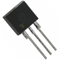


 工商网监
湘ICP备2023018690号
工商网监
湘ICP备2023018690号
